Table of Contents
1-1-1. Product Picture – T611
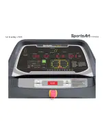
1-2-1. Overlay – T611
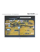
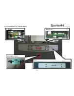
1-3-1. Component Placement – T611 Display Board
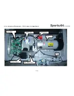
1-3-2. Component Placement – T611 Lower Compartment
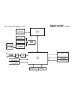
1-4-1. Display Block Diagram – T611
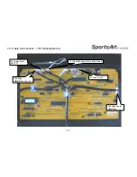
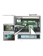
1-5-1. Cable Connections – T611 Display Board
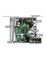
1-5-2. Cable Connections – T611 Drive Board
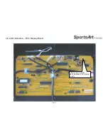
1-6-1. LED Indicators – T611 Display Board
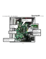
1-6-2. Indicator LEDs – T611 Drive Board
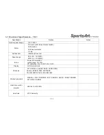
1-7-1. Electronic Specifications – T611
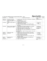
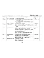
2-1-1. Electronic Malfunction Troubleshooting Table – T611
3-1-1. Troubleshooting – Safety Key Malfunction – T611
3-2-1. Troubleshooting – No Start Up – T611
3-2-2. Troubleshooting – No Start Up – T611
3-3-1. Troubleshooting –Key Malfunction – Soft Keys – T611
3-4-1. Troubleshooting –Key Malfunction – Soft Keys – T611
3-5-1. Troubleshooting – No Incline Operation – T611
3-6-1. Troubleshooting – Incline Position Malfunction – T611
3-7-1. Troubleshooting – HTR Malfunction – T611
3-8-1. Troubleshooting – Fuse Broke at Start –T611
3-8-2. Troubleshooting – Fuse Broke after Motor Moves –T611
3-8-3. Troubleshooting – Fuse Broke after Use – T611
3-9-1. Troubleshooting – ERR-1 Appears before Motor Moves – T611
3-9-2. Troubleshooting – ERR-1 Appears after Motor Moves – T611
3-10-1. Troubleshooting – ERR-3 – T611
3-11-2. Troubleshooting – ERR-7 – T611
3-12-1. Troubleshooting – ERR-10 – T611
3-13-1. Troubleshooting –SERVICE REQUIRED… – T611
3-14-1. Other Topics – Basic Parameter Settings – T611
3-15-1. Other Topics – Error Code Chart – T611
Summary of Contents for T611
Page 1: ...T611 Repair Manual Electronics...
Page 4: ...1 1 Product Picture T611 1 1 1...
Page 5: ...1 2 Overlay T611 1 2 1...
Page 7: ...1 3 Connections T611 Bridge Board 1 3 2 To Safety key board HTR board Soft key Bridge board...
Page 11: ...1 5 Connections T611 Bridge Board 1 5 2 To Safetykey board To HTR board To Display...


