background image

7. Tighten the lower fasteners, then the upper fasteners. Finally push down each

upright post cover until the screw cap fits onto the screw head.

8. Please connect two data cables, as shown in figure A, before you assemble the

display.

9

Fig.7

Fig.8

curved cap

flat cap

Summary of Contents for TR20F

Page 1: ...dmill Assembly Step by Step Instructions 4 Connect To Power 5 TR20F Electronic Display Electronics Display Layout Display Features Programs 6 Guideline For Exercise 7 Adjust The Running Belt 8 Belt Adjustment Procedure 9 Folding And Unfolding The Treadmill 10 Floor Level Adjustment 11 Trouble Shooting Error Messages How to relieve the ERR 7 restriction 12 Main Fuse Failure 13 Wiring Schematic ...

Page 2: ...never be left unattended when plugged in Unplug from outlet when not in use and before putting on or taking off parts 2 Do not operate under blanket or pillow Excessive heating can occur and cause fire electric shock or injury to persons 3 Close supervision is necessary when this treadmill is used near children invalids or disabled persons 4 Use this treadmill only for its intended use as describe...

Page 3: ...rkout clothing Do not wear loose clothing Do not wear shoes with leather soles or high heels Tie back all long hair 18 Straddle the machine with your feet on the right and left staging platform before starting the running belt 19 Work within your recommended exercise level do NOT work to exhaustion 20 If you feel any pain or abnormal STOP YOUR WORKOUT and consult your physician immediately 21 Conn...

Page 4: ...iliarize yourself with this Owner s Manual Whether you are a first time user of a treadmill or a seasoned PRO understanding the correct use of the equipment will enhance your ability to achieve your exercise goals safely and successfully Treadmill profile Display Upper Handle Plastic Left Handle Cap Safety Key Right Handle Cap Left Pedestal Folding Tubing Running Belt Belt Adjustment Bolt Display ...

Page 5: ...ct your dealer immediately To ensure safety to yourself and the treadmill we recommend you drop the sides of the box and slide the treadmill from the box rather than lifting Before assembling your treadmill make sure that you have all following items 1 One safety key 2 One fuse 15A 110v 10A 220v 3 One screwdriver for power connection 4 One hex allen wrench M6 with T handle for pedestal assembly 5 ...

Page 6: ...5 Please see the part illustrations below Left Pedestal Display Handle Right Pedestal ...

Page 7: ...m Thoroughly read the assembly instructions before you begin 1 Tilt up the walk deck as shown until you hear a click sound from knob and make sure the walk deck will not slide down Please also inspect the running belt and confirm that the belt is appropriately located between the two belt alignment guides under the back of treadmill as shown in figure 2 Pull out the knob to slide down the walk dec...

Page 8: ...d the data cable through the right pedestal then insert the right pedestal into the support bracket Also insert the left pedestal into the support bracket on the left side of the treadmill 4 Use an Allen wrench to loosely secure the two pedestals do NOT tighten the screws firmly at this point Fig 3 Fig 4 7 curved washer flat washer ...

Page 9: ...ft and right pedestals Please be carefully the data cable should be fully into the tubing can t be pressed by pedestals 6 Use the Allen wrench M6 to loosely secure the upper fasteners on the pedestals Do NOT tighten firmly Fig 5 Fig 6 8 curved washer flat washer A B ...

Page 10: ...then the upper fasteners Finally push down each upright post cover until the screw cap fits onto the screw head 8 Please connect two data cables as shown in figure A before you assemble the display 9 Fig 7 Fig 8 curved cap flat cap ...

Page 11: ...ully place the display onto the handle Tighten the four screws to secure the display 10 Fig 9 Fig 10 CONNECT TO POWER Connect the power cable as the figure shows and secure it in place by tightening the screws ...

Page 12: ...TR20F ELECTRONIC DISPLAY A Electronics Display Layout 11 Dot Matrix Window Incline Information Scroll Button Workout Information Display Programs Speed Information Keypad Layout ...

Page 13: ...gments HRC 65 Fat Burn Heart Rate Zone HRC 80 Cardio Heart Rate Zone INCLINE Use the INCLINE keys to raise or to lower the treadmill The incline range is from 0 to 15 SPEED The speed range is from 0 5 to 10 MPH or from 0 8 to 16 0 KPH Use the SPEED keys to adjust your desired speed If you are using the HTR feature when the speed is over 4 0 MPH or 6 4 KPH the message FOR ACCURATE HR HOLD SENSORS F...

Page 14: ...5 Custom Interval Custom Course HRC 65 HRC 80 MANUAL Press the Scroll key until your desired program appears in the window STOP PAUSE Hold to Reset 1 In MANUAL mode pressing this key will stop the treadmill When the treadmill is stopped hold this key for three seconds to reset the display and all workout information will be erased 2 In PROGRAM INTV mode if you press this key during your workout in...

Page 15: ...nding LED will blink 2 Choose one program you like and press ENTER to confirm your selection The message PRESS MODE TO SELECT TIME OR DIST will appear Press MODE to set up your desired TIME or DIST Once you begin your workout TIME or DIST will count down 2 1 If you choose TIME a preset value of 10 00 will appear and the TIME LED will light The INCLINE window will show the current incline rate The ...

Page 16: ...5 1 8 3 1 4 6 0 5 1 8 3 1 4 6 Speed KPH 0 8 3 0 5 1 7 6 0 8 3 0 5 1 7 6 Incline 0 0 3 3 6 6 3 3 PRO 4 Speed MPH 0 5 1 8 4 6 3 1 0 5 1 8 4 6 4 6 Speed KPH 0 8 3 0 7 6 5 1 0 8 3 0 7 6 5 1 Incline 0 3 0 3 0 3 0 3 PRO 5 Speed MPH 0 5 3 1 0 5 3 1 0 5 3 1 0 5 3 1 Speed KPH 0 8 5 1 0 8 5 1 0 8 5 1 0 8 5 1 Incline 0 0 3 3 6 6 8 8 1 Once you choose the Custom Interval mode the corresponding LED will be lit...

Page 17: ...Press ENTER to confirm your choice The message ENTER SEGMENT 1 SPEED INCLINE TIME will scroll across the window SEG1 will appear in the information window 2 Press MODE keys to set the SEG1 time press SPEED keys to set the SEG1 speed press INCLINE keys to set the SEG1 incline Press ENTER to confirm all input values 3 After you input the desired SPEED INCLINE and TIME for all eight segments the trea...

Page 18: ...sage window and a preset value of 05 00 will appear on the dot matrix window Press keys to set your desired workout time for this mode Press ENTER to confirm your input 6 Press SPEED keys to set the maximum speed The message window will show MAX and the motor will start running If no heart rate signal is detected at this time you will not be able to start the treadmill Before entering the HRC prog...

Page 19: ...0 minutes to realize an aerobic benefit Beginners should always start slowly and bring their workout sessions up to 20 minutes or more As your fitness level increases you will be able to maintain your heart rate in the training zone for longer periods Usually between 20 and 30 minutes When first starting your workout use the first several minutes to warm up then slowly increase your workload to br...

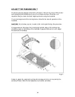
Page 20: ...running belt is critical for the smooth operation of the treadmill Do not allow any one to walk on the running belt during this procedure The gap between the edge of the running belt and the edge of the landing strip should be equal on both sides of the treadmill If gap A and B are not even adjust the walk belt immediately Failure to adjust the walk belt could result in damage which is not covered...

Page 21: ...belt is too far left Turn the left belt adjustment bolt located at the rear of the treadmill clockwise 1 4 turn at a time using the Allen wrench Then turn the right belt adjustment bolt counterclockwise 1 4 turn Let the treadmill run 30 seconds then check the position of the belt If the belt still has not returned to the proper zone repeat with another 1 4 turn on both sides until the belt has ret...

Page 22: ...ler bolts clockwise 1 4 turn at a time see Fig 12 1 Then check the belt tension again if more adjusting is required give both adjusting bolts another slight turn Do not adjust over 2 full turns Conversely if there is not enough give adjust both rear roller bolts counterclockwise 1 2 turn at a time To avoid injury special care must be taken when adjusting the running belt Remove any loose clothing ...

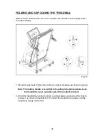
Page 23: ...turning it clockwise as shown in figure A 2 Unfold the treadmill by turning the knob counterclockwise and pull out the knob to release it as shown in figures B C Put down the treadmill very slowly until the treadmill is steady on the floor Note The locking feature is essential to the safety of people and pets Lock the treadmill to avoid operation when the treadmill is folded Fig 13 ...

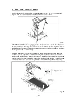
Page 24: ... them in the same direction and with the same number of turns so that they will touch the floor evenly Similarly when applying pressure to sides A and B if transport wheel B does not touch the ground adjust levelers b1 and b2 by turning them in the same direction and with the same number of turns so that they will touch the floor evenly Adjust the levelers until the treadmill is steady and firmly ...

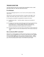
Page 25: ...ecurely or contact your dealer for further information This detection only takes place when the power switch is turned on E 14 The motor temperature is too high Please switch off the treadmill and allow the treadmill to rest for one hour to cool down the motor Then resume normal use again When the E 7 message appears the DC motor will not operate Try the following method to start the treadmill Rem...

Page 26: ... 120 volts or 7amp 220 240 volts To remove the main fuse push the fuse cap toward the machine and turn it counterclockwise then pull out the fuse cap Remove the fuse from the cap Insert a new fuse of the appropriate type into the fuse cap and insert it into the machine Turn the fuse cap clockwise to secure the fuse in place See Fig A B C If the unit does not work after changing the fuse please con...

Page 27: ...Wiring Schematic 26 Your Authorized Distributor TR20F ...

Reviews: