background image

D. Safety Key:

The safety key feature is required to be in place for the treadmill to operate. This
safety device is intented to provide the user a safe mechanism to stop the
treadmill should a user stumble and fall.

The electonics will prompt with the message - SAFETY KEY, to remind the user to
replace the safety key in its proper place.

15

Summary of Contents for TR21F

Page 1: ...21F Electronic Display Electronics Display Layout Display Features Display Controls Safety Key 6 How To Use Your TR21F Treadmill Quick Start and Touch N Go QuickStart Programs User Selection Workout S...

Page 2: ...ever be left unattended when plugged in Unplug from outlet when not in use and before putting on or taking off parts 2 Do not operate under blanket or pillow Excessive heating can occur and cause fire...

Page 3: ...kout clothing Do not wear loose clothing Do not wear shoes with leather soles or high heels Tie back all long hair 18 Straddle the machine with your feet on the right and left staging platform before...

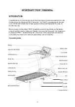
Page 4: ...ing one of the finest piece of exercise equipment on the market today the SportsArt TR21F treadmill The TR21F is designed with the end user in mind and constructed of high quality materials and design...

Page 5: ...t your dealer immediately To ensure safety to yourself and the treadmill we recommend you drop the sides of the box and slide the treadmill from the box rather than lifting Before assembling your trea...

Page 6: ......

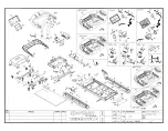
Page 7: ...t Rotator Cover 1 TR21 100 29 Fuse Holder 1 FSHR 01 101 Pivot Hardware 2 TR21 86 30 On Off Switch 1 ONSW 01 102 Front Roller 1 TR21 102 31 Cable Filter to Drive Board 1 6300 70 103 Walk Belt 1 TR21 10...

Page 8: ...5 Please see the part illustrations below Left Pedestal Display Handle Right Pedestal...

Page 9: ...am Thoroughly read the assembly instructions before you begin 1 Tilt up the walk deck as shown until you hear a click sound from knob and make sure the walk deck will not slide down Please also inspec...

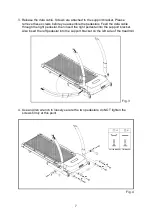
Page 10: ...the data cable through the right pedestal then insert the right pedestal into the support bracket Also insert the left pedestal into the support bracket on the left side of the treadmill 4 Use an All...

Page 11: ...ta cable insert the handle onto both the left and right pedestals Please be carefully the data cable should be fully into the tubing can t be pressed by pedestals 6 Use the Allen wrench M6 to loosely...

Page 12: ...hen the upper fasteners Finally push down each upright post cover until the screw cap fits onto the screw head 8 Please connect two data cables as shown in figure A before you assemble the display 9 F...

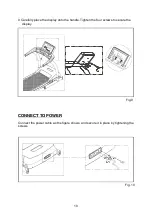
Page 13: ...lly place the display onto the handle Tighten the four screws to secure the display 10 Fig 9 Fig 10 CONNECT TO POWER Connect the power cable as the figure shows and secure it in place by tightening th...

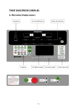
Page 14: ...TR21F ELECTRONIC DISPLAY A Electronics Display Layout 11 Current HR Window Information Window ActivZone Dot Matrix Display Numeric Keypad Programs To Start Instruction...

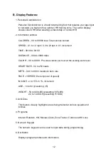
Page 15: ...iles CAL HR 0 0 to 999 9 Provides calorie per hour at the existing work level HEART RATE 30 to 250 beats METS 0 00 to 99 00 metabolic burn rate PACE 1 SPEED the reciprocal of speed INCLINE o to 15 in...

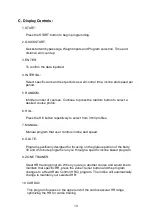
Page 16: ...titively to select from 3 Hill profiles 7 MANUAL Manual program that user controls incline and speed 8 GLUTE Program specifically designed for focusing on the gluteus portion of the body 30 and 45 min...

Page 17: ...utton also functions as quickstart The speed range is from 1 mph to 12 mph 0 2 kph to 20 kph 16 STOP HOLD TO RESET a Pressing the stop button once will stop the treadmill and place the electronics in...

Page 18: ...he treadmill to operate This safety device is intented to provide the user a safe mechanism to stop the treadmill should a user stumble and fall The electonics will prompt with the message SAFETY KEY...

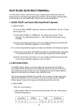
Page 19: ...rt a program The treadmill will start at 1 mph after which the speed can be modified 2 At any time during your workout you can change programs by pressing the Touch N Go QuickStart programs or Zone Tr...

Page 20: ...the correct user and hold the CHANGE button To modify follow the same process as above To remove a personalized user name press and hold the CLEAR button for 3 seconds This will revert the USER ID to...

Page 21: ...D COOL DOWN Program Upon completing the program the electronics will display accumulative data for your workout Following the treadmill will automatically go to a COOL DOWN program Speed will gently l...

Page 22: ...and speed one by one Press ENTER to confirm your input 2 Enter WORK time Display shows SET WORK xx 00 time is set in increments of 1 minute Press INCLINE or numeric keypad to set up WORK time incline...

Page 23: ...the display When you complete your workout goal you will directly go into a COOL DOWN program User parameters determine basic operating features To change these parameters please follow up the instruc...

Page 24: ...minutes to realize an aerobic benefit Beginners should always start slowly and bring their workout sessions up to 20 minutes or more As your fitness level increases you will be able to maintain your...

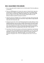
Page 25: ...unning belt is critical for the smooth operation of the treadmill Do not allow any one to walk on the running belt during this procedure The gap between the edge of the running belt and the edge of th...

Page 26: ...elt is too far left Turn the left belt adjustment bolt located at the rear of the treadmill clockwise 1 4 turn at a time using the Allen wrench Then turn the right belt adjustment bolt counterclockwis...

Page 27: ...oller bolts clockwise 1 4 turn at a time see Fig 12 1 Then check the belt tension again if more adjusting is required give both adjusting bolts another slight turn Do not adjust over 2 full turns Conv...

Page 28: ...urning it clockwise as shown in figure A 2 Unfold the treadmill by turning the knob counterclockwise and pull out the knob to release it as shown in figures B C Put down the treadmill very slowly unti...

Page 29: ...them in the same direction and with the same number of turns so that they will touch the floor evenly Similarly when applying pressure to sides A and B if transport wheel B does not touch the ground a...

Page 30: ...the motor is overheated Turn off unit and wait one hour before using it again Or stop working out on the unit Wait until the message RESET POWER SWITCH appears then turn the unit off and on before usi...

Page 31: ...20 volts or 10amp 220 240 volts To remove the main fuse push the fuse cap toward the machine and turn it counterclockwise then pull out the fuse cap Remove the fuse from the cap Insert a new fuse of t...

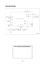
Page 32: ...Wiring Schematic 29 Your Authorized Distributor TR21F...

Reviews: