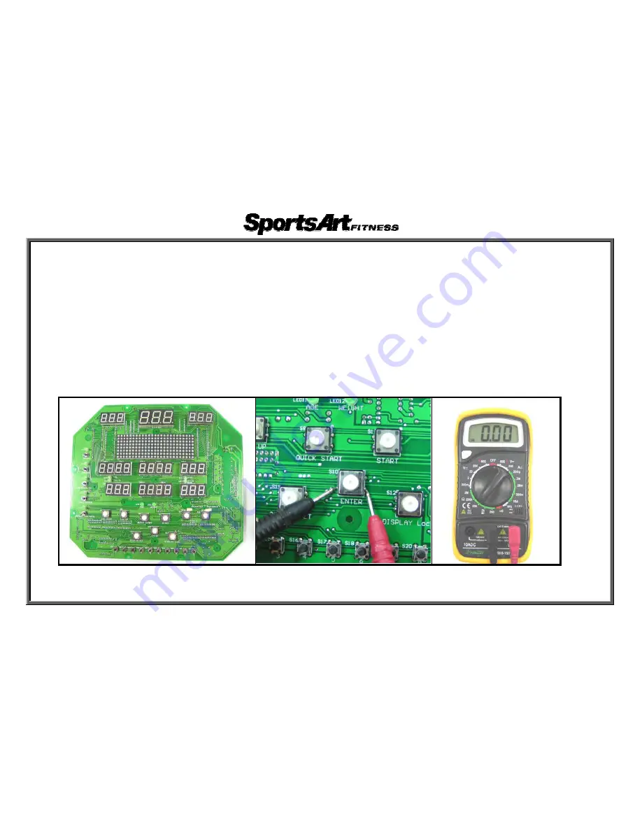
XT20 Display Board Key Test
1. Test Procedure
1-1. Test for continuity
(1) Put voltmeter to the ohm setting. Place probes on the two terminals on the right or left side as shown.
(2) Press on the key. Voltmeter should show 0
Ω
.
(3) If the display shows no reaction, the key is broken.
1-2. Test for open
(1) Put voltmeter to the ohm setting. Place probes on the two terminals on the right or left side as shown.
(2) Without pressing on a key, there should be no reaction on the voltmeter.
(3) If the voltmeter reads 0 ohm when the key is not pressed, the key has a short. Replace it.
Left Picture Right Picture
7-10-1
Summary of Contents for XT20 Cross Trainer
Page 1: ...XT20 Cross Trainer Repair Manual SPORTSART INDUSTRIAL CO LTD...
Page 5: ...XT20 Picture 1 1 1...
Page 6: ...XT20 Display 1 2 1...
Page 8: ...XT20 Lower Body Front 1 3 2 AC alternator Flywheel Electro magnet Battery Reed switch...
Page 9: ...XT20 Display 1 4 1...
Page 10: ...XT20 Display Board Front 1 5 1...
Page 11: ...XT20 Display Board Back 1 5 2...
Page 31: ...XT20 Display Board Component Placement 5 1 2...
Page 35: ...XT20 Drive Board Component Placement 5 2 2...
Page 53: ...XT20 Alternator Test 1 Alternator test configuration 7 1 1...
Page 59: ...XT20 Alternator Power Test at the Drive Board 1 Test Configuration 7 5 1...
Page 61: ...XT20 Battery Test at the Drive Board 1 Test Configuration 7 6 1...
Page 64: ...Test Configuration LEG Resistance Voltage Test 7 7 2...
Page 66: ...XT20 VCC Voltage Test at the Drive Board 1 Test Configuration Normal reading 5 VDC 7 8 1...
Page 68: ...XT20 VCC Voltage Test at the Display Board 1 Test Configuration 7 9 1 Capacitor C10...


