36
37
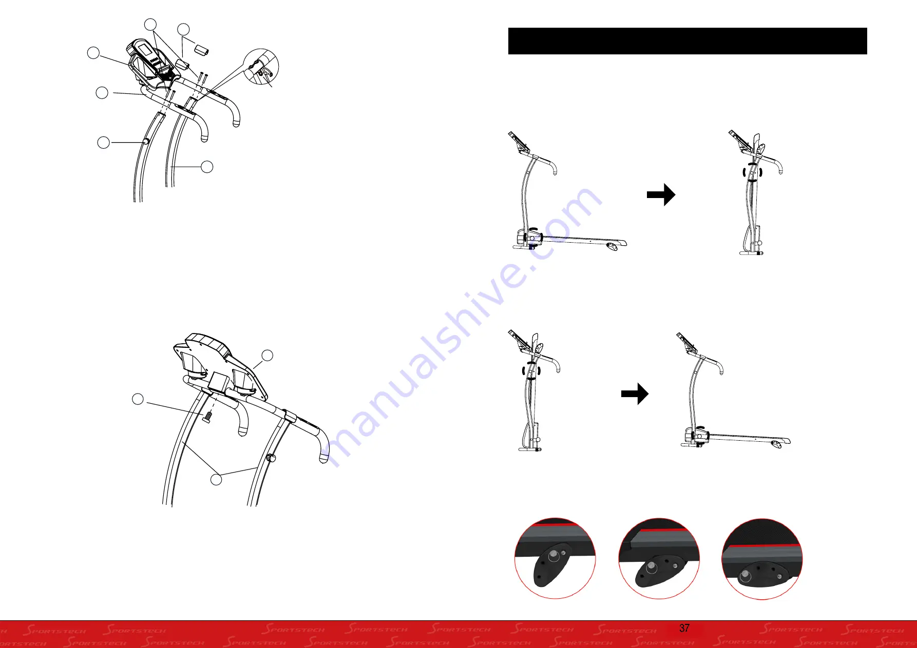
Step 2:
A.Remove the four Head Hex Socket Screws (17) in the end of the Left Stand Tube and Right Stand
Tube. B.Attach the Handlebar (70) onto both ends of the Stand Tube, tighten the screws with the
Allen Key provided.
C. Connect the wire that comes from the Computer Console (5) to the Main Control Cable Socket
from the right handlebar support of the Right Stand Tube .
D.Install both Handlebar Covers (19) onto the Handlebar (70).
Step 3:
A.Turn the Computer Console (5) up or down to align the Socket Head Screw hole.
B. Lock the Computer Console (5) in place by tightening the Socket Head Screw (9).
19
70
84
20
5
17
Haupt-Steuerkabel Steckverbindung
54
9
5
Main Control Cable Socket
TO FOLD:
After use, unscrew the safety lock on the bottom frame, fold the treadmill and pull the expandable
safety lock out from the left Upright and release to lock the treadmill in an upright position.
To avoid losing the safety lock, screw the safety lock to the bottom and upper frames whilst in an
upright position.
TO UNFOLD:
Unscrew the safety lock on the bottom frame, release the expandable safety lock and lower the
bottom frame to the ground. Screw the safety lock to the bottom frame to lock the upper frame in an
upright position.
FOLDING INSTRUCTIONS
MANUAL SLOPE FUNCTION:
To change the gradient angle you have to pull the safety pin and push it back in one of three
possible positions. This allows a maximum angle of 18° at step 3.
Step 1 Step 2 Step 3
37
Summary of Contents for F15
Page 1: ...F15 DE EN ES FR IT ...


