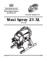
background image


ProSpray 3.20 

GB

Safety precautions 

1. 

Safety regulations for Airless spraying

1.1 

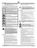
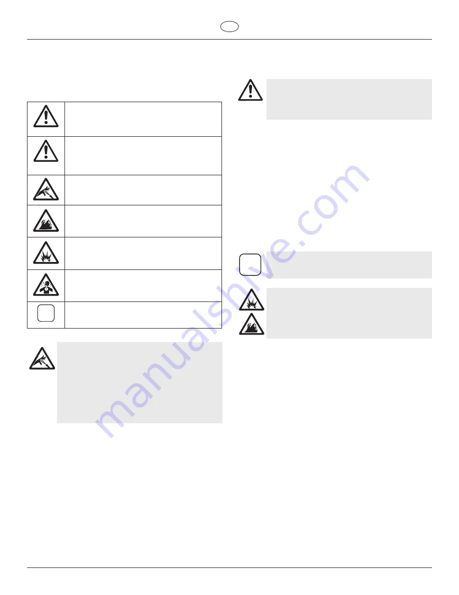
Explanation of symbols used

This manual contains information that must be read and understood 

before using the equipment. When you come to an area that has one 

of the following symbols, pay particular attention and make certain 

to heed the safeguard.

This symbol indicates a potential hazard that 

may cause serious injury or loss of life. Important 

safety information will follow.

Attention

This symbol indicates a potential hazard to you 

or to the equipment.  Important information that 

tells how to prevent damage to the equipment or 

how to avoid causes of minor injuries will follow.

Danger of skin injection

Danger of fire from solvent and paint fumes

Danger of explosion from solvent, paint fumes 

and incompatible materials

Danger of injury from inhalation of harmful 

vapors

i

Notes give important information which should 

be given special attention.

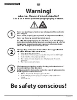
HAZARD:  INjECTION INjuRy

Attention: Danger of injury by injection! A high 

pressure stream produced by this equipment can 

pierce the skin and underlying tissues, leading to 

serious injury and possible amputation.
Do not treat a spraying injury as a harmless cut. In 

case of injury to the skin through coating materials 

or solvents, consult a doctor immediately for quick 

and expert treatment. Inform the doctor about the 

coating material or solvent used.

PREVENTION:
 

•  NEVER aim the gun at any part of the body. 


•  NEVER allow any part of the body to touch the fluid stream. 

DO NOT allow body to touch a leak in the fluid hose.


•  NEVER put your hand in front of the gun.  Gloves will not 

provide protection against an injection injury.


•  ALWAYS lock the gun trigger, shut the fluid pump off and 

release all pressure before servicing, cleaning the tip guard, 

changing tips, or leaving unattended. Pressure will not be 

released by turning off the engine. The PRIME/SPRAY valve 

or pressure bleed valve must be turned to their appropriate 

positions to relieve system pressure.


•  ALWAYS keep tip guard in place while spraying. The tip guard 

provides some protection but is mainly a warning device.


•  ALWAYS remove the spray tip before flushing or cleaning the 

system.


•  NEVER use a spray gun without a working trigger lock and 

trigger guard in place.


•  All accessories must be rated at or above the maximum 

operating pressure range of the sprayer.  This includes spray 

tips, guns, extensions, and hose.

HAZARD:  HIGH PRESSuRE HOSE

The paint hose can develop leaks from wear, kinking 

and abuse.  A leak can inject material into the skin.  

Inspect the hose before each use.

PREVENTION:
 

•  High-pressure hoses must be checked thoroughly before they 

are used.


•  Replace any damaged high-pressure hose immediately.


•  Never repair defective high-pressure hoses yourself!


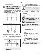
•  Avoid sharp bends and folds: the smallest bending radius is 

about 20 cm.


•  Do not drive over the high-pressure hose. Protect against 

sharp objects and edges.


•  Never pull on the high-pressure hose to move the device.


•  Do not twist the high-pressure hose.


•  Do not put the high-pressure hose into solvents. Use only a 

wet cloth to wipe down the outside of the hose.


•  Lay the high-pressure hose in such a way as to ensure that it 

cannot be tripped over.

i

Only use Spray Centre original-high-pressure 

hoses in order to ensure functionality, safety and 

durability.

HAZARD:  EXPLOSION OR FIRE

Solvent and paint fumes can explode or ignite.  

Severe injury and/or property damage can occur.

PREVENTION:
 

•  Do not use materials with a flashpoint below 38° C (100° F). 

Flashpoint is the temperature at which a fluid can produce 

enough vapors to ignite.


•  Do not use the unit in work places which are covered by the 

explosion protection regulations.


•  Provide extensive exhaust and fresh air introduction to 

keep the air within the spray area free from accumulation of 

flammable vapors.


•  Avoid all ignition sources such as static electricity sparks, 

electrical appliances, flames, pilot lights, hot objects, and 

sparks from connecting and disconnecting power cords or 

working light switches.


•  Do not smoke in spray area.


•  Place sprayer sufficient distance from the spray object in a 

well ventilated area (add more hose if necessary).  Flammable 

vapors are often heavier than air.  Floor area must be 

extremely well ventilated.  The pump contains arcing parts 

that emit sparks and can ignite vapors. 


•  The equipment and objects in and around the spray area must 

be properly grounded to prevent static sparks.


•   Use only conductive or earthed high pressure fluid hose.  Gun 

must be earthed through hose connections.


•   Power cord must be connected to a grounded circuit (electric 

units only).


•  Always flush unit into separate metal container, at low pump 

pressure, with spray tip removed.  Hold gun firmly against side 

of container to ground container and prevent static sparks.

Summary of Contents for Maxi Spray 21.XL

Page 1: ...Edition 9 2015 0532 838A GB Operating manual Airless high pressure spraying unit Exclusive Suppliers of PS 3 20 Maxi Spray 21 XL...

Page 2: ...ing material or solvent used The operating instructions state that the following points must always be observed before starting up 1 Faulty units must not be used 2 Secure Spray Centre spray gun using...

Page 3: ...ction filter 9 8 3 Cleaning the high pressure filter 9 8 4 Cleaning Airless spray gun 10 Page 9 Remedy in case of faults 10 10 Servicing 11 10 1 General servicing 11 10 2 High pressure hose 11 11 Repa...

Page 4: ...be rated at or above the maximum operating pressure range of the sprayer This includes spray tips guns extensions and hose HAZARD High Pressure Hose The paint hose can develop leaks from wear kinking...

Page 5: ...follow the material manufacturer s instructions for safe handling of paint and solvents Clean up all material and solvent spills immediately to prevent slip hazard Wear ear protection This unit can pr...

Page 6: ...e unit meticulously with the appropriate cleaning materials Coating materials with sharp edged additional materials These have a strong wear and tear effect on valves high pressure hose spray gun and...

Page 7: ...ose 5 Frame 6 Drip cup 7 Power cord 8 ON OFF switch 9 Relief valve Lever position vertical PRIME k circulation Lever position horizontal SPRAY p 10 Pressure control knob 11 Oil cup for EasyGlide EasyG...

Page 8: ...m Fig 3 item 1 to make sure the inlet ball is free 6 ProSpray 3 20 GB Description of unit Starting operation 3 5 Technical data Voltage 220 240 VAC 50 60 Hz or 100 120 VAC 50 60 Hz Max current consump...

Page 9: ...ion 4 2 Connection to the mains network Attention The unit must be connected to an appropriately grounded safety outlet Before connecting the unit to the mains supply ensure that the line voltage matc...

Page 10: ...see Page 18 Section 12 2 If a non standard tip is installed proceed according to the relevant operating manual 7 Depending on the model leave the suction tube or the suction hose and return hose immer...

Page 11: ...til the unit is empty 12 Switch the unit OFF 8 1 Cleaning unit from outside First of all pull out mains plug from socket Attention Danger of short circult through penetrating water Never spray down th...

Page 12: ...Refill the coating material 3 Clean or replace the filter 4 Clean connecting points Replace O rings if necessary Secure suction hose with retaining clip 1 Replace 2 Replace tip 3 Turn pressure control...

Page 13: ...unit OFF Before all repair work Unplug the power plug from the outlet 11 1 Relief valve Attention The valve housing 4 should not be repaired If worn it should always be replaced with a new one 1 Use a...

Page 14: ...12 13 11 3 Packings Disassembly Fig 12 1 Remove inlet valve housing in accordance with the steps in Chapter 11 2 It is not necessary to remove the outlet valve 2 Remove the yoke screw 14 and washer 15...

Page 15: ...es in the yoke where the dowel 16 is inserted 9 Install the dowel pin 16 to connect the yoke 17 to the piston 18 The piston may have to be moved up or down to do this 10 Install the yoke screw 14 and...

Page 16: ...lide the motor cover 2 over the motor Secure the motor cover with the four motor cover screws 1 1 3 2 8 5 9 6 4 7 11 5 Replacing the Gears i The following procedure must only be performed by a Wagner...

Page 17: ...7 1 3 6 8 10 9 7 2 5 4 11 7 Resetting the Pressure Switch Timing i The following procedure must only be performed by a Wagner Authorized Service Center i The components of the pressure switch must be...

Page 18: ...ng in the pump housing pull gently on the wires until the connector is shown through the opening 5 Disconnect the black wire that connects the circuit board to the circuit breaker 6 6 Disconnect the w...

Page 19: ...the relief valve handle fully counterclockwise k Circulation 2 Switch off the gasoline engine 3 Dismount the tip from the spray gun 4 Place tip in an appropriate cleaning agent until all coating mater...

Page 20: ...red red red red red 0553113 0553213 0553313 0553413 0553513 0553613 0553813 Fillers Rust protection paints 115 215 315 415 515 615 715 815 10 20 30 40 50 60 70 80 0 015 0 38 0 015 0 38 0 015 0 38 0 01...

Page 21: ...hite white white white white white white white white white white white white white white white white white white white white white white white white white white white white white white white white whi...

Page 22: ...225 629 Order no 0271 064 D7 Nozzles 113 417 Order no 0271 063 L10 Nozzles 208 510 Order no 0271 042 D10 Nozzles 111 419 Order no 0271 045 S10 Nozzles 527 235 Order no 0271 049 Medium L20 Nozzles 210...

Page 23: ...4 mm MW fine 0043 235 Nozzle extension complete 15 cm F thread 0556 051 TradeTip 3 FineFinish nozzle 308 0554 308 TradeTip 3 FineFinish nozzle 410 0554 410 TradeTip 3 FineFinish nozzle 412 0554 412 Tr...

Page 24: ...1 4 10m Spraypack consisting of basic unit 2311659 Airless gun AG 14 NPS 1 4 incl Trade Tip 2 nozzle holder F thread and Trade Tip 2 Fine Finish 410 2311660 2311853 TempSpray H 226 ideal for dispersi...

Page 25: ...alia 34 20060 Gessate MI Italia Tel 39 02 9592920 1 Telefax 39 02 95780187 info wagnercolora com CH Wagner International AG Industriestrasse 22 9450 Altst tten Schweiz Tel 41 71 7 57 22 11 Telefax 41...

Page 26: ...24 ProSpray 3 20 Accessories illustration 3 1 5 7 9 10 2 4 6 8...

Page 27: ...0 Metex Reuse Reuse for pre filtering of coating material in vessel Place suction pipe in the reuse 0034 952 Sieve package 5 pcs for paint 0034 951 Sieve package 5 pcs for dispersion 7 0034 383 Gun fi...

Page 28: ...assembly See separate listing Suction system for stand 1 2 3 4 5 6 9 7 8 Pos PS 3 20 Description 1 0551706 Siphon tube assembly includes items 1 and 3 6 2 0558659A Return tube 3 0279459 Clip 4 029556...

Page 29: ...7 0532234A EMI filter 8 9800341 Screw 4 9 9800340 Ground screw 2 10 0512213 2nd stage gear assembly 11 0519001 Main housing assembly Pos PS 3 20 Description 12 0507745 Gasket 13 0507254 PRIME SPRAY va...

Page 30: ...14 9832128 Dowel pin 15 0293395 Screw 16 0296289 Seal 17 0532357 Plug 18 0532254A Piston assembly includes items 18 23 19 0551262 Upper cage 20 0551263 Washer 21 50164 Outlet valve ball 22 0551620 Ou...

Page 31: ...7 10 11 5 6 11 1 2 4 9 8 11 4 11 3 Pos PS 3 20 Description 1 0532238A Leg right 2 0532356 Cord wrap 3 0508660 Screw 4 805 342 Foot 2 5 0532239A Leg left 6 0509856 Nut 7 9805230 Screw 8 806 216 Clip 9...

Page 32: ...roduct has to be sent without charge or presented together with the original purchase document that includes details of the purchase date and the name of the product In order to claim for an extension...

Reviews: