AA
09
0AG
Seri
es
Air
Mo
tor
‐
Driven
Tank
Wa
sher
0
8/
15/
20
11
11
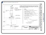
DISASSEMBLY OF THE UNIT (SEE PARTS LIST PL 090AG)(REPAIR KIT #AB090-KIT)
1. If it has not already been done, the air motor sub-assembly should be removed as described in the removal
of #46340 air motor drive section above.
2. Next, tap out the groove pin (5) and inspect hole in shaft (6). Remove any burrs and sharp edges.
3. Unscrew the upper shaft seal body sub-assembly (3) and slide off the shaft (6).
4. Inspect the o-ring and bushing inside the upper shaft seal body sub-assembly (3). If damaged or worn,
replace with new sub-assemblies.
5. Using a 15/16” using a 15/16” open-end wrench across the flats of the gear (12), loosen the entire assembly
from the extension tube (7). Be careful not to damage gear teeth.
6. Remove shaft (6) by loosening shaft nut (8) and unscrewing the shaft (6) from the yoke (13). These are left
hand threads.
7. Do not move shaft nut (8) more than necessary as this serves as an indicator during reassembly.
8. When shaft (6) is removed, loosen yoke nut (9) by holding collar (10). Remove yoke nut (9) and collar (10).
This will allow replacement of thrust washer (11).
9. Replace collar (10) until it contacts thrust washer (11). Do not over-tighten.
10. Hold collar (10) and tighten yoke nut (9) against collar (10) torque to 20 ft/lbs. Thread shaft (6) back into
yoke (13) until shaft nut (8) contacts top of yoke (13).
REASSEMBLY OF THE UNIT (SEE PARTS LIST PL 090AG)
1. Tighten the shaft (6) against yoke (13). Remember these are left hand threads.
2. Apply lubricant oil* to the end of the shaft (6) and insert into the extension tube (7).
3. Align shaft (6) and start it into upper bushing retainer sub-assembly (3).
4. Thread gear (12) into extension tube (7). This will push assembly through upper bushing retainer sub-
assembly (3). Tighten gear (12) into extension tube (7) to 20 ft/lbs.
5. Replace groove pin (5) and air motor assembly (1). Refer to the previous section titled replacement of
#46340 air motor drive.
6. Be sure to align slot in air motor assembly with groove pin (5). If groove pin (5) is not contacting slot or motor
cannot be seated properly due to interference, then the shaft is either threaded into the yoke (13) too far or
not enough. This is why, during disassembly, care should be taken when loosening the shaft nut (8).
USE APPROPRIATE LUBRICANT IF UNIT IS USED IN FOOD OR PHARMACEUTICAL APPLICATIONS.
REPLACEMENT OF #46340 AIR MOTOR DRIVE (SEE PARTS LIST DRAWING PL 46340)
1. If it is not already attached, align the keyway on the coupling (5) with the key (6) on the gear motor sub-
assembly (11) shaft and lightly tap the coupling (5) until it bottoms on the shaft.
2. Insert the coupling (5) through the hole in the top of the 190 inlet casting.
3. The slot on the coupling (5) should be aligned and indexed over the groove pin and drive shaft on the 190
assembly.
4. The air motor drive assembly can now be rotated until the through holes on the inlet casting align with the m5
female threaded inlet holes on the air motor drive assembly.
5.
Using a 4 mm hex Allen Wrench, secure the gear motor sub-assembly (11) to the inlet casting using two m5
bolts (1) and spring lock washers(2).
Before re-installing in a tank, connect an air line to the air motor
drive to make sure the unit works properly.


