background image


AA

09

0AG


Seri

es


Air


Mo

tor

Driven


Tank


Wa

sher


0

8/

15/

20

11


7

SAFETY


PRECAUTIONS


YOUR


SAFETY


AND


THE


SAFETY


OF


OTHERS


IS


EXTREMELY


IMPORTANT.


WE HAVE PROVIDED IMPORTANT SAFETY MESSAGES IN THIS MANUAL FOR YOUR 
PRODUCT. ALWAYS READ AND OBEY ALL SAFETY MESSAGES. 
 

THIS IS THE SAFETY ALERT SYMBOL. THIS SYMBOL ALERTS YOU TO HAZARDS 
THAT CAN KILL OR HARM YOU AS WELL AS OTHERS. THE SAFETY ALERT 
SYMBOL AND THE WORDS “DANGER” AND “WARNING” WILL PRECEDE ALL 
SAFETY MESSAGES. READ THE FOLLOWING WORDS AND WHAT THEY SIGNIFY: 


DANGER 


YOU MAY BE KILLED OR SERIOUSLY INJURED IF YOU DON’T FOLLOW THESE 
INSTRUCTIONS. 


WARNING 


YOU MAY BE SERIOUSLY INJURED IF YOU DON’T FOLLOW THESE INSTRUCTIONS. 
 
ALL SAFETY MESSAGES WILL IDENTIFY THE HAZARD, TELL YOU HOW TO REDUCE THE 
CHANCE OF INJURY AND TELL YOU WHAT CAN HAPPEN IF THE SAFETY INSTRUCTIONS 
ARE NOT FOLLOWED. 


INSTALLATION


Qualified personnel must perform all work required to assemble, install, operate, maintain and 
repair this equipment. Improper installation and operation can result in severe personal injury 
and/or damage to property. Correct installation is your responsibility. 

WARNING 

Install proper guards as needed. Follow basic lifting guides when transporting or handling this 
product. Failure to follow this instruction can result in back injury, burns or other serious injury. 


CONNECTIONS 

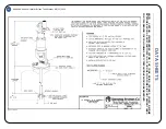
Please refer to datasheet 090AG during installation. Connect the air muffler (shipped loose) to the 
air motor exhaust connection. The exhaust connection is the threaded connection on the left as 
you face the motor openings. Connect the lubricator sub-assembly to the air inlet connection of the 
air motor. The inlet connection is the threaded connection on the right as you face the motor 
openings. Attach a compressed air line to the quick connect fitting of the pressure regulator and 
verify that the nozzle hub rotates clockwise when viewed from the nozzle hub end by applying air 
pressure to the motor. Connect the liquid line to the inlet connection of the liquid inlet body. 
 

MOUNTING 

Bolt or clamp the unit to the tank to be cleaned as dictated by the mounting flange provided.  
Adjustable flanges allow easy positioning of the tank wash unit to various spray depths for 
maximum cleaning effectiveness.


Summary of Contents for AA090AG Series

Page 1: ...OWNER S MANUAL MI AA090AG AA090AG SERIES AIR MOTOR DRIVEN TANK WASHER Spraying Systems Co Experts in Spray Technology a...

Page 2: ...onnection 8 Mechanical clearances 8 Grounding 8 High impact sprays 8 Air motor lubrication 9 Automatic lurication 9 OPERATION 9 MAINTENANCE Removal Replacement of spray nozzles 10 Removal Replacement...

Page 3: ...Washer is designed for high pressure 500 psi 35 bar MAX washing of tanks up to a recommended maximum diameter of 8 feet 2 4 m with heated 200 F 93 C MAX or unheated solutions at flow rates up to 7 3...

Page 4: ...AIR SUPPLY LINE LIQUID INLET CONN 1 NPT r or 1 BSPT r CAN BE PERMANENTLY INSTALLED OR USED AS A PORTABLE UNIT MULTI AXIS ROTATION PROVIDES FULL COVERAGE or INTERNAL TANK SURFACES MOTORIZED DRIVE IS M...

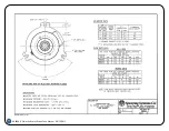
Page 5: ...8 2 3 1 1 5 4 0 ASSUMING EXHAUST FILTER IS CLEAN 31 REVOLUTIONS ARE REQUIRED FOR 1 COMPLETE CYCLE FLOW RATE DATA U S UNITS AVG TOTAL FLOW OF 2 NOZZLES EQUAL CAPACITY GALLONS PER MINUTE NOZZLE INLET P...

Page 6: ...2 6 0 8 2 AIR INLET CONN 1 4 NPT M GEAR REDUCER PERMANENTLY LUBRICATED APPROX TIME FOR ONE COMPLETE CYCLE IN MINUTES 090 190 10 11 5 5 6 0 4 0 5 0 PARTS LIST PL46340 APPROX WEIGHT 6 25 lbs 2 8 kg REVO...

Page 7: ...vere personal injury and or damage to property Correct installation is your responsibility WARNING Install proper guards as needed Follow basic lifting guides when transporting or handling this produc...

Page 8: ...earth ground via an approved grounding method Likewise a ground wire should be affixed to the tank and terminated at an earth ground DANGER It is not sufficient to ground only the tank washer or the...

Page 9: ...oper operations do not run the unit dry always keep liquid flow on before stopping the air motor WARNING Do not use combustible gases to drive the air motor Sound level from motor may exceed 85db A Ch...

Page 10: ...nd clean and inspect yoke 13 seating surfaces 5 Install new pinion bushings 16 until they seat fully against the yoke 13 6 Clean and inspect the pinion shaft 18 and slide through the pinion bushings 1...

Page 11: ...he end of the shaft 6 and insert into the extension tube 7 3 Align shaft 6 and start it into upper bushing retainer sub assembly 3 4 Thread gear 12 into extension tube 7 This will push assembly throug...

Page 12: ...FIiied TEFLON 2 Req d 17 CP38836 303SS Woodruff Key Type 303 Stainless Staal 18 CP38840 316SS Pinion Shaft Type 316 Stainless Steel 19 w Nozzle Type 416 Hardened Stainless Steel 2 Raq d 20 CP38838 31...

Page 13: ...pler Brass 2 CP22024 I Coupler Nipple Steel 3 CP22025 Filter Regulator 4 26383 1 4 30 Pressure Gauge 5 CP7998 7 8 Close Nipple Brass 6 CP22027 Lubricator No 21030 Lubricator Assembly DESCRIPTION PARTS...

Page 14: ...l 10 CP46346 4 IBO Metric Set Screw Cup Point M4 x 7 x 4 mm LG Alloy Steel Black Oxide Coating 11 46351 Gear Motor Sub Assembly Consists Of The Following Items 6 7 8 9 10 12 46350 Air Motor Gast 1UP N...

Page 15: ...ty and fitness for a particular purpose Because of the difficulty of ascertaining and measuring damages hereunder it is agreed that except for claims for bodily injury Seller s liability to the Buyer...

Page 16: ...Road P O Box 7900 Wheaton IL 60187 7901 Tel 1 800 95 SPRAY Intl Tel 1 630 665 5000 Fax 1 888 95 SPRAY Intl Fax 1 630 260 0842 Visit our Website at http www spray com Spray Nozzles Spraying Systems Co...

Reviews: