AA
19
0D
AG
Se
ries
Air
Motor
‐
Driven
Tank
Washer
|
1
1/
1
1/
20
10
|
RE
V
.
1
14
MAINTENANCE
IT IS YOUR RESPONSIBILITY TO REGULARLY INSPECT AND MAKE NECESSARY REPAIRS
TO THIS PRODUCT IN ORDER TO MAINTAIN PROPER OPERATION.
IT IS RECOMMENDED
THAT THE BUSHINGS AND SEALS BE INSPECTED EVERY 1000 HOURS OF OPERATION OR
SOONER IF EXCESSIVE LEAKAGE OF THE SEALS OCCURS.
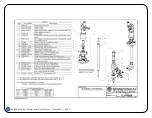
REMOVAL AND REPLACEMENT OF SPRAY NOZZLES (ITEM 17 ON PARTS LIST DRAWING PL 190DAG &
PL 190DAGH)
Make sure the unit is completely disconnected from the
air source before attempting to service nozzles.
1. Unscrew spray nozzles (17) from nozzle hub (16)
and inspect for plugging and wear.
2. If a nozzle is plugged or partially plugged, clean out
the orifice and inlet area with a wooden toothpick or
other relatively soft probe. Screwdrivers, wire or
other hard metal items should not be used since
they may scratch and severely damage the orifice.
a. If the nozzles need replacement, obtain new
nozzles.
3. Replace spray nozzles (17) in nozzle hub (16) by
tightly screwing them in.
REMOVAL AND REPLACEMENT OF NOZZLE HUB BUSHINGS (ITEM 15 ON PARTS LIST PL 190DAG &
PL 190DAGH)
1. Unscrew (counter-clockwise - right hand thread)
nozzle hub post (18), and slide nozzle hub bushings
(15) and nozzle hub (16) off the rotary Y-housing
(14) and nozzle hub post (18).
2. Remove any foreign material from nozzle hub gear
teeth.
3. To replace parts, slide one nozzle hub bushing (15)
over the end of the rotary Y-housing (14) up to the
shoulder.
4. Install second nozzle hub bushing (15) onto nozzle
hub post (18) and push nozzle hub onto rotary Y-
housing end.
5. Apply Loctite 243 or 242 to threads of nozzle hub
post (18) and screw (clockwise) into rotary Y-
housing (14) until it seats firmly.
6. Torque to 20 lb-ft (27 Nm).
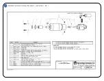
REMOVAL OF #46340 AIR MOTOR DRIVE (SEE PARTS LIST DRAWING PL 46340-190)
1. First make sure the unit is completely disconnected
from the air source.
2. Using a 4 mm Allen wrench, unscrew and remove
both 5 mm socket head cap screws (1) and
respective spring washers (2).
3. You should now be able to lift the air motor drive
REMOVAL/REPLACEMENT OF AIR MOTOR DRIVE COUPLING (ITEM 8 ON PARTS LIST PL 46340-190)
1. If it is necessary to remove the coupling (5) from the
gear motor sub-assembly (11) shaft, tap the
coupling with a rubber or plastic mallet until it
releases from the shaft.
2. To reassemble, align the keyway on the coupling (5)
with the key (6) on the gear motor sub-assembly
(11) shaft and lightly tap the coupling (5) until it
bottoms on the shaft.
Note:
The coupling (5) on the gear motor sub-assembly
(11) shaft has a press fit so the coupling (5) does not
inadvertently come apart during removal or installation
of the gear motor sub-assembly.
REMOVAL OF THE UPPER SHAFT SEAL BODY SUB-ASSEMBLY (4) AND PINION GEAR BUSHING
RETAINER SUB-ASSEMBLY (22) ON PARTS LIST (PL 190DAG & PL 190DAGH) REPAIR KIT (AB-190DAG-
KIT)
1. If it has not already been done, the air motor sub-
assembly should be removed as described in the
Removal of #46340 air motor drive
section above.
2. Next, tap out the groove pin (9), unscrew the upper
shaft seal body sub-assembly (4) and slide off the
shaft (10).
3. Remove gasket (5) from shaft (10).
4. Now unscrew the 5/16” hex head cap screw (19),
remove the lower screw shield (20) and drive plate
(21).
5. Unscrew the pinion gear bushing retainer sub-
assembly (22) and slide off the shaft (10).
6. Pull the rotary Y-housing (14) and bushings (13 &
23) off the stem (12).


