11
4.7 CH1 CONFIGURATION
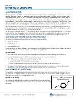
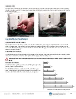
CH1 HIGH VOLTAGE FEEDBACK SETUP
Note:
Ch2 configurations setup are the same as Ch1 con-
figuration setup.
The operator can set the max voltage output in kV for both the
HVPS and PLC.
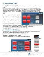
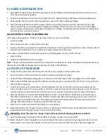
CH1 LINE SPEED SETUP
If you are using a line speed encoder with the ES2500, this con-
figuration will allow you to use the device with the system.
See Encoder Selection for more information about encoders.
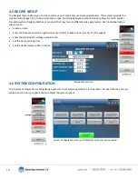
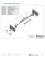
CH1 HV AMPERAGE FEEDBACK SETUP
This screen allows the operator to set an amperage alarm, if
the amperage exceeds this amount the system will fault.
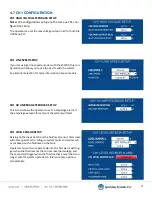
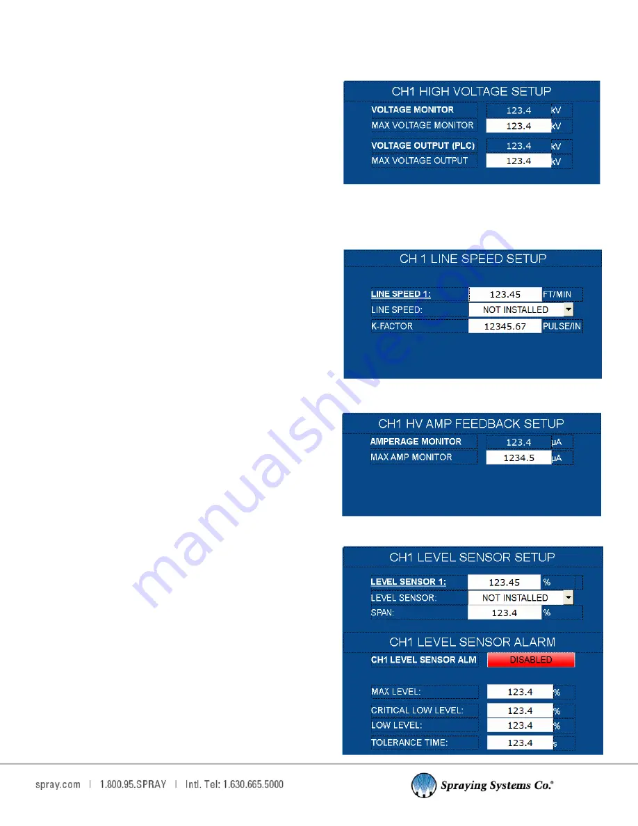
CH1 LEVEL SENSOR SETUP
Relying on the input data from the fluid level sensor, this screen
will allow operators to configure system faults and alarms will
occur based on the fluid level in the tank.
Operators can set two separate alarms, the first alarm will trig-
ger when the fluid reaches the set low level percentage, and
the second will trigger when the fluid reaches a level that is no
longer safe for system operation. A tolerance time option is
also editable.


