27
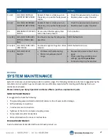
No.
Fault
Cause
Remedy
1 or (2)
CH1 (CH2) COLTAGE
MONITOR NOT WIRED
Detects if there is a broken wire in
the panel, or a possible faulty power
supply
•
Check the panel wired connections
•
Replace power supply if needed
3 or (4)
CH1 (CH2) AMPERAGE
MONITOR NOT WIRED
Detects if there is a broken wire in
the panel, or a possible faulty power
supply
•
Check the panel wired connections
•
Replace power supply if needed
16
EMERGENCY STOP ACTI-
VATED
Occurs when the Emergency Stop
button has been pressed
Pull up button
19 or (21)
CH1 (CH2) TANK LEVEL
CRITICAL (RED FLASH-
ING)
Fluid level is too low for safe pump
operation
Refill the fluid tank
20 or (22)
CH1 (CH2) TANK LEVEL
(RED SOLID)
Fluid level is approaching the critical
setpoint
Refill the fluid tank soon
22 or (23)
CH1 (CH2) DRIVE
ALARM
•
Problems with motor wiring
•
Motor torque/speed out of
range
•
Review and replace cables if dam-
aged
•
Check operating conditions and
settings, specifically
max flow
•
Pump servicing may be required
System maintenance is primarily dependent on system usage. The following maintenance items are suggested by the
manufacturer, but system buyers and operators are ultimately responsible for creating and following their own
maintenance schedule.
Please contact your Spray Specialist and Sales office to purchase replacement parts.
MONTHLY MAINTENANCE
It is suggested to check the following:
•
The grounding wires and electrostatic (HV) cable are free of wear and/or damage
•
All fluid delivery connections
•
Fluid level sensor connections
•
Tightness of the motor and pump coupling screws
•
Pump inlet and outlet connections
•
All manifold sections for leaks or malfunctions
REGULAR MAINTENANCE
Flush the Electrostatic Manifold at the end of each product run.
SECTION 9
SYSTEM MAINTENANCE


