7
6.
Drill out and remove Rivet (9) and slip Trigger (10) out of the Body.
7.
The remaining parts (2, 3, 4, 5) can be removed from Body (6) by gently
pushing the Main Stem, Seat and Pintel sub-assembly (2) towards, and
out of, the front end of Body (6).
8.
These parts (3, 4, 5) can now be removed from Main Stem sub-
assembly (2). If necessary, they should be repaired or replaced with
new ones from #AB63140-KIT repair kit or #AB63140-RBKIT rebuild kit,
respectively.
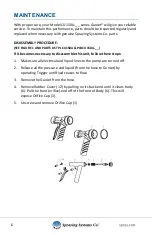
ASSEMBLY PROCEDURE:
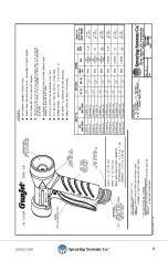
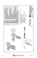
(SEE FIGURE 1 AND PARTS LIST PLCU150A-_ _ & PLBCU150A-_ _)
A. Before reassembling gun apply an O-ring lubricant such as Parker O-lube to
the O-Ring (5).
B. When reassembling the CU150A-AL GunJet (with aluminum body casting),
apply Fel-Pro C5A or similar thread or anti-seize compound to the threads on
Orifice Cap (1).
1.
Place parts (3, 4, 5) in correct order on to Main Stem sub-assembly (2).
2.
Gently push this complete “assembly” in through the front end of Body
(6) with Pintel point of stem sub-assembly towards front of Body (6).
3.
Slip Trigger (10) back into Body (6) with the slot on top of Trigger (10)
engaging the slots on the Main Stem sub-assembly (2). Attach Trigger
(10) to Body (6) with Binding Screw (CP36491-302SS) and Binding Stud
(CP9034-2-302SS) included in the #AB63140-KIT Repair Kit or
#AB63140-RBKIT Rebuild Kit.
4.
Screw Orifice Cap (1) into front end of Body (6) and tighten.
5.
If rubber Cover (12) was completely removed from Body (6), slip handle
part of Cover (12) over grip/handle of Body (6). (Note: Wetting Cover
(12) and Body (6) with soapy water make assembly easier.) Next, pull
front end of Cover (12) over front (orifice) end of Body (6). Finally, pull
back end of Cover (12) over back of Body.
Summary of Contents for GunJet CU150A
Page 1: ...CU150A GunJet Spray Guns USER GUIDE MI CU150A spray com ...
Page 8: ...8 PARTS LIST ...
Page 9: ...9 ...
Page 10: ...10 ...
Page 11: ...11 ...


