6
www.teejet.com
APPLIC
A
TION SE
TUP
SY
STEM SE
TUP
APPENDIX
INTRODUC
TION
OPER
A
TION
845 Sprayer Control System
INST
ALLA
TION
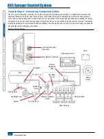
Connect Step 2 - Making The Connection
Now, extend the cable leads to the Flow meter or Pressure Sensor, and GNSS Speed Sensor to the furthest component. Select the
appropriate lead and connect to this component. Run the cable to the other component, taking care to safely secure the cable along the
route.
Refer to the wiring layout on page 5.
Repeat this procedure with the cable leads to the Pressure Regulating Valve and the Boom Control Valves.
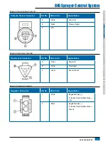
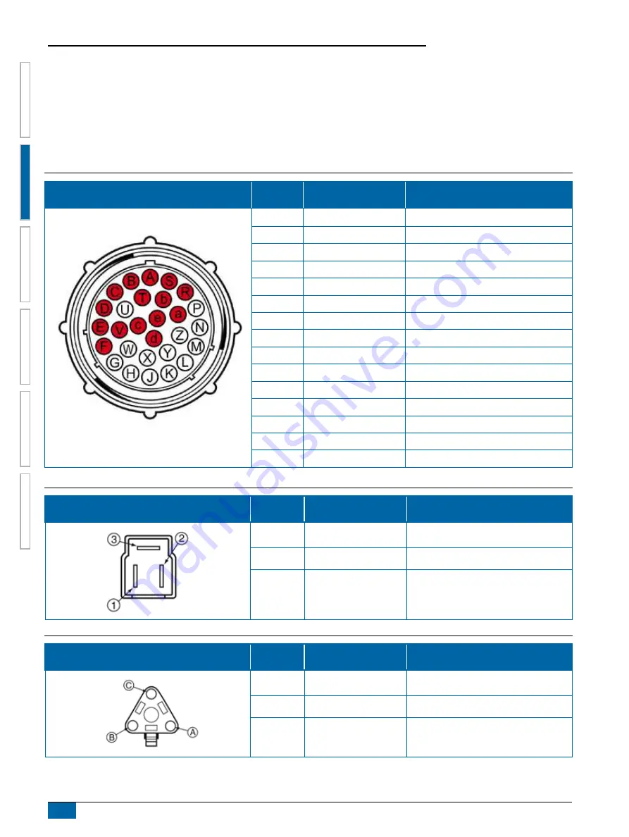
Figure 2-5: Console Connector
Console Connector
Pin No.
Wire Color
Signal Name
A
Blue
Boom Sensor 12v Out
B
White
Boom 1
C
Brown
Boom 2
D
Green
Boom 3
E
Yellow
Boom 4
F
Gray
Boom 5
R
White/Red
Flowmeter
S
White
Pressure Sensor
T
White/Green
Speed Sensor
V
Brown
V) Out
a
White
Regulation Valve (+)
b
Brown
Regulation Valve (-)
c
Blue
+12v Boom Master In
d
Green
Ground
e
Red
Console Power In
Figure 2-6: Power Connector
Power Connector
Pin No.
Wire Color
Signal Name
1
Brown
+12 VDC 845
2
Blue
+12 VDC Master Switch
3
Yellow/Green
Ground
Figure 2-7: Speed Sensor Connector
Speed Sensor Connector
Pin No.
Wire Color
Signal Name
A
Brown
Power Out
B
White
Speed Signal
C
Green
Ground


