APPLIC
A
TION SE
TUP
SY
STEM SE
TUP
APPENDIX
INTRODUC
TION
OPER
A
TION
7
845 Sprayer Control System
98-05349-ENUS R0
INST
ALLA
TION
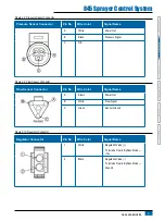
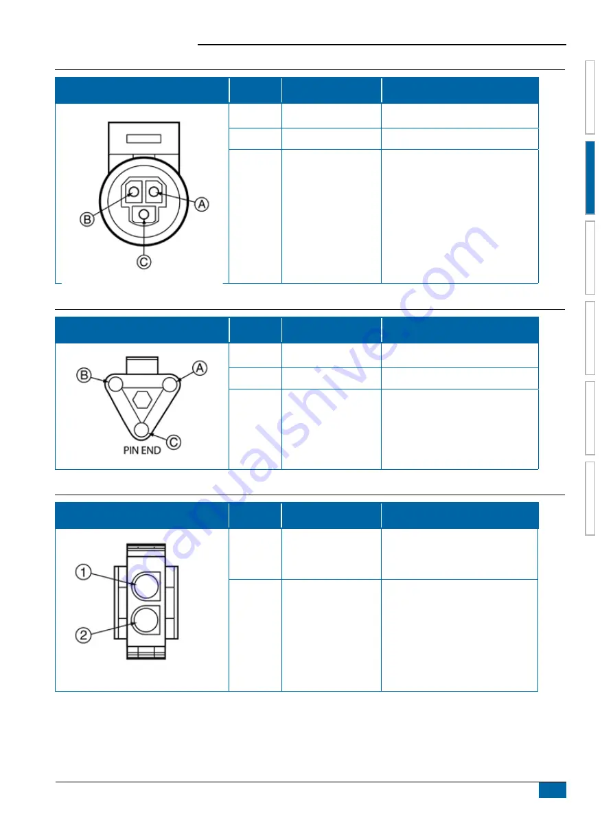
Figure 2-8: Pressure Sensor Connector
Pressure Sensor Connector
Pin No.
Wire Color
Signal Name
A
White
Power Out
B
Black
Pressure Signal
C
N/C
Figure 2-9: Flow Sensor Connector
Flow Sensor Connector
Pin No.
Wire Color
Signal Name
A
Brown
Power Out
B
White
Flow Signal
C
Green
Sensor Ground
Figure 2-10: Regulator Connector
Regulator Connector
Pin No.
Wire Color
Signal Name
1
White
Regulation Valve (+)
To Include Flow in ByPass Mode —
+12v
2
Black
Regulation Valve (-)
To Include Flow in ByPass Mode —
Ground


