INST
ALLA
TION
APPLIC
A
TION SE
TUP
APPENDIX
INTRODUC
TION
OPER
A
TION
11
845 Sprayer Control System
98-05349-ENUS R0
SY
STEM SE
TUP
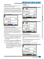
Automatic Calibration
Make sure that the sprayer pump is turned off and that there is
absolutely no pressure in the system (release pressure held by
boom control valves and Tip/Nozzle body check valves).
In some cases, it may be best to remove the sensor from the
plumbing system to complete the calibration.
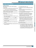
1.
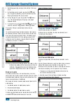
Press and hold the PLUS and MINUS
buttons
simultaneously for 3 seconds to start auto calibration mode.
The lower left portion of the display will count from 1 through 10
during the calibration.
Once the display finishes counting, it should display a number
close to 4.0 (+/- 0.2).
2. To accept the value, press the PROGRAM
button. To edit
the value, use the PLUS button or MINUS
buttons.
Figure 3-9: Zero Pressure Reference Automatic Calibration
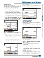
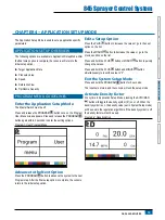
Maximum Pressure Rating
This step is only available if “Pressure Sensor Installed” is set to
“Yes”.
The Maximum Pressure Rating is used to establish the maximum
rating of the pressure Sensor in the system. This number can be
found stamped on the pressure sensor itself.
NOTES: Do not change the value to “0” even if there is no pressure
sensor installed. The Maximum Pressure cannot be set
lower than the Minimum Pressure. The Minimum Pressure
defaults to 10 psi / 0.6 bar, below this value regulation is
stopped.
Figure 3-10: Maximum Pressure Rating
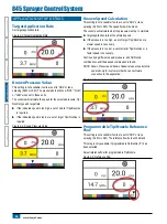
Minimum Pressure
Below the Minimum Pressure value, regulation is stopped, except
when using lane spraying (GLM or LKM).
Figure 3-11: Minimum Pressure
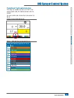
Flow Meter Installed
Select if a flow meter is installed.
If a pressure sensor is not installed this step is automatically set to
“Yes” and cannot be changed.
If lane spraying is selected under Units (GLM or LKM), this setting
will always be set to “Yes” and cannot be changed.
Figure 3-12: Flow Meter Installed
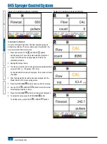
Flow Meter Calibration
This step is only available if “Flow Meter Installed” is set to “Yes”.
Flow Meter Calibration determines the flow meter Pulses based on
a known volume of fluid.
1.
If necessary, run the Automatic Calibration to determine the
number of pulses.
NOTE: The automatic calibration procedure is recommended for
maximum accuracy.
Or note the flow meter calibration number found on the factory
calibrated tag.
2.
Enter the number of pulses.
Pressing the AUTO/MAN
button will switch between normal
value and decimal value (/10). Decimal values can be used with
very low flow calibration values to improve regulation accuracy.


