INST
ALLA
TION
APPLIC
A
TION SE
TUP
SY
STEM SE
TUP
APPENDIX
INTRODUC
TION
27
845 Sprayer Control System
98-05349-ENUS R0
OPER
A
TION
Reset Target Application Rate
Reset the target value to the set rate. See Target Application Rate
in Chapter 4 for details on the set rate.
1. Press the PLUS
and MINUS
buttons simultaneously.
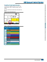
Regulation Indicator
The LED indicator shows when the console is regulating upwards
or downwards (i.e. moving the regulating valve or changing the
PWM). The intensity of the LED light is proportional to the speed of
change.
Examples: In bypass mode, the LED will be green when regulating
upwards or orange when regulating downwards.
In throttle mode, the LED will be orange when regulating
upwards or green when regulating downwards.
Figure 5-9: Regulator Indicator
Automatic Power Down
The console is designed to power itself off after 10 minutes
of inactivity (or at the time specified in the Automatic Power
Down setting in the OEM Setup Mode). This feature keeps the
console from draining the battery on the sprayer, if the operator
inadvertently leaves the console powered on for an extended
period.
Automatic Power Down only occurs when the Master Switch is in
the “Off” position.
To manually power down the console, refer to “Power” in Chapter 1.
NOTE: The Automatic Power Down feature is not available when
the console is in any program mode.
Smart Sensing
With both a pressure and flow sensor installed, the console
determines when the flow rate has dropped below the capacity of
the flow meter being used and will automatically switch to pressure-
based regulation. When the flow rate reaches an acceptable level
for the flow meter to regulate, the console will switch back to flow-
based regulation.


