10
www.teejet.com
BoomPilot
®
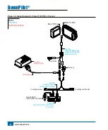
Eagle 8100/8500 or Rangers
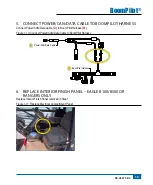
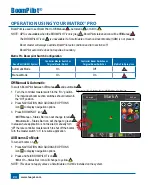
The connection point is at the Junction Box (smaller rectangular box) under the floor to the right of the operator
seat in front of the electrical compartment in the cab. Remove the Interior Finish Panel to access the electrical
compartment.
Figure 1-4: Locate the Connection Point – Eagle 8100/8500 or Rangers
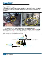
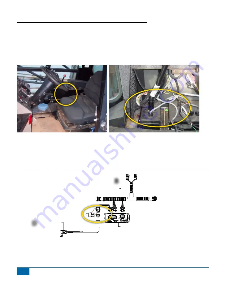
2. connect foot Switch extenSion – air-riDe onLy
Disconnect cap from the Remote ABSC Status Switch connection on the BoomPilot harness
(B)
. Connect the
Foot Switch Extension Cable
(D)
to the Remote ABSC Status Switch connection. Connect extension to foot
switch. The foot switch is used as a spray boom master on/off switch.
Figure 1-5: Connect Foot Switch Extension – Air-Ride Only
PO
W
ER
IN
CAN
RS-232
Po
we
r/D
AT
A
45
-05
62
6
45-05626
Power/CAN/Data Cable
(included with FieldPilot
and BoomPilot kits)
10A Fuse
to RS-232
CAN
Tilt Gyro
Module (TGM)
TGM Harness
78-05077
BoomPilot Section Driver Module
(15 sections)
45-05740
BoomPilot Harness
Air-Ride w/ MT Controller
45-05868
Cable, Extension
to Foot Switch
Remote ABSC
Status Switch Connection
to existing Air Ride harness
to existing Air Ride harness
A
IR R
ID
E
ON
LY
45-05868 xx/xx
Matrix Pro 570G
Matrix Pro 840G
Matrix
BoomPilot
Optional Accessory
B
D

