background image

14

www.teejet.com

BoomPilot

®

7.  coMpLete eLectronic inStaLLation

Refer to the “Configuration Using your Matrix

®

 Pro” and “Operation Using your Matrix

®

 Pro” sections of this manual 

for further instructions on setting up and using your Matrix Pro for ABSC. 
If not using a Matrix Pro, please refer to the owner’s manual supplied with the guidance system to complete the 

electronic installation and setup.

operation Review and tips

Off/Manual & Automatic

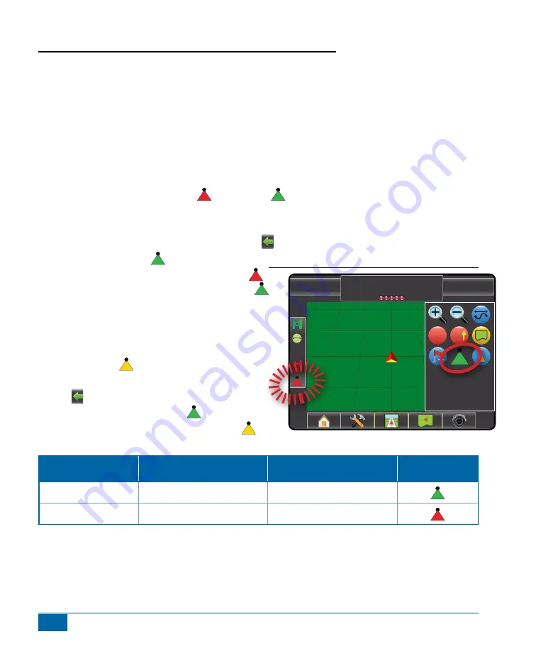
To switch BoomPilot between off/manual   and automatic  :
1.  Turn the controller master switch to the “On” position. The individual boom section switches should remain in 

the “Off” position. 

2.  Press NAVIGATION AND GUIDANCE OPTIONS icon   to display navigation options.

Figure 1-12: Automatic to All Booms On Mode

0.0 mph

0.00 ac

Mark a

A

A

3.  Press BOOMPILOT icon  .

◄Off/Manual – Status Bar Icon will change to red 

◄Automatic – Status Bar Icon will change to green 

In areas where application is not desired, manually turn 

“off” the rate controller master switch to shut off the booms. 

Turn the master switch “on” to resume application. 

All Booms On Mode

To turn all booms on  :
1.  Press NAVIGATION AND GUIDANCE OPTIONS  

icon   to display navigation options.

2.  Press and hold BOOMPILOT icon  .

◄All On – Status Bar Icon will change to yellow 

Matrix Pro Boompilot Switch Configuration

BoomPilot (ABSC) System

Controller Master Switch or  

Original Master Switch

Controller Boom Switches or 

Original Boom Switches

Matrix Pro Spray Icon

Automatic Mode

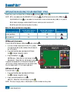
On

Off

Manual Mode

On

On

•  System will still operate normally using existing section switches if BoomPilot is in manual
•  Boom master will always override BoomPilot auto condition and turn sections off
•  BoomPilot auto mode does not require a boundary
•  If typical application is a first lap around the field, make this lap with BoomPilot in manual mode to avoid 

improper on/off boom action during reversing movements of vehicle if BoomPilot is in auto. 

Summary of Contents for TeeJet BoomPilot 90-02671

Page 1: ...B o o m P i lot Install ation MANUAL Automatic Boom Section Control Installation Manual for Kit Number 90 02671 For use with Willmar w Mid Tech Controls Air Ride Eagle 8100 8500 or Rangers...

Page 2: ......

Page 3: ...OF PROFIT LOSS OF USE OR DATA INTERRUPTION OF BUSINESS OR FOR INDIRECT SPECIAL INCIDENTAL OR CONSEQUENTIAL DAMAGES OF ANY KIND EVEN IF TEEJET TECHNOLOGIES HAS BEEN ADVISED OF SUCH DAMAGES ARISING FRO...

Page 4: ...onnect SDM 12 5 Connect Power CAN Data Cable to BoomPilot Harness 13 6 Replace Interior Finish Panel Eagle 8100 8500 or Rangers Only 13 7 COMPLETE ELECTRONIC INSTALLATION 14 Operation Review and Tips...

Page 5: ...5 BoomPilot 98 05275 R0 Overlap 22 Delay On 22 Delay Off 23 Operation Using your Matrix Pro 24 Off Manual Automatic 24 All Booms On Mode 24 Example 25 BoomPilot Status 25...

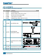
Page 6: ...ver Module SDM 1 D 45 05868 Cable Extension to Foot Switch 1 E 98 05275 Installation Manual Willmar w Mid Tech Controls 1 Item Part Description Illustration A 45 05626 Power CAN Data Cable POWER IN CA...

Page 7: ...to RS 232 CAN Tilt Gyro Module TGM TGM Harness 78 05077 BoomPilot Section Driver Module 15 sections 45 05740 BoomPilot Harness Air Ride w MT Controller 45 05868 Cable Extension to Foot Switch Remote...

Page 8: ...G 45 05626 Power CAN Data Cable included with FieldPilot and BoomPilot kits 10A Fuse to RS 232 CAN Tilt Gyro Module TGM TGM Harness 78 05077 BoomPilot Section Driver Module 15 sections 45 05740 BoomPi...

Page 9: ...ght are stated as if the user is seated in the driver s seat NOTE BE VERY CAREFUL TO ABSOLUTELY SECURE ALL CABLES AND HOSES SO THAT THEY DON T INTERFERE WITH THE MANY MOVING PARTS OF THE MACHINE 1 Loc...

Page 10: ...tension Cable D to the Remote ABSC Status Switch connection Connect extension to foot switch The foot switch is used as a spray boom master on off switch Figure 1 5 Connect Foot Switch Extension Air R...

Page 11: ...to valve harness or junction box 3 Connect BoomPilot harness B to controller harness 4 Air Ride Only Connect BoomPilot Harness extension wire from step 2 to the cold switch side 12v ON 0v OFF of the...

Page 12: ...omPilot Harness B Figure 1 9 LED Description Section Power On boom section power is on Off boom section power is off In Out Error Off boom output is high or on Blinking boom output is low or off Auto...

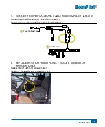
Page 13: ...ot Harness B Figure 1 10 Connect Power CAN Data Cable to BoomPilot Harness POWER IN CAN RS 232 Power DATA 45 05626 Power CAN Data Cable BoomPilot Harness 6 Replace Interior Finish Panel Eagle 8100 850...

Page 14: ...Status Bar Icon will change to green In areas where application is not desired manually turn off the rate controller master switch to shut off the booms Turn the master switch on to resume applicatio...

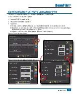
Page 15: ...mber of boom sections guidance width spray width overlap percentage implement delay on time and implement delay off time Lightbar used to establish LED brightness LED mode and LED spacing Figure 1 13...

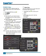
Page 16: ...CONFIGURATION side tab to return to the main Configuration screen NOTE All settings under Vehicle Setup are required for autosteer and tilt sensor operation as well as proper implement operation Figu...

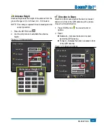
Page 17: ...le Type Ant Height Dir to Boom Dist to Boom Antenna Height ft 1 2 3 12 50 Clear 4 5 6 7 8 9 0 Direction to Boom Direction to Boom sets whether the boom is located behind or in front of the GPS antenna...

Page 18: ...e is 0 0 164 0 feet 0 0 50 0 meters 1 Press the KEYPAD icon 2 Use the entry screen to establish the distance from the GPS antenna to the boom Figure 1 19 Distance to Boom Config Vehicle 12 50 ft 0 00...

Page 19: ...Width used to enter the width between the guidelines Spray Width used to enter the width of each implement section Overlap used to select the amount of overlap allowed when the boom sections are turne...

Page 20: ...boom sections on the implement Figure 1 21 Number of Boom Sections Config Implement Num Sections Spray Width Guidance Width 75 00 ft 75 00 ft 15 7 8 9 10 11 12 13 14 15 Guidance Width Guidance Width...

Page 21: ...er 1 Press the KEYPAD icon 2 Highlight the section to be established 3 Press the KEYPAD icon 4 Use the entry screen to establish the spray width 5 Repeat steps 2 to 4 until all sections have been esta...

Page 22: ...ns as a look ahead for establishing the timing for the boom section valves to switch on exactly when entering an area that has not been applied If the boom turns on too soon when entering a non applie...

Page 23: ...turns off too soon when entering an applied area decrease the Delay Off setting If the boom turns off too late when entering an applied area increase the Delay Off setting Range is 0 0 10 0 seconds 1...

Page 24: ...ual Automatic To switch BoomPilot between off manual and automatic Figure 1 27 Automatic to All Booms On Mode 0 0 mph 0 00 ac Mark A A A 1 Turn the controller master switch to the On position The indi...

Page 25: ...i activate automatic mode on BoomPilot iii turn master On iv begin operation for remainder of field performing guidance functions as desired BoomPilot Status BoomPilot Status displays information rega...

Page 26: ......

Page 27: ......

Page 28: ...c installation kits have been developed to work in conjunction with your automated boom section control system This kit contains the necessary components and instructions to install ABSC on a Willmar...

Reviews: