6
MAINTENANCE
With proper care, your PW4000A GunJet
®
will give you reliable service. To
maintain this performance, parts should be inspected regularly and replaced
when necessary with genuine
Spraying Systems Co.
parts.
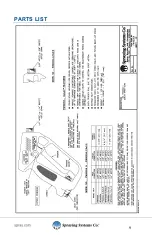
DISASSEMBLY PROCEDURE:
(SEE FIGURES 1 & 2 ON PAGE 9)
If it becomes necessary to rebuild the Valve Assembly (3 - 13) order Spare Parts
Kit ABPW4000A-KIT or ABPW4000AW-KIT, follow these steps:
1.
Make sure all air, electrical and liquid lines to the pump are turned off.
2.
Release all the pressure and liquid (from the hose to GunJet) by
operating Trigger until fluid ceases to flow.
3.
Set Trigger Lock (17) in locked position.
4.
Remove spray gun from hose.
5.
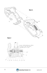
Remove the five Screws (19) and Housing (18). See Figure 1, Page 9.
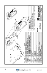
6.
Lift out all internal parts, leaving all parts assembled. Trigger Lock (17)
should remain in Housing (18).
7.
Clamp the Valve Body (2) and remove Retaining Screw (4) containing
Gasket (5), Back-Up Ring (6) and O-ring (7). See Figure 2, Page 9.
8.
Remove Stem (9), Valve Seat (8) with Back-Up Ring (11) and O-ring (12),
as well as Ball (10) and Spring (13).
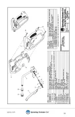
PARTS REPLACEMENT/ASSEMBLY PROCEDURE:
(SEE FIGURES 1 & 2 ON PAGE 8)
1.
Install new Back-Up Ring (11) and O-ring (12) on new Valve Seat (8).
2.
Clamping Valve Body (2) insert the following new parts: Spring (13), Ball
(10) and Valve Seat Sub-Assembly (8, 11 & 12) into Valve Body.
3.
NOTE: Cross-drilled holes in Valve Seat (8) should be in line with inlet
of valve body to minimize pressure loss. See “Figure 2”.
4.
Remove Gasket (5), O-ring (7), and Back-up Ring (6), from Retaining
Screw (4) and replace with new parts.
Summary of Contents for GunJet PW4000A
Page 1: ...PW4000A GunJet Spray Gun USER GUIDE spray com MI PW4000A...
Page 8: ...8 Figure 1 Figure 2...
Page 9: ...9 PARTS LIST...
Page 10: ...10...
Page 11: ...11...


