7
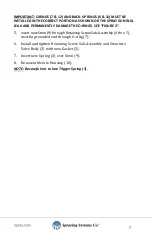
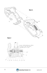
IMPORTANT: O-RINGS (7 & 12) AND BACK-UP RINGS (6 & 11) MUST BE
INSTALLED IN THE CORRECT POSITION AS SHOWN OR THE SPRAY GUN WILL
LEAK AND PERMANENTLY DAMAGE THE O-RINGS. SEE “FIGURE 2”.
5.
Insert new Stem (9) through Retaining Screw Sub-Assembly (4 thru 7),
inserting rounded end through O-ring (7).
6.
Install and tighten Retaining Screw Sub-Assembly and Stem into
Valve Body (2) with new Gasket (5).
7.
Insert new Spring (3) over Stem (9).
8.
Re-assemble into Housing (18).
NOTE: Be careful not to lose Trigger Spring (3).
Summary of Contents for GunJet PW4000A
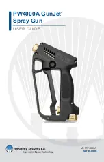
Page 1: ...PW4000A GunJet Spray Gun USER GUIDE spray com MI PW4000A...
Page 8: ...8 Figure 1 Figure 2...
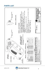
Page 9: ...9 PARTS LIST...
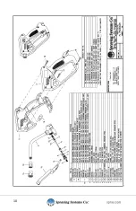
Page 10: ...10...
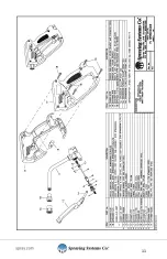
Page 11: ...11...

