background image


   |    / /


INSTALLATION 

FLUID CONNECTIONS: 

Fluid connections should be made using the appropriate 1/8” pipe connection. If a 

metal fitting is used, appropriate thread sealer should be applied to the threads 

prior to assembly. For those applications requiring recirculation,  

two 1/8” pipe connection ports are provided. If recirculation is not required, one 

of the ports should be plugged using 1/8” pipe plug which is provided with each 

unit. 

ELECTRICAL CONNECTIONS: 

Electrical conduit connection for conduit fitting accepts 1/2” NPT (M) for NPT 

version. The conduit must protect the electrical cable from mechanical damage 

and terminate in a sealed enclosure or junction box appropriate for the hazardous 

location. For BSPT version, an Ex d rated cable gland is used with cable. The fuse 

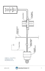
holder and a 3/10-amp fuse should be used as shown in Figure 1. The ground 

connection of the PulsaJet® 10000AUH-03-Z1 must be attached to a true ground.  


Summary of Contents for PulsaJet 10000AUH-03-Z1

Page 1: ...PulsaJet 10000AUH 03 Z1 USER GUIDE spray com MI 10000AUH 03 Z1 for NPT BSPT Models...

Page 2: ...ned tasks US installations shall comply with the relevant requirements of the National Electrical Code ANSI NFPA 70 European installations shall comply with the relevant requirements of EN 60079 14 Ma...

Page 3: ...temperature and chemical resistance SPECIFICATIONS Power Requirements 27VDC Max 0 30 AMPS Max Inlet connections 1 8 NPT for AA10000AUH 03 Z11 8 BSPT for AAB10000AUH 03 Z1 Electrical conduit connectio...

Page 4: ...uld be plugged using 1 8 pipe plug which is provided with each unit ELECTRICAL CONNECTIONS Electrical conduit connection for conduit fitting accepts 1 2 NPT M for NPT version The conduit must protect...

Page 5: ...5 FIGURE 1 ELECTRICAL SCHEMATICS FOR AA10000AUH 03 Z1 AutoJet 24VDC based controller or other appropriate solenoid driver...

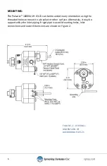
Page 6: ...ation using the threaded holes to mount to a bracket or other surface Alternately it may be supported by the inlet piping if rigid pipe is used Mounting holes inlet connections and outer dimensions ar...

Page 7: ...ch it is used FLUID SUPPLY Make sure maximum pressure rating of 100 psi 7 bar is not exceeded To help prevent clogging problems the fluid supply line needs to include a line strainer MAINTENANCE All p...

Page 8: ...spray tip Remove spray tip and clean orifice or replace tip Debris in fluid passages Disassemble nozzle and clean fluid passages Plunger not operational Check coil for nominal resistance of 67 Ohms If...

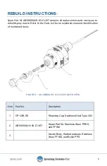
Page 9: ...r to the Parts List for an exploded view and identification of numbered items FIGURE 3 AA10000AUH 03 Z1 EXPLODED VIEW Item Part No Description 1 CP1325 SS Retaining Cap Stainless Steel Type 303 2 AB10...

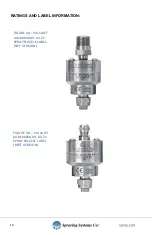
Page 10: ...10 RATINGS AND LABEL INFORMATION FIGURE 4A PULSAJET AA10000AUH 03 Z1 SPRAY NOZZLE LABEL NPT VERSION FIGURE 4B PULSAJET AAB10000AUH 03 Z1 SPRAY NOZZLE LABEL BSPT VERSION...

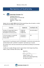
Page 11: ...EN 60079 18 FM10ATEX0040X1 The Electromagnetic Compatibility Directive 2014 30 EU of 26 February 2014 EN 61000 6 4 EN 61000 6 2 N A As per Article 14 and Annex II and III of 2014 30 EU a technical co...

Page 12: ...Avenue and Schmale Road P O Box 7900 Wheaton IL 60187 7901 Tel 1 800 95 SPRAY Intl Tel 1 630 665 5000 Fax 1 888 95 SPRAY Intl Fax 1 630 260 0842 www spray com MI 10000AUH 03 Z1 rev 3 Spraying Systems...

Reviews: