background image


13 


The following check ups should be carried out at regular 12 months intervals: 


11.1  Rotor blades 

 
Check if the blades show damages like broken edges, damaged surface or cracks. If 
you  notice  any  damage,  the  generator  must  not  be  used  any  longer.  Check  the 
screwing one day after mounting and after that every 3 months. Eventually that you 
can turn to a longer interval. 


11.2  Srews 

 
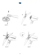
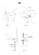
Check that all accessible screws are correctly fixed. Especially the hexagon srews of 
the  connection  to  the  hub,  the  central  shaft  nut  and  the  fixing  of  the  mast  must  be 
checked (see page 10, 11 and page 17, sketch 4, 5 ,6 ,7 and page 18, sketch 8, 9). 


11.3  Bearings and gaskets 

 
The bearing of the generator shaft and the bearing of the yaw shaft are permanently 
lubricated.  Please  check  these  bearings  as  to  free  movement,  bearing  play  and 
watertightness. Deficient bearings must be replaced. 


11.4  Corrosion protection 

 
The complete housing is made of seaworthy alumine and additionally powder coated. 
If the outer layer is damaged, there is a risk of corrosion. Please paint these spots 
with suitable varnish (RAL9010) 


11.5  Mounting construction 

 
Check this construction in line with the instructions concerned (optional). 


11.6  Electrical system 

 
Please first stop the Silentwind generator so that all wires carry no voltage. Check if 
all  connections  are  properly  fixed  and  not  corroded.  Possible  corrosions  must  be 
removed  and  treated  with  contact  spray.  Give  special  attention  to  the  battery 
connections: they must be clean and greased with vaseline. Check the battery in line 
with  the  instructions  of  the  producer  and  (if  necessary)  refill  with  destilled  water.  In 
case more than 1 battery is used check that all batteries have the same capacity and 
state of charge. 
 

Summary of Contents for Silentwind

Page 1: ...instructions for use installation manual SILENTWIND...

Page 2: ...ailability of electric energy without the possibility of grid connection is essential Fair winds at any time The Spreco Team Please note that this manual is part of the product and must be read closel...

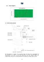
Page 3: ...nical data 7 3 3 Dimensions 7 3 4 Power diagram 8 4 List of enclosed parts 8 5 Operation description 9 6 Diameters of cables 9 7 Installation 9 8 Getting started 11 9 Run and stop 12 10 Charging indic...

Page 4: ...d carbon fiber blades were successfully tested in a wind tunnel up to wind speeds of 35m s 63 knots according to DIN EN 61400 2 Therefor you need not worry about the Silentwind generator in any storm...

Page 5: ...Never ever touch the open end of the wires The currents on charging the batteries can reach more than 30 A DC The whole wiring electric components and connection points must be able to carry a current...

Page 6: ...C Rated power 400 Watt Rated peak power at 13 5 m s Start up speed 2 2 m s Start of charging 3 m s Charge indicator Blue LED on the buttom of housing 3 1 2 Mechanical date Safety test in wind tunnel 1...

Page 7: ...ge 12 24 VDC Max input current windgenerator 30 A Max input current solar 10 A 100Wp LCD LED displays W V A kWh Ah load data 3 2 2 Mechanical data weight 1 15kg regulator Package dimensions 190x120x65...

Page 8: ...parts All information is reliable The producer does not take any resonsibility for inaccuracies The user of both the instructions and the product takes any responsibility and any risk All specificatio...

Page 9: ...equivalent of sonic velocity at the tips of the blades For every day use and safety reasons we have equipped the charge regulator with an additional electronic and manual stop switch 6 Diameters of c...

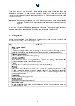
Page 10: ...ice Once the mast is mounted you can start the relatively simple installation of the Silentwind generator First connect the 3 CF blades to the assembly hub see page 17 sketch 4 with the enclosed srews...

Page 11: ...ntrolle Mast construction Optional check according to instruction especially all srew connections bracing vertical position Grounding and lightning protection according to local regulations Electric i...

Page 12: ...ator A blue LED at the bottom of the body shows you when the charging process starts This depends on the state of charge of the battery normally 12 5 volt Attention If you operate the system with a 3...

Page 13: ...bearings as to free movement bearing play and watertightness Deficient bearings must be replaced 11 4 Corrosion protection The complete housing is made of seaworthy alumine and additionally powder co...

Page 14: ...th instruction Generator shaft sluggish Turn manually Connection windgenerator charge regulator short circuit of AC cables short circuit of generator customer service Windgenerator doesn t charge Poss...

Page 15: ...iences Charge regulator wrongly installed Check in line with manual Correct installation Charge regulator stop switch is in position stop Switch stop switch in position RUN Observe manual instructions...

Page 16: ...16 14 Attachment sketches sketch 1 sketch 2 sketch 3...

Page 17: ...17 sketch 4 sketch 5 sketch 6 sketch 7...

Page 18: ...18 sketch 8 sketch 9 sketch 10 sketch 11...

Page 19: ...ill have to prove that the windgenerator has been mounted to an appropriate mast construction Damages caused by acts of nature beyond control Spreco Lda cannot be held responsible for especially light...

Page 20: ...20 Notice...

Page 21: ...rialnumber windgenerator Seriennummer Laderegler Serialnumber charge controller Verk ufer Firmenstempel Unterschrift Purchaser company stamp signature Kaufdatum date of purchase Die genauen Garantie B...

Reviews:

Related manuals for Silentwind