background image

PART

NO

QTY

2

L02E

22

L05A

L02E

Y6

4

M4.2X16

Z01

Z01

L02E

L02E

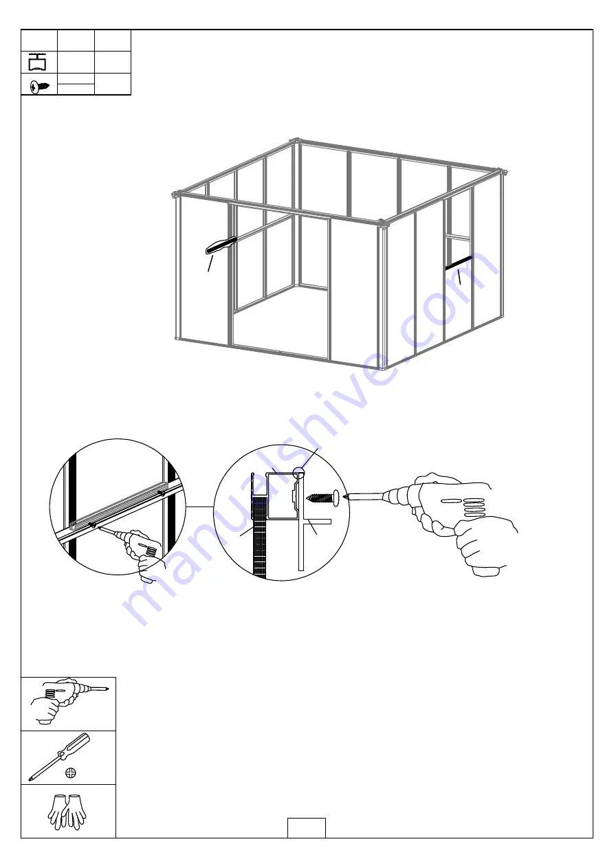
Insert another end of Y6 into the channel of each L02E, 
and then align L02E & L05A, use Z01 to secure them

with the powered screw-driver.

Keep L05A flush to L02E.

*Please ensure L02E and L05A are flush & aligned. 

Summary of Contents for SMALL GAZEBO

Page 1: ...MODEL PRODUCT SIZE LxWxH 295x295x270cm PLEASE READ CAREFULLY BEFORE ASSEMBLY SMALL GAZEBO Assembly Instructions Gazebo Glasshouse ...

Page 2: ...nd on the roof Heavy articles should not be leaned against the greenhouse 5 Keep the roof and gutter clear of snow dirt leaves Allowing snow to build up on the roof may damage the product 6 Unlike steel if the paint finish is scratched this will not harm the aluminium underneath 7 When your product needs cleaning use a mild detergent solution and rinse with cold clean water Do not use acetone abra...

Page 3: ...ns and Features 1 Compared with traditional greenhouses this new product features many significant improvements The hollow box profile aluminium framing is much stronger than other greenhouses and it can withstand much greater pressure 3 Our unique frame connectors make much stronger joints than conventional greenhouses 4 The strong two part eaves beam includes an integral gutter Downpipes are als...

Page 4: ...th the roof vents If required automatic roof vent openers are available as an inexpensive optional extra 6 Each Polycarbonate Panel comes with UV protected properties Please ensure the clear film with the text faces out toward the sun Remove both films before installation of the panels ...

Page 5: ...white film facing inside and the clear film with writing facing the sun If you have any questions please feel free to contact us Head Office Mon Fri 9am 4pm 14 Crown Street South Geelong VIC 3220 PH 1300 657 174 Support sproutwellgreenhouses com au POLYCARBONATE ORIENTATION WRITING FACES THE SUN X 5 ...

Page 6: ...8 8 W07 4 Ø4X14D Z02 175 M4 2X16 Z01 J01 4 J02 4 4 W03 W08 2 W21 4 4 W22 1 W23 1 W24 W05 14 J06 4 J07 4 J08 4 L25 4 202 M5X12 S01 26 M5X12 S02 8 M4 2X16 Z03 M8 M01 2 W06 2 S03 14 M8X60 PART NO QTY 4 L05E 1 L05F S04 M6X12 6 6 M02 M6 A 8 SMALL GAZEBO ALU Box No 1 ALU Box No 1 ...

Page 7: ... 2 L20 2 L11 2 L15A 2 PART NO QTY 4 L03D 4 L05C 2 L05B 2 L02E 1 L24 PART NO QTY L03A 9 L16A 1 L18A 2 L18B 2 1 L18C 1 L18D L17 2 L05G 4 L16B 1 L03B 4 4 L03C ALU Box No 2 Door Assembly Vent Assembly x 2 SMALL GAZEBO ALU Box No 2 ...

Page 8: ...Y3 Y3 Y3 Y4 Y4 Y4 Y6 Y6 Y7 Y7 Y10 Y10 Y11 Y11 Y11 Y11 4 4 Y2 Y1 Y3 Y4 4 4 Y6 2 Y7 2 PART NO QTY 126M J11 PART NO QTY 79M J11 PC Glass NO 1 Rubber Sealing for Walls Roof Provided for Glass Panels only Rubber Sealing for Walls Only Provided for Glass Panels only PC Glass Box No 1 SMALL GAZEBO ...

Page 9: ...01 L19B W06 W06 1 W06 Vent Assembly 322MM 322MM Install Vent Arm W06 in the middle of L19B 322mm from each end Screws position Screws position Insert Connector B W07 into each end of the profiles L19A L19B L20 and then Please ensure there is no gaps between each profile mark the distance from each end about 20MM Lastly secure them with screws Z01 ...

Page 10: ... QTY L11 1 L15A 1 10 2 M4 2X16 Z01 L11 L15A 1 1 2 2 Z02 Z01 2 Ø4X14D Z02 Y10 J11 J11 PART NO QTY 2 65M J11 1 2 Insert the Rubber J11 between Glass panels and Profiles as shown below Not Provided for PC panels ...

Page 11: ...S04 S04 M02 M02 L05G L05G A A A A L16B L18D L18A L18B Y11 Y11 S04 M6X12 6 6 M02 M6 L05G 4 S01 L16B 1 Left Door Assembly 1 1 2 L17 Insert Connector A into each end of the profiles L16B L18A L18B L18D and then mark the distance Lastly secure them with screws Z01 using the powered screw driver from each end about 20 30MM 1 2 ...

Page 12: ...5G L05G L17 Y11 Y11 S04 S04 M02 M02 S01 Right Door Assembly 1 1 2 Insert Connector A into each end of the profiles L16A L18A L18B L18C and then mark the distance Lastly secure them with screws Z01 using the powered screw driver from each end about 20 30MM 1 2 A ...

Page 13: ...13 PART NO QTY 12 2M J11 J11 J11 Y11 Insert the Rubber J11 between Glass panels and Profiles as shown below Not Provided for PC panels ...

Page 14: ...a b a b a b a b 14 10mm It is essential the dimensions a b are the same to ensure the base is square Support at the corners only is inadequate Expansion Screw Concrete Ground ...

Page 15: ...M i n n e r Door 352 705 705 705 352 352 705 705 352 352 352 352 705 705 352 705 705 0 1 2 3 25 2949MM outer 2949MM outer 4 1 7 0 5 M M o u t e r Expansion bolts assembly Door This shows a layout for W05 s positions where it is placed in the middle of the panel for each section ...

Page 16: ... 4 16 J02 4 L08A J02 L01A 4 L08A L08A L08A L08A J02 J02 J02 J02 0 1 2 3 0 1 2 3 L01A 8 M5X12 S01 L01A L01A L01A L01A S01 Insert the J02 into L08A as shown Install L01A onto each L08A through the J02 using the screw S01 ...

Page 17: ...1 J01 J01 L07A L07A L07A 0 1 2 3 0 1 2 3 S01 8 M5X12 S01 J01 4 Insert the joint J01 into L01A from the top then connect each L07A Lastly secure all parts using the screw S01 Please ensure all parts are in correct angle before tightening up screw S01 ...

Page 18: ... Secure them with screw S01 Lastly slide the last Panel Y5 from the top into But if using PC Panels you can install all the L03A firstly and then slide PC Panels in Insert the first Panel Y5 into the channel of L01A Do the same for another 2 sections the channels of L01A L03A as shown below This shows the correct way to install Glass Panels ...

Page 19: ...O QTY L03A 6 19 6 24 M5X12 S01 Y5 L03A L03A L07A L08A Y5 Y5 Y5 Y6 Y6 2 Y6 L03A L03A S01 S01 The last panel Side Wall Assembly Repeat the sequence as per Y6 is the last panel to slide in the Back Wall Assembly ...

Page 20: ...B L07A L08A L04A L04B L04A L04B L05B L05B L04A L04B L 01A L05B S01 S01 S01 S01 16 M5X12 S01 2 Y5 Do the same as Back Wall Assembly Front Wall Assembly to install L04A L04B and Y5 using the screw S01 Then install L05B onto L01A L04A L04B using the screw S01 ...

Page 21: ... 90 90 0 1 2 3 0 1 2 3 L05A L05A L05A Use the screw S01 to secure each end of 3 x L05A onto each L01A and then use Z01 to install the rest part of L05A onto each L03A Do not over tighten Z01 as you don t want the screws to strip with the powered screw driver Please ensure all parts are in correct angle before securing L05A ...

Page 22: ...Y6 4 M4 2X16 Z01 Z01 L02E L02E Insert another end of Y6 into the channel of each L02E and then align L02E L05A use Z01 to secure them with the powered screw driver Keep L05A flush to L02E Please ensure L02E and L05A are flush aligned ...

Page 23: ...1 2 Mark on L03A through the holes of bracket W03 at distance 643MM from L02E as shown in FIG 2 Do the same on the other end 3 Use Z01 to fix the vent onto L03A as shown in FIG 1 4 Insert Y7 into the channel of each L03A 1 1 2 2 Place W06 W08 in correct location and then use Z01 to secure W08 onto L05A The W06 should close over both pins in the W08 to be in correct location 23 ...

Page 24: ...PART NO QTY 61M J11 24 J11 J11 J11 Insert the Rubber J11 between Glass panels and Profiles as shown below Not Provided for PC panels ...

Page 25: ...oof Assembly L07A W21 S01 Use the bracket W23 to connect 4 X L23A as shown then secure them with S01 bolts Outside View Inside View Use the bracket W21 to connect the roof profiles L23A and the eave profiles L07A then secure them with S01 Two persons at least are needed to complete this assembly ...

Page 26: ... 2 W24 W24 M01 L03D Install 4 x L03D on the roof as shown and secure them with S01 Twist M01 into the bolt on the cap bracket W24 and then insert the bolt on W24 through W23 Adjust the position of the top M01 to allow enough space for the bottom M01 to tighten it up W23 ...

Page 27: ...QTY 46 2M J11 W22 27 Use the bracket W22 to connect L03B L03C and secure them with S01 Then slide Y1 Y2 in place 8 2 6 8 8 2 6 8 Please ensure the orientation of Y1 Y2 is correct when panel assembly The longer edge 826 8MM should be placed vertically as shown Insert the Rubber J11 between Glass panels and Profiles as shown below Not Provided for PC panels ...

Page 28: ...28 J11 J11 Y4 Y3 Y4 Y3 Slide Y3 Y4 in Insert the Rubber J11 between Glass panels and Profiles as shown below Not Provided for PC panels ...

Page 29: ...her sides Install the gutter profile L09A once all panels are completely inserted Then tap L09A gently into the channel of L07A with a rubber mallet Do the same on the other side Ensure none of the glazing panels move or slide back during this process ...

Page 30: ... L03B L03C S01 L05C L03B L03C S01 4 L05E 2 Z01 L03D 1 3 56 M4 2X16 Z01 Z01 1 L05F Bracing Assembly L05F Use S01 to secure each roof brace L05C onto L03B L03C at each end then use Z01 to secure them onto L03D in the middle Use Z01 to secure each eave brace L05E L05F ...

Page 31: ...Door Right Door 1 1 1 1 1 L24 L25 4 3 M4 2X16 Z01 Z01 L04A 2 x Z03 Door Assembly L24 Use S02 to install 4 x Door Hinges L25 onto each door profile and L04A L04B then secure them with Z03 as shown below 6 x S02 2 x Z03 L04B 6 x S02 L24 Use 3 x Z01 to secure L24 onto L07A ...

Page 32: ...8 4 4 M4 2X16 Z01 J06 J01 32 Downpipe Assembly Use Silicone to avoid leaking Drill a hole in L01A roughly 3MM diameter 700MM distance from the bottom Use Z01 to secure the bracket J08 and then clip the downpipe J06 into the bracket J08 not provided ...

Reviews: