7
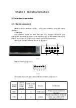
Signal
IDC10 pin socket cords
number
A
7
B
9
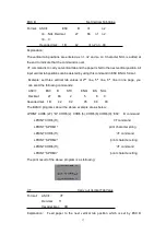
3-3 485 interface pin definition
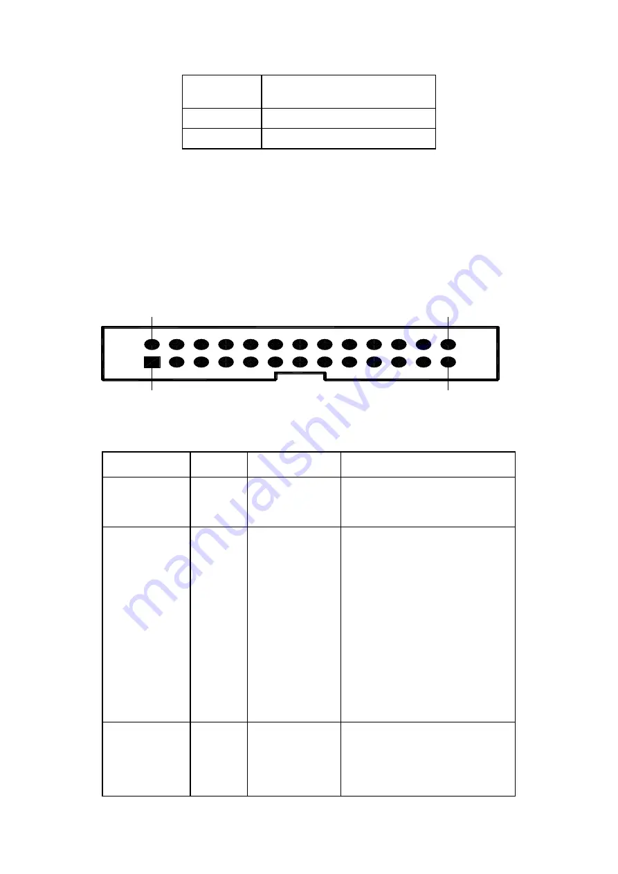
3.1.2 Parallel interface connection
RMD12 printer’s parallel interface is compatible with CENIRONICS,
whose interface socket is 26 lines flat cable or replace model. Parallel interface
pin number shown as below:
1
2 5
2 6
2
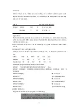
3-4 Parallel interface pin number
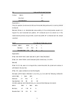
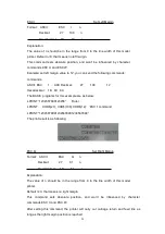
Parallel interface pin number definition shown as below:
Cords No.
Signal
Direction
Instruction
1
/STB
input
Gate trigger, rising along the
read data.
3
5
7
9
11
13
15
17
DATA1
DATA2
DATA3
DATA4
DATA5
DATA6
DATA7
DATA8
Input
Input
Input
Input
Input
Input
Input
input
Those signals represent the
message from 1 to 8, when
the logic is “1” of each
signal,it is high level, logic
show”0”mean low level.
19
/ACK
output
Pulse reply,” low” level mean
the date has been received
and printer already to receive
Summary of Contents for SP-RMD12
Page 39: ...37 n 2 Off line status n 3 Error status n 4 paper feeding status...
Page 47: ...45 Characters Set 2...
Page 48: ...46...


