background image

13

the fluid cooler fan, execute one of the two alternative biocidal treat-
ment programs described in the following:

•  Resume  treatment  with  the  biocide  which  had  been  used  prior 

to shutdown. Utilize the services of the water treatment supplier. 
Maintain  the  maximum  recommended  biocide  residual  (for  the 
specific biocide) for a sufficient period of time (residual and time 
will vary with the biocide) to bring the system under good biological 
control 

or

•  Treat the system with sodium hypochlorite to a level of 4 to 5 mg/L 

(ppm) free chlorine residual at a pH of 7.0 to 7.6. The chlorine re-
sidual must be held at 4 to 5 mg/L (ppm) for six hours, measurable 
with standard commercial water test kits.

    If the fluid cooler has been in operation and then shut down for a 

duration of time and not drained, perform one of the two previous 
biocidal treatment programs directly to the fluid cooler storage vessel 
(collection basin, drain down tank, etc.) without circulating stagnant 
water over the fluid cooler or operating the fluid cooler fan.

    After biocidal pretreatment has been successfully completed, cooling 

water may be circulated over the tower with the fan off.

    When biocidal treatment has been maintained at a satisfactory level for 

at least six hours, the fan may be turned on and the system returned 
to service. Resume the standard water treatment program, including 
biocidal treatment. 

Fluid Cooler Operation

general:

The cold process fluid temperature obtained from an operating fluid cooler 
will vary with the following influences:

1.  

Heat load:

 With the fan in full operation, if the heat load increases, 

the cold process fluid temperature will rise. If the heat load reduces, 
the cold process fluid temperature will reduce.

    Note that the number of degrees (“range”) through which the fluid 

cooler cools the process fluid is established by the system heat load 
and the amount of fluid being circulated, in accordance with the follow-
ing formula—formula is only valid for 100% water as process fluid:

    The fluid cooler establishes only the cold process fluid temperature 

attainable under any operating circumstance.

Operation

Range – °F    =

Heat Load (Btu/hr)

GPM  x  500

or — in SI units

Range – °C    =

Heat Load (kilowatts)

Liters/sec  x  4.187

Summary of Contents for Hexacool Air Cooled Condenser none

Page 1: ...Marley MC Fluid Cooler User Manual uk_07 1185C...

Page 2: ......

Page 3: ...n and operation of your fluid cooler Carefully read the manual before installation or operation of the fluid cooler and follow all instructions Save this manual for future reference Indicates presence...

Page 4: ...plate located on the access door Safety First The location and orientation of the fluid cooler can affect the safety of those responsible for installing operating or maintaining the fluid cooler Howev...

Page 5: ...s possible to promote ease of maintenance and to permit freedom of airflow into and through the fluid cooler If you have questions about the adequacy of the available space and the intended configurat...

Page 6: ...ure reference and maintenance purposes Hoisting Fluid Cooler All MC Fluid Cooler models consist of two modules per cell The upper module includes hoisting clips at the bottom corners Hoisting clips on...

Page 7: ...ule skid and beams and from the top of the bottom module Apply the mastic sealing strip supplied with the fluid cooler according to the MC Fluid Cooler Field Installation Drawing instructions Place to...

Page 8: ...ire motor leads as shown on the motor nameplate matching the supply voltage Do not deviate from the motor nameplate wiring Either of following symbols may be shown on the motor nameplate Y or YY These...

Page 9: ...ps Motor rotation must be the same in both VFD mode and By pass mode If cable distance between the VFD and motor is greater than 31m a DV DT output filter is recommended to avoid damage to the motor 3...

Page 10: ...jury Failure to correctly install the VFD drive will automatically void all warranties associated with the motor and any equipment that is either electrically or mechanically directly attached to the...

Page 11: ...ally and observe the action of the sheaves and belts to be sure that the motor is properly aligned with the fan sheave See Belt Tensioning and Sheave Alignment on page 21 2 Momentarily bump energize t...

Page 12: ...ntil the water reaches a level approximately 4mm below the lip of the overflow 4 Start your pump s and check for proper rotation as indicated by the arrow on the pump cover observe system operation A...

Page 13: ...r operating the fluid cooler fan After biocidal pretreatment has been successfully completed cooling water may be circulated over the tower with the fan off Whenbiocidaltreatmenthasbeenmaintainedatasa...

Page 14: ...cycled to control process fluid temperature Doing so may result in excessive and premature scaling on the coil exterior surface It is recommenced that while process fluid is being circulated through t...

Page 15: ...lies to all 7055 and 7075 MC Fluid Cooler models Multicell fluid coolers equipped with two speed motors will maximize energy savings and minimize sound levels if fans are staged so that all fans are b...

Page 16: ...luid cooler it causes the falling water to be drawn inward Thus under fan operation the lower periphery of the fluid cooler structure remains partly dry seeing only random splash ing from within the f...

Page 17: ...nt heat load on the process fluid Fluid exiting the coil must be maintained at or above 8 C Cycling of the recirculation pump should not be used to control process temperatures Draining the coil is no...

Page 18: ...0 with hardness and alkalinity levels between 100 and 300 ppm expressed as CaCO3 Chlorine if used shall be added intermittently with a free residual not to exceed 1 ppm maintained for short periods E...

Page 19: ...year The drift eliminators easily accessible surfaces and the coil should be flushed by use of a moderate pressure water nozzle being careful not to cause physical damage A reliable water treatment p...

Page 20: ...he makeup water assuming none of the solids form scale or are otherwise removed from the system When water treatment chemicals are added they should not be in troduced into the circulating water syste...

Page 21: ...tioned as close as possible to the motor in order to minimize torque on the motor bushings The motor and fan sheaves may have grooves that are not used The bottom surface of the motor and fan sheaves...

Page 22: ...of vibration Abnormal aspects relating to the rotating equipment should be considered reason to shut down the fluid cooler until the problem can be located and corrected Observe operation of the moto...

Page 23: ...he recirculation water system be drained Leave the basin drains open Draining the coil is not recommended draining promotes corro sion inside the coil tubes See protecting coil in Freezing weather on...

Page 24: ...olts and tighten as required Do not start motor before determining that there will be no interfer ence with free rotation of the fan drive The motor s should be operated for three hours at least once...

Page 25: ...shipped within 24 hours by air freight if necessary However you would obviously benefit from anticipating your need in ad vance thus avoiding the cost of special handling Be sure to mention your flui...

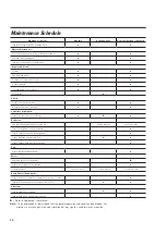
Page 26: ...ion every 3 mo every 3 months every 3 months Check and tighten support fasteners x Check shaft sheave and belt alignment x Check belt tension and condition x x Check sheave bushing fastener torque x F...

Page 27: ...ments contain important information relating to safe installation and operation of the fluid cooler Field installation is required for some optional accessories A separate installation drawing or manu...

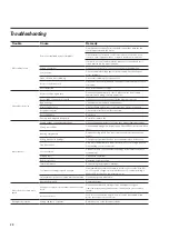
Page 28: ...nstall or replace fan Motor runs hot Wrong voltage or unbalanced voltage Check voltage and current of all three lines against nameplate values Wrong motor RPM Check nameplate against power supply Chec...

Page 29: ...e is above design Check to see if local heat sources are affecting fluid cooler See if surrounding structures are causing recirculation of tower discharge air Discuss remedy with Marley representative...

Page 30: ......

Page 31: ......
Page 32: ...3 8AB UNITED KINGDOM 44 0 1905 720 200 info uk spx com spxcooling com In the interest of technological progress all products are subject to design and or material change without notice 2008 SPX Coolin...

Reviews: