background image

42

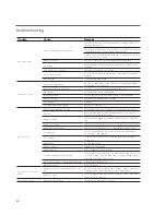
troubleshooting

Trouble

Cause

Remedy

Motor will not start

Power not available at motor terminals

Check power at starter. Correct any bad connections between the control 
apparatus and the motor.

Check starter contacts and control circuit. Reset overloads, close contacts, 
reset tripped switches or replace failed control switches.

If power is not on all leads at starter, make sure overload and short circuit 
devices are in proper condition

Wrong connections

Check motor and control connections against wiring diagrams.

Low voltage

Check nameplate voltage against power supply. Check voltage at motor 
terminals.

Open circuit in motor winding

Check stator windings for open circuits.

Motor or fan drive stuck

Disconnect motor from load and check motor and fan drive for cause of 
problem.

Rotor defective

Look for broken bars or rings.

Unusual motor noise

Motor running single-phase

Check motor and attempt to start it. Motor will not start if single-phased. 
Check wiring, controls and motor.

Motor leads connected incorrectly

Check motor connections against wiring diagram on motor.

Bad bearings

Check lubrication. Replace bad bearings.

Electrical unbalance

Check voltages and currents of all three lines. Correct if required.

Air gap not uniform

Check and correct bracket fits or bearing.

Rotor unbalance

Rebalance

Cooling fan hitting end belt guard

Reinstall or replace fan.

Motor runs hot

Wrong voltage or unbalanced voltage

Check voltage and current of all three lines against nameplate values.

Overload

Check fan blade pitch. See “Fan User Manual.” Check for drag in fan 
drivetrain as from damaged bearings.

Wrong motor RPM

Check nameplate against power supply. Check RPM of motor and drive 
ratio.

Bearing over greased

Remove bearing reliefs. Run motor up to speed to purge excessive grease.

Wrong lubricant in bearings

Change to proper lubricant. See motor manufacturer's instructions.

One phase open

Stop motor and attempt to start it. Motor will not stat if single-phased. 
Check wiring, controls and motor.

Poor ventilation

Clean motor and check ventilation openings. Allow ample ventilation 
around motor.

Winding fault

Check with ohmmeter.

Bent motor shaft

Straighten or replace shaft.

Insufficient grease

Remove plugs and regrease bearings.

Too frequent starting or speed changes

Limit cumulative accelerations time to a total of 30 seconds/hour. Set on/
off or speed change set points farther apart. Consider installing a Marley 
VFD drive for fine temperature control.

Deterioration of grease or foreign material in grease

Flush bearings and relubricate.

Bearings damaged

Replace bearings.

Motor does not come up to 
speed

Voltage too low at motor terminals because of line 
drop

Check transformer and setting of taps. Use higher voltage on transformer 
terminals or reduce loads. Increase wire size or reduce inertia.

Broken rotor bars

Look for cracks near the rings. A new rotor may be required. Have motor 
service person check motor.

Wrong motor rotation

Wrong sequence of phases

Switch any two of the three motor leads.

Summary of Contents for MH Fluid Cooler

Page 1: ...MH Fluid Cooler I N STALLATION OPE RATION MAI NTE NANCE uk_Z0876176 rev A I SSU E D 10 2014 READ AND UNDERSTAND THIS MANUAL PRIOR TO OPERATING OR SERVICING THIS PRODUCT US E R MAN UAL...

Page 2: ...tal information for the proper installation and operation of your fluid cooler Carefully read the manual before installation or operation of the fluid cooler and follow all instruc tions Save this man...

Page 3: ...ccess door Safety First The location and orientation of the fluid cooler can affect the safety of those responsible for installing operating or maintaining the fluid cooler However since SPX Cooling T...

Page 4: ...MHF7111 and MHF7113 only Ladder extensions used where the base of the fluid cooler is elevated Safety cages for ladders External lube lines Access door platform Motor located outside the fluid cooler...

Page 5: ...ding the fluid cooler from the delivering carrier inspect the ship ment for evidence of damage in transit If damage is apparent note the freight bill accordingly This will support your future recovery...

Page 6: ...ooler will govern 1 Prior to placement of the fluid cooler confirm that the supporting platform is level and that the anchor bolt holes are correctly located in accordance withMarleydrawings Ifyourins...

Page 7: ...rge point make those connections at this time also Fasteners and components provided by others that are to be at tached to the fluid cooler must be compatible with the fluid cooler materials i e faste...

Page 8: ...e wired to main power supply through short circuit protection and a magnetic starter with overload protection Motor Wiring Wire motor leads as shown on the motor nameplate matching the supply voltage...

Page 9: ...mended to avoid damage to the motor 100 feet distance is based on our field experience the VFD manufacture may state different distances and distance does vary depending on the VFD manufacturer Progra...

Page 10: ...ed and half speed Warrantyisvoidifthefluidcoolerisoperatedatspeedswhichcause damaging vibrations to the fluid cooler and associated equipment When utilizing a variable frequency drive the fluid cooler...

Page 11: ...eads supplying power to the motor Iffluidcoolerisequippedwithatwo speedmotor checkforproperro tationatbothspeeds Checkalsotoseethatstarterisequippedwitha 20 second time delay which prevents direct swi...

Page 12: ...ke sure that cold water suction screens are clear and properly installed 3 Fill the water system to an approximate depth of 8 in the depressed area of the collection water basin This is the recommende...

Page 13: ...um recommended biocide residual for the specific biocide for a sufficient period of time residual and time will vary with the biocide to bring the system under good biological control or Treat the sys...

Page 14: ...ver the cold process fluid temperature will not vary linearly with the wet bulb For example a 11 C reduction in wet bulb may result in only a 8 C reduction in cold process fluid temperature 3 Fluid fl...

Page 15: ...wer Energy Management available at spxcooling com Pump cycling limits Cycling the recirculating water pump s to control processfluidtemperatureisnottypicallyrecommended Itisrecommended that while proc...

Page 16: ...environment until installed If a unit is going to sit idle prior to startup the actua tor must be removed from the damper and stored appropriately Dry Operation AlsorefertotheFreezingWeatherOperation...

Page 17: ...id temperature to drop below 7 C If such low temperature operation is necessary or beneficial to your process establish the minimum allowable level as follows During the coldest days of the first wint...

Page 18: ...ll eventually strike this ring of ice damaging the fan blades or cylinder Ice can also accumulate on fan blades and be thrown off damaging fan cylinder or blades Allow a minimum of 10 minute delay bet...

Page 19: ...ocess fluid Fluid exiting the coil must be maintained at or above 7 C Cycling of the recirculation pump should not be used to control process temperatures operation Model Wet Coil m3 Dry Coil m3 Model...

Page 20: ...h unusual chemicals or foreign substances and adequate water treatment to minimize scaling Startup Conditions The water conditions during initial fluid cooler opera tion are crucial in preventing prem...

Page 21: ...tant discharge of a portion of the circulating water to waste As a rule acceptable levels on which to base a treatment schedule will be in the range of 2 4 concentrations The following table shows the...

Page 22: ...ublic Health Service officials have recommended that good housekeeping procedures be followed such as regular inspections for concentrations of dirt scale and algae periodic flushing and cleaning and...

Page 23: ...tion To ensure packs are reinstalled in the correct orientation it is recommended that one pack is left in its original location inside the fluid cooler as a reminder of pack orientation Replace packs...

Page 24: ...Repeat this procedure for other packs to gain necessary access Proper eliminator pack replacement is essential to operation Incorrect installation may result in excessive drift rates and fan inefficie...

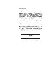
Page 25: ...ired to support the motor Tighten the hardware after adjustment Ideal tension is the lowest tension at which the belt will not slip under peak load conditions Check tension frequently during the first...

Page 26: ...acking screws Do not remove the hardware it is required to support the motor Tighten the hardware after adjustment Ideal tension is the lowest tension at which the belt will not slip under peak load c...

Page 27: ...s Do not remove the hardware Next loosen the four motor plate to side gusset bolts Do not remove the hardware It may help to grease three radial motor slots before turning the adjustment bolts If one...

Page 28: ...elt and bearing life Keep belts free from foreign material which may cause slipping Never apply belt dressing as this will damage the belt and cause early failure A Dodge V Belt Tension Tester is an a...

Page 29: ...ak load conditions Check tension frequently during the first 24 48 hours of run in operation Over tensioning shortens belt and bearing life Keep belts free from foreign material which may cause slippi...

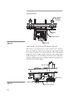
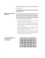
Page 30: ...urface of the motor and fan sheaves must be aligned within 3mm of each other and level within 1 2 3mm in 30cm in order to not adversely affect belt and sheave life Alignment can be achieved by placing...

Page 31: ...POINTS OF CONTACT WHEN A STRAIGHT EDGE IS LAID AROSS THE TOP OF BOTH SHEAVES ALIGN THE BOTTOM EDGES OF THE FAN AND MOTOR SHEAVES WHILE ENSURING THAT BOTH ARE FULLY ENGAGED ON THEIR SHAFTS THERE SHOUL...

Page 32: ...als will take precedence Thefollowingisrecommendedasaminimumroutineofscheduledmaintenance Always shut off electrical power to the fluid cooler fan motor prior to performing any inspections that may in...

Page 33: ...will enable you to determine the rate at which it is forming If equipped with dampers lubricate the pivot points of the individual blades Observe the area where the steel pivot pins penetrate the asse...

Page 34: ...ther instructions Annually Relubricate motor s according to the manufacturer s instructions See instructions on the next page for fluid coolers with the motor located outside the plenum option Check t...

Page 35: ...relief plugs at both shaft extension end and opposite end bearings and remove hardened grease using clean wire 3 Insert grease fittings in grease fill openings and add grease until grease is forced o...

Page 36: ...ight metal can be exposed by cleaning consider that the galvanizing has remained effective Unless there is evidence of a generalized failure of the galvanizing localized touch up should be all that is...

Page 37: ...endation attached General Protective Requirements for Fluid Coolers The fan opening at the top of the fluid cooler should be covered with a tarp This will protect the mechanical components from rain a...

Page 38: ...stress free which is to say without tension pressure or other causes of deformation as strain causes permanent deformation and failure due to fatigue as well as cracking If for reasons of space they a...

Page 39: ...interest in your MH Fluid Cooler does not end with the sale Having con ceived designed and manufactured the most reliable and longest lasting fluid cooler of its class we want to make sure that you g...

Page 40: ...t of rebuilding before you routinely order a new replacement fluid cooler Each MH Fluid Cooler includes a document package containing general orientation drawings and fluid cooler component manuals Th...

Page 41: ...x x Lube lines if equipped Check for oil leaks in hoses or fittings x R x Belt drive if equipped Fan shaft bearing lubrication every 3 mo every 3 months every 3 months Check and tighten support fasten...

Page 42: ...nbalanced voltage Check voltage and current of all three lines against nameplate values Overload Check fan blade pitch See Fan User Manual Check for drag in fan drivetrain as from damaged bearings Wro...

Page 43: ...Grease bearings Scale or foreign substance in circulating water system Insufficient blowdown See Water Treatment section of this manual Water treatment deficiency Consult competent water treating spe...

Page 44: ...BRIDGE PARK WAINWRIGHT ROAD WORCESTR WR4 9FA UK P 44 1905 750 270 F 913 664 7439 info uk spx com In the interest of technological progress all products are subject to design and or material change wit...

Reviews: