background image

ABS / Air Bag 2004 User Guide

Safety Precautions

Safety Precautions

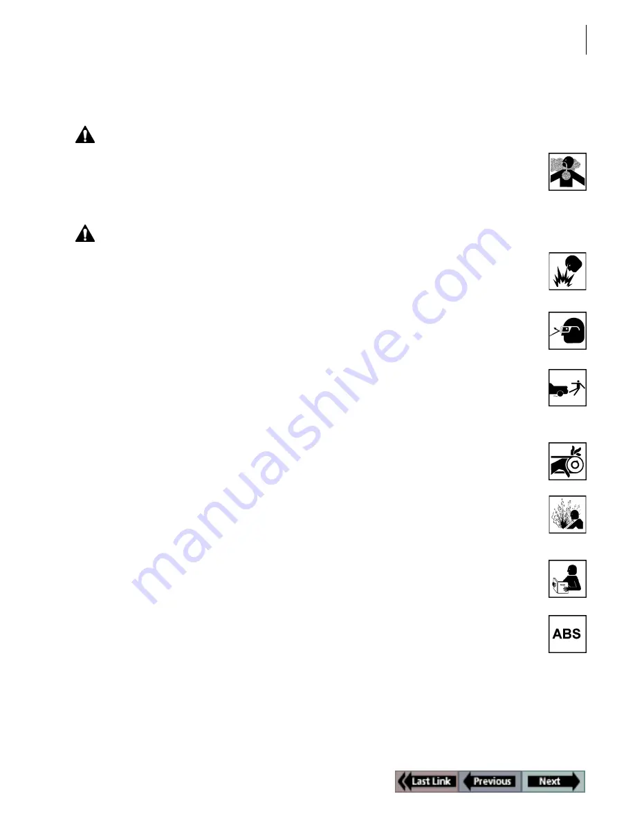
Danger:

• When an engine is operating, keep the service area WELL VENTILATED or attach a building 

exhaust removal system to the engine exhaust system. Engines produce carbon monoxide, 
an odorless, poisonous gas that causes slower reaction time and can lead to serious injury 
or death.

Warning:

• When working with hydraulic or fuel lines, liquids under pressure may escape and create a 

dangerous condition. Never open a bleeder valve or loosen a hydraulic line while the ABS 
is pressurized. Use adequate ventilation and make sure there are no sparks or possibility of 
sparks present that may ignite any vapor.

• Wear an American National Standards Institute (ANSI) approved eye shield when testing or 

repairing vehicles. Objects propelled by whirling engine components or pressurized liquids 
escaping may cause personal injury.

• Set the parking brake and block the wheels before testing or repairing a vehicle. It is especially

important to block the wheels on front-wheel drive vehicles because the parking brake does 
not hold the drive wheels.

• Do not drive the vehicle and operate the NGIS tool at the same time. Any distractions may 

cause an accident. Have one person operate the NGIS tool as another person drives the vehicle.

• Maintain adequate clearance around moving components or belts during testing. Moving

components and belts can catch loose clothing, body parts, or test equipment and cause 
serious damage or personal injury.

• Automotive batteries contain sulfuric acid and produce explosive gases that can result in 

serious injury. To prevent ignition of gases, keep lighted cigarettes, sparks, flames, and other 
ignition sources away from the battery at all times. If you are using the battery as a power 
source, connect the RED (+) battery clip to the positive vehicle battery terminal and connect 
the BLACK (-) battery clip to a good ground away from the battery.

• Refer to the service manual for the vehicle being serviced and adhere to all diagnostic

procedures and precautions. Failure to do so could result in air bag deployment, personal
injury, or otherwise unneeded air bag system repairs.

• Only use specially designed replacement parts (brake hoses and lines) for ABS-equipped 

vehicles.

• After bleeding the brake system, check the brake pedal for excessive travel or a “spongy” 

feel. Bleed again if either condition is present.

• When installing transmitting devices (Citizen Band radio, telephone, etc.) on ABS-equipped 

vehicles, do not locate the antenna near the ABS control unit or any other control unit.

Summary of Contents for ABS / AIR BAG 2004

Page 1: ...ABS AIR BAG 2004 USER GUIDE...

Page 2: ...jeopardize your personal safety COPYRIGHT No part of this manual may be reproduced stored in a retrieval system or transmitted in any form or by any means electronic mechanical photocopying recording...

Page 3: ...ABS AIR BAG 2004 SOFTWARE for the NEXT GENERATION INFORMATION SYSTEM TOOL USER GUIDE...

Page 4: ......

Page 5: ...9 5 Battery Adapter 212638 5 Software Description 6 Software Installation 6 Software Screens 6 Application Manager Screen 6 Vehicle Identification Screen 7 Vehicle Identification Required Cables Scree...

Page 6: ...Frame 25 Pathfinder 25 Print 26 Zoom 26 Sort 27 English Metric Units 28 Show Hide LED Bar 29 Show Hide Analog 30 Chapter 4 Custom Datastream 31 Chapter 5 Diagnostic Codes Read Clear Codes 33 Read Code...

Page 7: ...lic Control Tests 63 Idle Up Manual Control Test 63 Lamp Tests 63 Manual Control Test 63 Motor Rehome Test 64 Pump Motor Tests 64 Relay Test 64 Requested Torque Test 64 Setup SDM Serial Number Air Bag...

Page 8: ...This page is intentionally blank...

Page 9: ...ractions may cause an accident Have one person operate the NGIS tool as another person drives the vehicle Maintain adequate clearance around moving components or belts during testing Moving components...

Page 10: ...wheel speed readings Do not expose the ABS control unit to prolonged periods of high heat 185 degrees F 85 degrees C for 2 hours is considered a maximum limit Use a recommended brake fluid do not use...

Page 11: ...sed vehicle setup for you to reuse quickly You can also save vehicle setups for reuse You can view live sensor and switch datastream infor mation while it is being communicated from the vehicle s ECU...

Page 12: ...he User Guide for the NGIS tool As a quick reference the NGIS keys are listed below Function keys four of them each key executes a com mand that corresponds with an option listed at the bottom of the...

Page 13: ...pin Male Connector connects to the DB25 port on the top of the NGIS tool The 25 pin connector has a port on the top of it for inserting a System Smart Insert SSI DB25 Power Cable 3305 72 Figure 1 4 D...

Page 14: ...ata link connector DLC of the vehicle s electronic control unit Item 3 Special Leads not shown special add on leads 216094 and 3305 69 may be required for some vehicles Universal C Adapter 3305 74 Fig...

Page 15: ...equipped with Sumitomo anti lock brake systems The adapter has the following components Item 1 DLC Connector connects to the data link connector DLC of the vehicle s electronic control unit Item 2 8 P...

Page 16: ...software Some of the screens contain menus and others contain test instruc tions or results Application Manager Screen When you turn on the NGIS tool the Application Manager screen appears The Applica...

Page 17: ...n changes to options for selecting the vehicle s year range After you have entered all the information for a vehicle the middle section displaysthe cable connections required for the vehicle shown on...

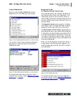
Page 18: ...n reality only the options available for the vehicle being tested will appear on this menu Datastream When you select Datastream from the Diagnostic menu the following screen appears Figure 1 17 Datas...

Page 19: ...ion is Diagnostic Codes for other vehicles there are two menu options Read Codes and Clear Codes as described below The Diagnostic Codes option appears on the Diag nostic Menu screen for vehicles that...

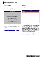
Page 20: ...6 Post Collision Test on page 45 Pathfinder When you select Pathfinder from the Diagnostic menu the following screen appears Figure 1 22 Pathfinder Screen The Pathfinder screen contains menu options...

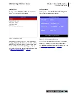
Page 21: ...ecifications technical service bulletin TSB refer ences and the vehicle description system type For detailed information about using this screen refer to Chapter 8 Vehicle Info on page 55 Controller I...

Page 22: ...dow contains a Table of Contents You click a topic to display its contents The right side of the window displays the contents you can right click inside the contents to display a navigation menu You c...

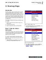
Page 23: ...quired 2 Connect the required cable 3 Select the diagnostic function you want to perform Step 1 Enter the Vehicle Information Use the following steps to enter vehicle information and to determine whic...

Page 24: ...Jetta Bora Beetle or a similar SEAT or Skoda model physically inspect the air bag controller and look at the part number If it is not 6Q0 909 605 A then it should be safe to test If it is Q0 909 605 A...

Page 25: ...on key This places a disk icon to the left of the file name and saves the description until you delete it Use the Delete function key to delete a selected description 7 After you have entered new vehi...

Page 26: ...generally requires the System Smart 25 pin cable 3305 73 and a System Smart Insert SSI Note For a description of the cables refer to Cables on page 3 To connect the System Smart 25 pin cable follow th...

Page 27: ...DB25 port on the top of the NGIS tool Finger tighten the connecting screws see Figure 2 11 Note Extension cable 3305 71 can be used between the NGIS tool and the DB25 Power cable Refer to Extension C...

Page 28: ...sting only the options available for the vehicle being tested will appear on this screen 3 Select the option for the diagnostic function you want to perform and press the ENTER key 4 For specific step...

Page 29: ...adings Automatic Diagnostic Code Triggered Record The ABS Air Bag 2004 software has an automatic Diag nostic Code Triggered Record function This function works automatically and does not appear as an...

Page 30: ...t few pages include the following Record and Playback records the data for viewing again at a later time See page 21 Graph Analog LED Digital depending on the type of data on a line changes the view o...

Page 31: ...file follow these steps 1 Press the MENU key to display the Application Manager screen 2 From the Application Manager screen select Playback This displays the Events to Playback screen Note The Events...

Page 32: ...s the next display type that will appear when you press the key 3 Repeat steps 1 and 2 for each line to change About Digital Display When a line is displayed as Digital its reading is a word or a numb...

Page 33: ...maximum mea surements appear to the right of the graph and the digital reading is below the graph You can use the Left and Right Direction keys to move the magnified window through the data See Freeze...

Page 34: ...es remain locked for the selected vehicle until you unlock them even if you exit the software 4 To unlock a locked line select the locked line and then press the ENTER key see steps 1 and 2 To Top The...

Page 35: ...for each frame 3 Use the Left or Right Direction keys to move backward or forward through the data frame by frame 4 When finished press the EXIT key to return to the normal screen display and to resum...

Page 36: ...OK function key Zoom The Zoom function on the Datastream screen s More menu lets you magnify the view of each data line on the Datastream screen Note This function applies to digital graph and LED dis...

Page 37: ...ally or with either locked or graphed lines at the top of the screen Note You can also use the To Top function to rearrange the data lines For details refer to To Top on page 24 To sort the data lines...

Page 38: ...Alphabet Function English Metric Units The English Metric Units function on the Datastream screen s More menu lets you change the units of mea sure for the data from English to Metric or vice versa To...

Page 39: ...en displayed press the MORE function key 2 Use the Down Direction key to select the Show LED Bar or HIde LED Bar function Note This name of this menu option changes each time you select it It changes...

Page 40: ...aph Analog LED Digital on page 22 To hide or show the analog gauges follow these steps Figure 3 24 Datastream Screen Show Hide Analog Function 1 With the Datastream screen displayed press the MORE fun...

Page 41: ...ections 2 Select the data items to include in the Datastream display as follows a Use the Up and Down Direction key to select an item to include in the display b Press the ENTER key A check mark appea...

Page 42: ...32 This page is intentionally blank...

Page 43: ...stic Menu screen instead of the Diagnostic Codes option for vehicles that require reading of DTCs by visually viewing them as flash codes For this type of vehicle you identify the vehicle s flash code...

Page 44: ...ding and displaying of codes in one procedure Note For vehicles that require reading of DTCs by visually viewing them as flash codes refer to Read Codes Clear Codes Flash Codes on page 42 To read and...

Page 45: ...e 26 Note For some vehicles the DTC Info screen has a Pathfinder function key This function key lets you access the Pathfinder software s Quick Path function from with in the ABS Air Bag software For...

Page 46: ...this until the test screen appears see Figure 5 10 Figure 5 10 Read Codes Test Screen 4 The test screen displays the codes being read and the time remaining for the test When the test is finished the...

Page 47: ...ss the ENTER key This displays the list of codes on the Review Codes screen Note If there are no codes to display a message screen states that the code library is empty If necessary read the codes Ref...

Page 48: ...manufacturer s service manual for the correct clear code method To clear the diagnostic trouble codes follow these steps Note Before performing this procedure make sure the vehicle s ignition key is i...

Page 49: ...lem may still exist in the vehicle Note GM supplemental inflatable restraint SIR code 52 which indicates the air bag has been deployed cannot be cleared All other codes clear and the SIR dash warning...

Page 50: ...on the screen and press the OK function key 6 One or more instruction screens may appear If so read each screen and use the function keys to answer any questions Do this until the list of codes appea...

Page 51: ...ions Do this until the Wiggle Test screen appears Figure 5 27 Wiggle Test Screen 4 The test screen displays the state of the test the number of transitions circuit breaks that occur and the time remai...

Page 52: ...or to trigger a specific indictor light to blink and 2 viewing and counting the number of times the indicator light blinks This section includes the following procedures Read Codes Flash Codes in the...

Page 53: ...Possible Codes Screen 6 Use the Possible Codes screen to enter the flash codes as follows a Use the Direction keys to select highlight a code number With the number selected press the ENTER key b Repe...

Page 54: ...ual for the correct clear code method To clear flash codes follow these steps Figure 5 34 Diagnostic Menu Screen 1 From the Diagnostic Menu screen select Clear Codes and press the ENTER key This displ...

Page 55: ...Diagnostic Trouble Codes menu screen 1 Select Post Collision Test and press the ENTER key This displays an instruction screen Figure 6 2 Post Collision Test Screen 2 Read the screen follow the instru...

Page 56: ...ew the list and save or print it if necessary To view a saved file refer to Playback a Data File on page 21 For printing information refer to Print on page 26 Note For more information about DTCs and...

Page 57: ...Specifications used to view brake and ABS specifica tions for a vehicle See page 51 Component Location used to view a description of the computer and connector locations for a vehicle See page 52 Brak...

Page 58: ...lets you access the Fast Fixes software from within the ABS Air Bag software The Fast Fixes software contains vehicle specific repair solutions for many likely or overlooked causes of component proble...

Page 59: ...a symptom cause to view and press the ENTER key This displays the Fast Fix Select Component screen Figure 7 7 Fast Fix Select Component Screen 5 From the list of components select a component to view...

Page 60: ...der and press the ENTER key This displays the Pathfinder screen 2 From the Pathfinder screen select TSB References and press the ENTER key This displays the TSB References screen Figure 7 10 TSB Refer...

Page 61: ...agnostic Menu Screen and Pathfinder Screen 1 From the Diagnostic Menu screen select Pathfinder and press the ENTER key This displays the Pathfinder screen 2 Select Specifications and press the ENTER k...

Page 62: ...on and press the ENTER key to view a description of where the vehicle s data link connector DLC is located This displays the Con nector Location screen see Figure 7 15 Select Computer Location and pre...

Page 63: ...ENTER key This displays the Pathfinder screen 2 Select Brake Bleed Procedure and press the ENTER key This displays the Brake Bleed Procedure screen 3 Select either Manual Bleed or Pressure Bleed and...

Page 64: ...gnostic Menu Screen and Pathfinder Screen 1 From the Diagnostic Menu screen select Pathfinder and press the ENTER key This displays the Pathfinder screen 2 Select Brake Bleed Sequence and press the EN...

Page 65: ...used to view PROM information See page 58 Note Before performing the procedures in this chapter fol low the instructions in Chapter 2 Start up Steps on page 13 Specifications The Specifications option...

Page 66: ...elect Vehicle Info and press the ENTER key This displays the Vehicle Info screen 2 Select Related TSBs and press the ENTER key This dis plays the TSB References screen Figure 8 4 TSB References Screen...

Page 67: ...hicle Info Screen 1 From the Diagnostic Menu screen select Vehicle Info and press the ENTER key This displays the Vehicle Info screen 2 Select System Type and press the ENTER key This displays the Sys...

Page 68: ...w PROM information follow these steps Figure 8 8 Diagnostic Menu Screen and Vehicle Info Screen 1 From the Diagnostic Menu screen select Vehicle Info and press the ENTER key This displays the Vehicle...

Page 69: ...forming the test steps follow the instruc tions in Chapter 2 Start up Steps on page 13 To display the Controller ID information follow these steps Figure 9 1 Diagnostic Menu Screen 1 Select Controller...

Page 70: ...60 This page is intentionally blank...

Page 71: ...you with a screen message and creates a recording for playback To replay these recordings refer to Playback a Data File on page 21 WARNING Before performing any tests refer to the Safety Pre cautions...

Page 72: ...vehicle being tested ABS Manual Control Tests Manual Control Tests let you use the NGIS tool to man ually control the actuators in order to test the following ABS motors solenoids solenoid enable rela...

Page 73: ...or on and off to test for proper operation If there is a malfunction a diag nostic trouble code DTC is set in the vehicle Brake Bleed Preparation Test The Brake Bleed Preparation Test prepares the bra...

Page 74: ...Test lets you use the NGIS tool to manually control the engine torque to test for proper operation of the traction control system TCS Setup SDM Serial Number Air Bag Sensing and Diagnostic Module The...

Page 75: ...components Basic Single Component Control Screen The following screen is the basic manual control screen for a single component You press the Start function key to begin and then use the On and Off fu...

Page 76: ...NGIS tool to the state of the component being read by the ECU to the actual physical state of the component Item 5 The More menu contains basic Datastream functions For details refer to Datastream Fu...

Page 77: ...ions Item 4 The status line displays the current status of the test Item 5 The Start function key starts the test Activate Deactivate Screen The following screen is an example of a manual control scre...

Page 78: ...68 This page is intentionally blank...

Page 79: ...ITY OR FITNESS FOR A PARTICULAR PURPOSE SOFTWARE Unit software is proprietary confidential information protected under copyright law Users have no right in or title to Unit software other than a limit...

Page 80: ...2005 SPX Corporation All rights reserved 06 14 05 Part Number 531371...

Reviews: