3
2.0 Description
2.1 Function
Dual tower regenerative desiccant dryers are utilized to dry
compressed air to dew points below the freezing point of
water or reduce the moisture content to low levels for use in
critical process applications.
Air is dried by using two identical towers, each containing a
desiccant bed. While one tower is on-stream drying the com-
pressed air, the other tower is off-stream being regenerated
(reactivated, i.e., dried out).
Desiccant dryers lower the dew point by adsorbing most of
the water vapor present onto the surface of the desiccant.
Adsorption occurs until an equilibrium is reached between
the partial pressure of the water vapor in the air and that on
the surface of the desiccant.
Desiccant can then be regenerated by desorbing the water
collected on its surface. Regeneration occurs by expanding
a portion of the dried air to atmospheric pressure. This very
dry air (called purge air) causes the moisture to desorb from
the desiccant and then carries the desorbed water out of the
dryer.
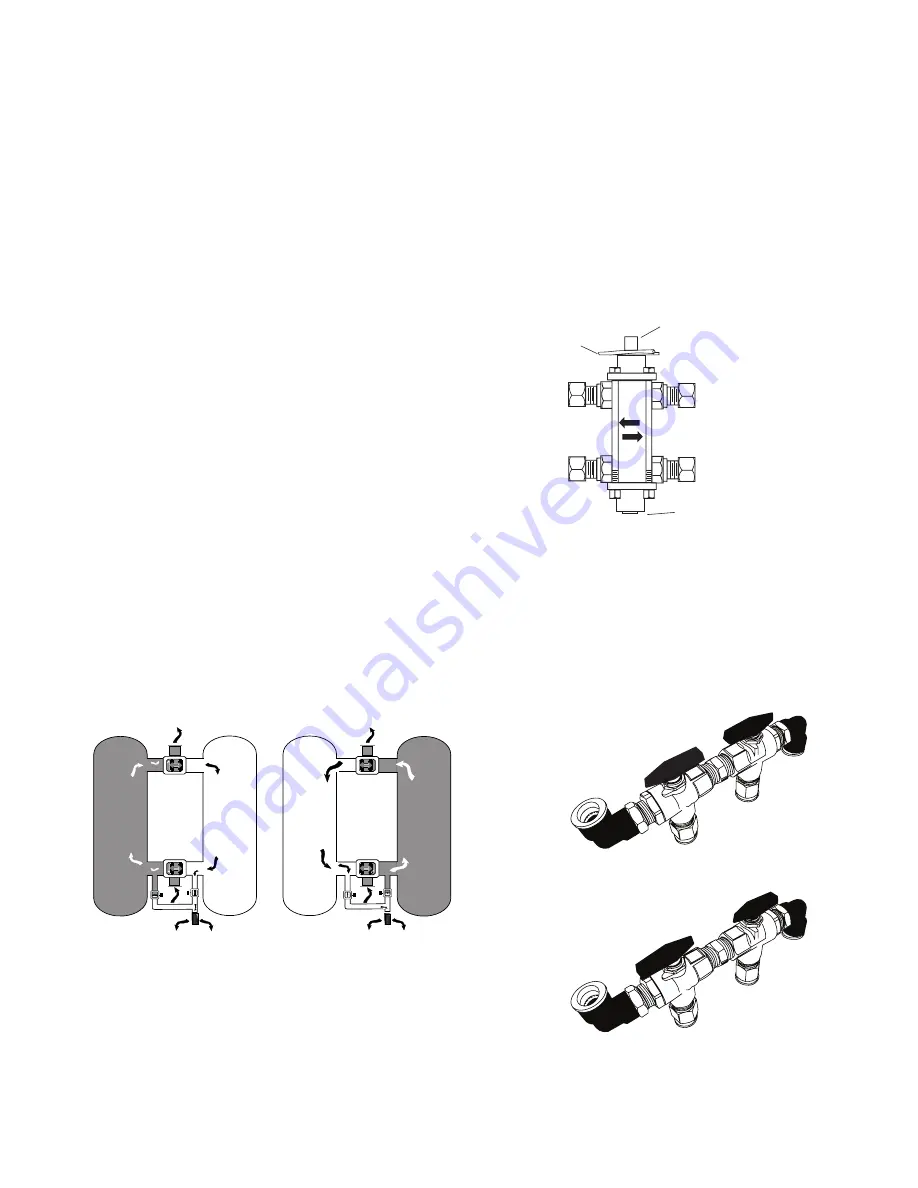
2.2 Operation
Compressed air enters the dryer and is directed to TOWER 1
through valve (A) and then exits the dryer through shuttle
valve (B). A portion of the dried air is throttled to near atmo-
spheric pressure by means of an orifice (C). This extremely
dry, low pressure air flows through and regenerates the
desiccant in TOWER 2 and is then exhausted through purge/
repressurization valve (D) and exhaust muffler (E) to atmo-
sphere.
After a set time, the automatic solid state timer closes
purge/repressurization valve (D) allowing TOWER 2 to repres-
surize slowly.
At the end of 2 minutes, valve (F) opens and Tower 1 depres-
surizes. The main air flow is now dried by TOWER 2 while
TOWER 1 is regenerated.
TOWER
1
TOWER
2
E
D
F
C
B
A
TOWER
1
TOWER
2
A
F
D
E
B
C
Figure 1 – Flow Schematic
Models 7 through 50
2.3 Air By-Pass Assembly
An optional air by-pass assembly is available for all models.
When ordered with the dryer, the by-pass assembly is factory
installed inside the dryer cabinet. Make sure the by-pass
assembly is in the desired mode: "Dry" (compressed air flow
through the dryer) or "By-pass" (compressed air by-passes
the dryer).
2.3.1 Models 7 and 13
The by-pass assembly includes a by-pass valve with a manu-
ally operated spool. One end of the spool is marked "Push
to Dry" and the other end is marked "Push to Bypass". To
select the desired mode, remove the locking pin, push and
fully depress the appropriately marked end of the spool, and
install the locking pin in the opposite end.
IN
OUT
Push to by-pass dryer
Locking Pin
Push to Dry
Models 7 and 13
Optional by-pass
Figure 2a – Air Bypass Assembly
Models 7 and 13
2.3.2 Models 20, 25, 30, 35, and 50
The by-pass assembly includes two manually operated three-
way valves. To select "Dry" mode, rotate the valve handles
so that the arrows point away from each other. To select
"By-Pass" mode, rotate the valve handles so that the arrows
point toward each other.
Dry Mode
By-Pass Mode
Figure 2b – Air Bypass Assembly
Models 20 through 50


