background image

4

3.0 Installation

3.1  Dimensions, Connections, Weight

Maximum Operating Pressure:  


150 psig, 10.5 kgf/cm

2

Maximum Operating Temperature:  


120°F, 49°C

MODEL

NUMBER

DIMENSIONS   in (mm)

CONNECTIONS

WEIGHT

lb (kg)

A

B

C

D

E

F

H

J

K

M

INLET

OUTLET

7

13
20
25
30
35
50

31.09 (790)
31.09 (790)
31.09 (790)
37.94 (964)
37.94 (964)
37.94 (964)
37.94 (964)

17.52 (445)
17.52 (445)
17.52 (445)
24.37 (619)
24.37 (619)
24.37 (619)
24.37 (619)

1.15 (29)
1.15 (29)
1.15 (29)
1.68 (43)
1.68 (43)
1.68 (43)
1.68 (43)

15.23 (387)
15.23 (387)
15.23 (387)

21 (533)
21 (533)
21 (533)
21 (533)

6.69 (170)
6.69 (170)
6.69 (170)
8.54 (217)
8.54 (217)
8.54 (217)
8.54 (217)

3.74 (95)
3.74 (95)
3.74 (95)

6.73 (171)
6.73 (171)
6.73 (171)
6.73 (171)

30.5 (775)
30.5 (775)
30.5 (775)
31.6 (803)
31.6 (803)
31.6 (803)

43.3 (1100)

3.74 (95)
3.74 (95)
3.74 (95)

4.25 (108)
4.25 (108)
4.25 (108)
4.25 (108)

5.31 (135)
5.31 (135)
5.31 (135)
6.22 (158)
6.22 (158)
6.22 (158)
6.22 (158)

27.5 (699)
27.5 (699)
27.5 (699)
27.5 (699)
27.5 (699)
27.5 (699)
39.3 (998)

1/2" NPT (F)
1/2" NPT (F)
1/2" NPT (F)
1/2" NPT (F)
1/2" NPT (F)
1/2" NPT (F)
1/2" NPT (F)

1/2" NPT (F)
1/2" NPT (F)
1/2" NPT (F)
1/2" NPT (F)
1/2" NPT (F)
1/2" NPT (F)
1/2" NPT (F)

55 (25)
60 (27)
71 (32)
93 (42)
93 (42)
99 (45)

132 (60)

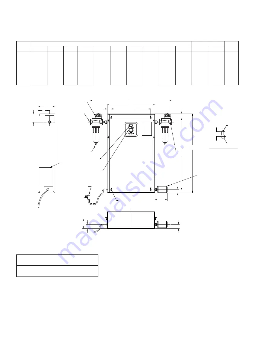
SEE MOUNTING 

SLOT DETAIL 

6' POWER CORD 

(SEE NOTE 1) 

ELECTRICAL ENTRY

ON/OFF

SWITCH

TOWER

INDICATING

LIGHTS

BACK OF ENCLOSURE

MOUNTING SLOT DETAIL

PURGE 

MUFFLER

1/4" R.

5/8"

1.69

(43)

1/8" R.

FIELD MOUNTED

PREFILTER 

INLET

FIELD MOUNTED

AFTERFILTER 

OUTLET

AIR INLET 

H

M

E

F

2.46

(62.5)

INSTRUCTION

TAG

C

D

B

A

SERIAL

NO.

TAG

(INSIDE
COVER)

F

J

2.36

(60)

K

2.36

(60)

AUTOMATIC DRAIN

DIFFERENTIAL PRESSURE

INDICATOR

P1 

P2 

Figure 3 Dimensional Drawing 

NOTE:  

1.  Dimension "A" applies only to units equipped 

with optional prefilter and afterfilter package.  

Specific dimensions of filters available upon 

request.

2.  Connection sizes valid with or without filters.

3.  Weight applies to unit only, add 6-1/2 lbs. 

(3 kg) to weight for optional filter package 

when specified.

Summary of Contents for Hankison DHW 13

Page 1: ...Swing Desiccant Compressed Air Dryer Models 7 through 50 scfm FOR M NO 3215738 R EVI S ION 07 2014 R EAD AN D U N D E R STAN D TH I S MAN UAL PR IOR TO OPE RATI NG OR S E RVICI NG TH I S PROD UCT I N...

Page 2: ...cking notify the carrier immediately and insist on his agent inspecting the shipment Fifteen days from receipt of shipment is the maximum time limit for requesting such inspection Concealed damage cla...

Page 3: ...ssurization valve D and exhaust muffler E to atmo sphere After a set time the automatic solid state timer closes purge repressurization valve D allowing TOWER 2 to repres surize slowly At the end of 2...

Page 4: ...8 6 22 158 6 22 158 27 5 699 27 5 699 27 5 699 27 5 699 27 5 699 27 5 699 39 3 998 1 2 NPT F 1 2 NPT F 1 2 NPT F 1 2 NPT F 1 2 NPT F 1 2 NPT F 1 2 NPT F 1 2 NPT F 1 2 NPT F 1 2 NPT F 1 2 NPT F 1 2 NPT...

Page 5: ...o at least 120 F 49 C Use aftercooler and separator if higher temperatures are present A 1 2 1 2 C DESICCANT DRYER COMPRESSOR AFTERCOOLER SEPARATOR A B D PREFILTERS AFTERFILTERS NOTE Installation of a...

Page 6: ...pressure gauge to ensure proper flow direction through filter 3 5 Wall mounting Four holes are provided in rear of cabinet Attach cabinet to wall using four 4 screws User is responsible for select in...

Page 7: ...for various inlet pressures INLET PRESSURE psig 50 60 70 80 90 100 110 120 130 140 150 kgf cm2 3 5 4 2 4 9 5 6 6 3 7 0 7 7 8 4 9 1 9 8 10 5 Multiplier 0 31 0 42 0 54 0 73 0 83 1 00 1 09 1 17 1 26 1 3...

Page 8: ...by multiplying Average Purge Flow at 100 psig from Table 1 by Purge Flow Correction Factor from Table 4 2 7 x 1 17 3 2 scfm the average purge flow Step 4 Find Minimum Outlet Flow available by subtrac...

Page 9: ...eep containers closed until use to avoid mois ture contamination If desiccant is exposed to air it can be heated in an oven at 400 F for four hours before use or the next procedure can be used 2 If th...

Page 10: ...115V 3209763 3209763 3209764 3209764 3209764 3209764 3247596 PURGE REPRESSURIZATION VALVE 230V 3209765 3209765 3209766 3209766 3209766 3209766 3247597 MAINTENANCE KIT Dryers Made After September 19 2...

Page 11: ...nty and any resulting charge or subsequent claim will not be paid Products repaired or replaced under warranty shall be warranted for the unexpired portion of the warranty applying to the original pro...

Page 12: ...hankison americas spx com www spx com hankison Improvements and research are continuous at SPX Specifications may change without notice ISSUED 07 2014 Form No 3215738 Revision G COPYRIGHT 2014 SPX Co...

Reviews: