17
Drain Alarm #2 Input
13
21
W3
6
W2
8
W3
7
W3
4
W3
2
W3
0
FMD #1 In (RJ-11)
FMD #2 In (RJ-11)
J2 RS-232
RE
D
BL
AC
K
WHITE
22
21
20
19
18
17
16
15
14
W3
8
Evaporator Ther
mistor
Evaporator Ther
mistor
Phase B xfmr Inpu
t
Phase A xfmr Input
Phase Com.
xfmr Input
W4
N/A
N/A
W7
W6
W5
N/A
W3
5
Gn
d.
(W
28 thru W32)
Remote/L
ocal Input
Remot Star
t/Stop Input
N/A
N/A
W3
3
W3
1
N/A
N/A
N/A
W2
9
W12
30
37
35
36
34
35
34
33
32
31
TC
I
TB2
TB2
25
29
28
27
26
28
27
26
24
23
22
23
22
TB2
28
26
27
EMM INSTRUMENT BO
AR
D
W20
W2
4
W2
6
W2
2
12
11
10
09
07
08
06
05
04
Gnd
(W
8 thru W14)
Drain Alarm #1 Input
Lo
w
Pr
essure Sw
. Input
Heater #1 ON Input
High
Pr
essure Sw
. Inpu
t
Alarm A Com.
Co
mpressor #1 ON Inpu
t
Alarm A N/
C
Alarm A N/
O
W15
W13
W14
W11
W10
W9
W8
W21
W19
Alarm B N/C
Alarm B Com.
Drain T
est Output
Alarm B N/
O
Drain T
est Output
Co
mpressor #1 Outpu
t
Co
mpressor #1 Outpu
t
W2
7
W18
W17
W1
6
N/A
N/A
W2
5
W2
3
FROM SHEET 01
01
03
02
00
Chassis Gn
d.
TB2
X
24V
AC
IN
24V
AC
IN
W3
W2
W1
X
TB2
3X
REMOVE JUMPER IF OPTIONAL DRAIN INST
ALLE
D
-4NO
TB2
TB2
TB2
TB2
TB2
19
20
21
18
17
19
20
21
18
17
14
16
15
13
12
14
16
15
13
12
16
TB2
TB2
TB2
20
18
19
17
TB2
TB2
14
12
15
15
13
TB2
TB2
TB2
10
11
9
8
10
11
9
8
7
6
4
5
7
4
TB2
TB2
10
8
11
9
TB2
4
7
X
-3NO
CO
NT
1
19
16
-1NC
20
19
18
17
CO
NT
1
-2NC
19
4
8
7
BL
U
TB2
CO
NNECT
OR
PE
2
1
PE
2
1
PE
BR
N
RED
BR
N
F1
LO
AD
LINE
WHITE
PE
BL
U
TERMINAL BL
OCK LA
YO
UT
TB2 19
18
19
TB2
HPS/LPS SENSOR HARNES
S
17
19
HPS
TB1
LPS
HP
S
L1
L1
8
X
X
4
N
X
X
N
N
N
4
4
4
8
7
7
19
15
11
10
9
14
13
12
18
17
16
19
19
19
26
21
20
28
27
PE
PE
PE
PE
L3
L2
PE
L3
L2
PE
4
6
3
1
1
3
6
4
TB2 19
TB2
PE
OPTIONAL DRAIN
DRAIN 2 HARNESS
X
N
20
19
7
8
5
3
2
8
7
19
20
N
X
5
3
2
DRAIN 1 HARNES
S
4
24V
AC
AL
M
TEST
TEST
AL
M
24V
AC
CO
NT
AC
TO
R
CO
MPRESSOR
CO
NT
1
A1
A2
N
FROM SHEET 01
TB2
N
BLAC
K
WHITE
(Mounted in Enclosure)
DB9 MALE C
ONNEC
TO
R
3
8
9
5
RED
4
6
7
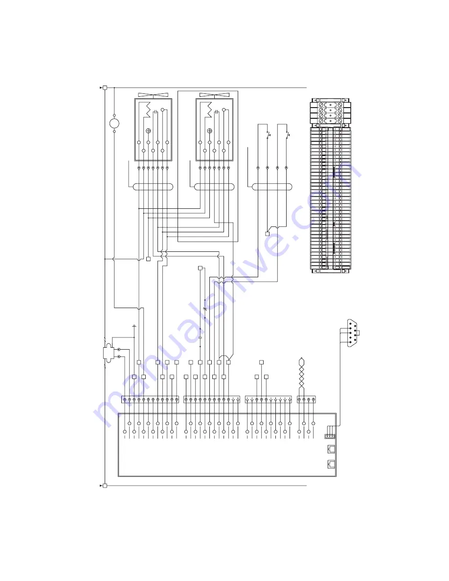
21
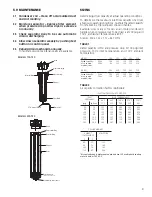
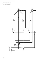
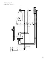
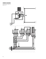
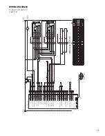
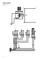
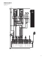
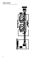
WIRING DIAGRAM
Model 750, (460 VAC)
Sheet 2 of 2