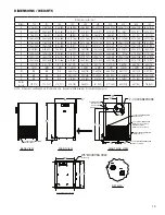
background image

4

1.2 Mounting 

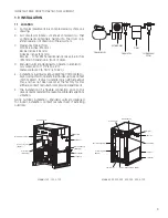
Mount the dryer on a level solid surface.  Holes are provided 

in the dryer base to permanently mount the dryer to the 

floor.

1.3 Piping connections 

A. 

Air Inlet

 - Connect compressed air line from air source 

to air inlet.  (Reference markings on dryer for air inlet/

outlet connection locations.)


Refer to Serial Number Tag for maximum working 

pressure.  Do not exceed dryer’s Maximum Working Pressure.

NOTE:  Install dryer in air system at highest pressure possible 

(e.g. before pressure reducing valves).
NOTE:  Install dryer at coolest compressed air temperature 

possible.  Maximum inlet compressed air temperature: 120°F 

(49°C).  If inlet air exceeds this temperature, precool the air 

with an aftercooler.  
B. 

Air Outlet

 – Connect air outlet to downstream air lines.

C. 

Bypass piping 

– If servicing the dryer without 

interrupting the air supply is desired, piping should 

include inlet and outlet valves and an air bypass valve.

D. 

Water cooled models

 – cooling water inlet and outlet

1.  Connect cooling water supply to cooling water inlet.

2.  Connect cooling water return line to cooling water 

outlet connection.

NOTE:  Strainer and water regulating valve are supplied on 

water cooled models.

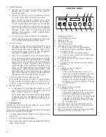
1.4 Electrical connections

IMPORTANT:  Use copper supply wires only.
A.


Dryer is designed to operate on the 

voltage, phase, and frequency listed on 

the serial number tag.

B.  If dryer is supplied with a cord and plug, 

install in a receptacle of proper voltage.

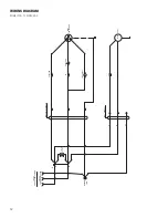
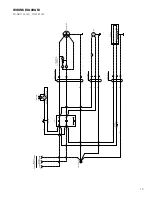
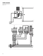
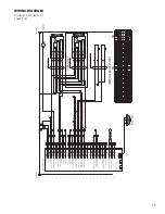
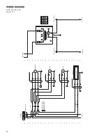
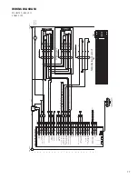
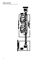
C.  Electrical entry on larger dryers is through a hole in 

the cabinet.  It is located on the right side panel when 

facing the front of the unit.  Connect power source to 

terminal strip in electrical enclosure as shown on the 

wiring diagram included with the dryer.

NOTE:  Refrigeration condensing unit is designed to run 

continuously and should NOT be wired to cycle on/off with 

the air compressor.
NOTE: ON MODELS 500, 600, and 750, CHECK FOR CORRECT 

PHASING OF UNIT.  After starting the dryer, if an unusual 

noise is heard, or if the discharge line does not get hot, the 

refrigeration compressor may be running in the reverse 

direction.  Immediately stop the dryer, reverse two of the 

power leads, restart the dryer, and verify the unusual noise is 

corrected and the refrigerant discharge line is hot.  FAILURE 

TO DO SO MAY DAMAGE THE COMPRESSOR AND VOID THE 

WARRANTY.

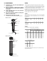
1.5 Moisture separator 

A. 

Models 100-150:


Separator (and Oil Removal Filter where 

applicable) has an internal drain which 

automatically discharges condensate.  


Models 200-750:


Separator (and Oil Removal Filter where applicable) has 

an electronic demand drain (EDD) which automatically 

discharges condensate.  

NOTE:  It may be desirable to pipe the condensate from the 

Automatic Drain outlet to a suitable drain.
B. 

Models 100-150:


Separator has a knurled fitting with flexible drain tubing 

attached.  Be sure knurled fitting is tightened by turning 

counter-clockwise before operating dryer.
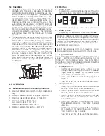
TO CLOSE

TURN COUNTERCLOCKWISE
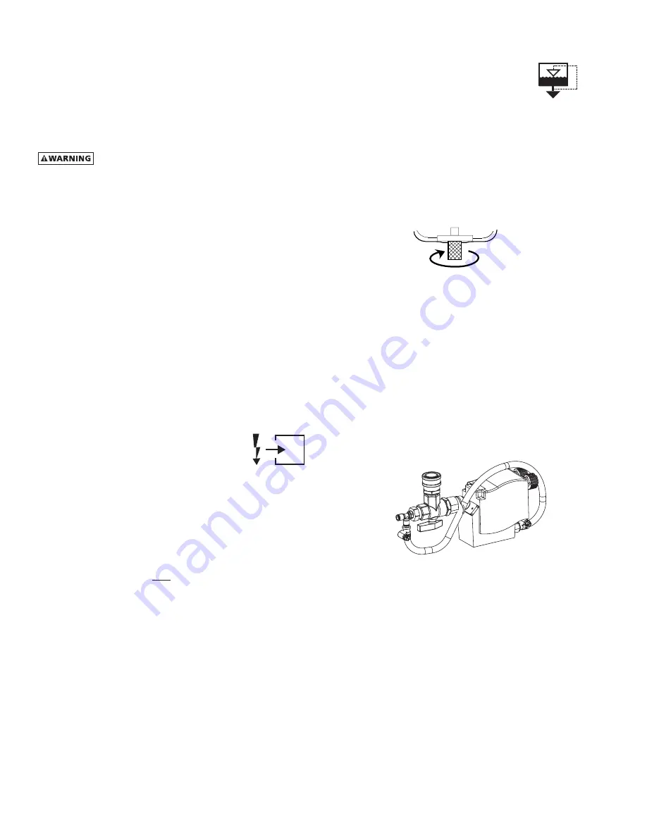
C. 

Models 200-750


For manual draining, convenient dryer depressurization, 

and EDD service, a three-way valve assembly has been 

installed at the bottom of the moisture separator (and 

cold coalescing filter where applicable).  Review the 

following for proper drain function:

•  Automatic  Draining  -  Valve  handle  should  be 

positioned parallel to the valve body (as shown), 

with the arrow on the handle pointing toward the 

EDD.  In this position, condensate will flow from the 

bowl to the EDD.

•  Drain Isolation (Shutdown) - Valve handle shall be 

turned perpendicular to the valve body (rotate 90°).  

In this position, condensate flow is shutoff.


•  Manual Draining - Drain valve handle shall be rotated 

slightly past the drain isolation position to allow 

throttling through the valve for manual discharge 

and depressuruzation.

• 

NOTE:  The quick disconnect fitting allows removal 

of the entire drain assembly.  

However, the unit 

must be depressurized prior to disassembly or 

serious injury may occur.

NOTE

:

  Discharge is at system pressure. Drain line should be 

anchored.
NOTE

:

  Condensate may contain oil. Comply with applicable 

laws concerning proper disposal.

Summary of Contents for Hankison HPRP Series

Page 1: ...yers Models HPRP100 HPRP125 HPRP150 HPRP200 HPRP250 HPRP300 HPRP400 HPRP500 HPRP600 HPRP750 FOR M NO 5002730 R EVI S ION 01 2012 R EAD AN D U N D E R STAN D TH I S MAN UAL PR IOR TO OPE RATI NG OR S E...

Page 2: ...r purification Refer to applicable standards and specifications for the requirements for breathing quality air RECEIVING MOVING AND UNPACKING A RECEIVING This shipment has been thoroughly checked pack...

Page 3: ...operate in altitudes up to 4500 feet 1370 meters If dryer is installed in an altitude above this and has not been preset at the factory for this altitude contact manufacturer s Service Department F T...

Page 4: ...the dryer if an unusual noise is heard or if the discharge line does not get hot the refrigeration compressor may be running in the reverse direction Immediately stop the dryer reverse two of the powe...

Page 5: ...F 43 C Water cooled models 130 F 54 C E Minimum ambient temperature 40 F 4 C 2 2 Start up A Models 100 150 Energize compressor by positioning the on off switch in the on I position Compressor on ligh...

Page 6: ...p and Down arrow buttons to set minutes 00 10 20 30 40 50 not shown if hour setting is IGNORE Press Enter to accept new value and return to Day of week on off Repeat steps a through c as needed d Push...

Page 7: ...l NOTE Interface panel will scroll through three screens Current Time Operating Status Hours to Service and Total Operating Hours a Verify that current time is correct b Check HRS TO SERVICE this indi...

Page 8: ...ake up to two seconds as certain processing functions may require completion before serial port is acknowledged Dryer responds with line feed 0AH carriage return 0DH and character string 1 2 3 4 5 6 7...

Page 9: ...110 F 120 F psig kgf cm2 27 C 32 C 38 C 43 C 49 C 50 80 100 125 150 175 200 3 5 5 6 7 0 8 8 10 5 12 3 14 0 1 35 1 50 1 55 1 63 1 70 1 75 1 80 1 05 1 17 1 23 1 31 1 37 1 42 1 47 0 84 0 95 1 00 1 07 1...

Page 10: ...A 1 1 2 0 50 Hz N A 0 9 1 7 Electrical Data Nominal Voltage 115 1 60 208 230 3 60 Min Max Voltage 104 127 187 253 Input Power Rated Flow watts 932 1280 1298 1255 1962 Rated Load Amps 10 2 13 0 7 5 10...

Page 11: ...low Required with 85 F Cooling Water gallons per minute 60 Hz 2 0 2 1 4 9 6 8 50 Hz 1 7 1 8 4 1 5 6 Electrical Data Nominal Voltage 208 230 3 60 Min Max Voltage 187 253 Input Power Rated Flow watts 19...

Page 12: ...STUD L2 L1 L2 230 VAC CUSTOMER SUPPLIED L1 PE PILOT LIGHT POWER ON T2 T2 T2 T1 T1 A PE T2 T1 T1 FPS 1 FAN 1 MTR2 START RELAY SR SR L3 L3 M 6 5 S CAPACITOR 4 OVERLOAD 3 1 3 MTR1 COMPRESSOR R C S POWER...

Page 13: ...CONT 1 PE PE L1 CONT 1 6 L2 GROUND STUD L2 L1 PE 230 VAC CUSTOMER SUPPLIED L1 L2 L2 L2 L1 L2 L1 L1 T2 T2 T1 T1 CONT 1 L1 N 4 5 5 A PE 6 FAN 1 HARNESS HEATER HARNESS PE L2 T2 T1 FPS 1 H1 H2 HEATER 1 MT...

Page 14: ...00 PE TB1 L1 L2 L3 L1 L1 460 VAC 3 PHASE 60 Hz L1 L2 L3 L1 CONT 1 T1 PE TB2 T1 T2 T3 T3 T2 T3 TB2 PE T2 T3 T2 FAN 1 HARNESS FPS 1 MTR2 FAN 1 MTR1 T1 T1 T1 COMPRESSOR HARNESS TO SHEET 02 43 42 X 40 41...

Page 15: ...W27 W18 W17 W16 N A N A W25 W23 FROM SHEET 01 01 03 02 00 Chassis Gnd TB2 X 24VAC IN 24VAC IN W3 W2 W1 X TB2 3 X REMOVE JUMPER IF OPTIONAL DRAIN INSTALLED 4NO TB2 TB2 TB2 TB2 TB2 19 20 21 18 17 19 20...

Page 16: ...VAC 3 PHASE 60 Hz TB1 L1 L3 L2 L1 CONT 1 T1 DISCONNECT SWITCH PE TB2 T1 T2 T3 T3 T2 T3 TB2 PE T2 T3 T2 FAN 1 HARNESS FPS 1 MTR2 FAN 1 MTR1 T1 T1 T1 COMPRESSOR HARNESS TO SHEET 02 43 42 X 40 41 39 38...

Page 17: ...put W27 W18 W17 W16 N A N A W25 W23 FROM SHEET 01 01 03 02 00 Chassis Gnd TB2 X 24VAC IN 24VAC IN W3 W2 W1 X TB2 3 X REMOVE JUMPER IF OPTIONAL DRAIN INSTALLED 4NO TB2 TB2 TB2 TB2 TB2 19 20 21 18 17 19...

Page 18: ...18 WIRING DIAGRAM Models 200 750 575 460 3 60 Transformer Pack...

Page 19: ...600 23 62 600 30 15 766 30 15 766 30 15 766 30 15 766 30 15 766 30 15 766 30 15 766 E 17 62 448 17 62 448 17 62 448 30 15 766 30 15 766 30 15 766 30 15 766 39 62 1006 39 62 1006 39 62 1006 F 19 62 49...

Page 20: ...emperature and pressure flow rate compressor capacity and ambient air or water temperature See D below B High pressure drop across dryer 1 Excessive air flow 2 Freezing of moisture in evaporator becau...

Page 21: ...of condenser cooling Air cooled Ambient temperature too high clogged condenser fins obstructed flow across condenser faulty fan motor or fan control switch Water cooled Cooling temperature too high f...

Page 22: ...5002016 Compressor Only 3221303 3232809 3221304 5002921 3227182 3210937 3211540 3210939 5002930 3232811 Fan Motor 3238932 3233153 3233153 5002922 3233153 3233152 3228005 3228005 5002931 3228005 Fan B...

Page 23: ...art THE FOREGOING WARRANTY IS EXCLUSIVE AND IN LIEU OF ALL OTHER WARRANTIES WHETHER WRITTEN ORAL OR STATUTORY AND IS EXPRESSLY IN LIEU OF THE IMPLIED WARRANTY OF MERCHANTABILITY AND THE IMPLIED WARRAN...

Page 24: ...ankisonintl com Improvements and research are continuous at Hankison an SPX Brand Specifications may change without notice ISSUED 01 2012 Form No 5002730 Revision A COPYRIGHT 2012 SPX Corporation HPRP...

Reviews: