background image


© 2022 Radiodetection Ltd 


32 

NOTE. To establish how often to take readings on the 

cable or pipe, move away from the ground stake and 

take further readings until the arrow has difficulty in 

locking and the dB reading is low. Measure the distance 

that the locator is now away from the ground stake. This 

is the distance that you can safely use between taking 

readings on the cable or pipe to ensure that you do not 

miss the fault. 

8.3 How to find a fault 

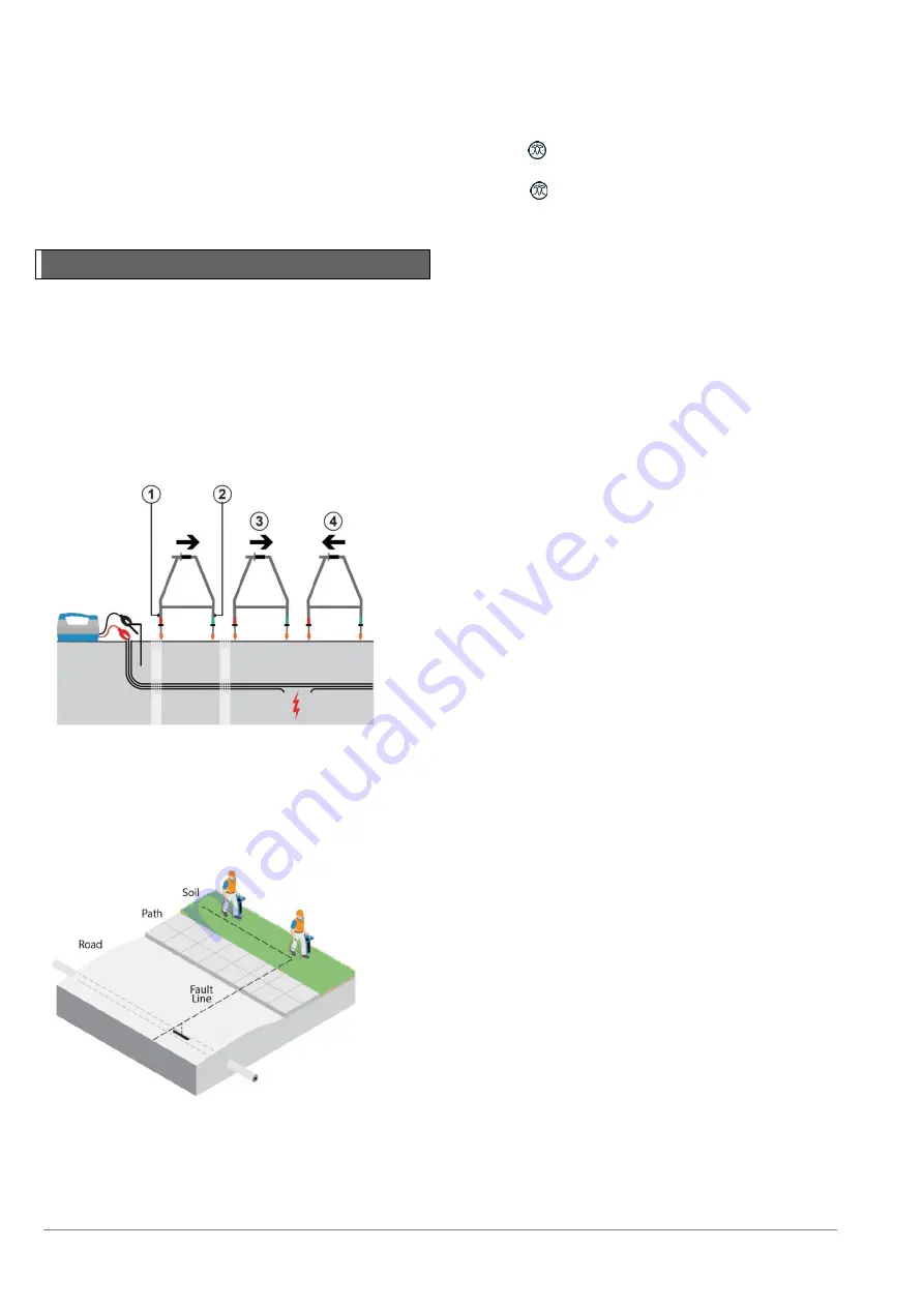
Starting from the transmitter, walk along the cable or 

pipe route pushing the A-Frame spikes into the ground 

with the green spike pointing away from the transmitter. 

Where there are no faults the dB reading will be low and 

the direction arrow may flicker forward and back. 

NOTE: Flickering arrows may also indicate that you may 

be too far away from the fault or ground stake (or both) 

for the locator to lock on. 


Figure 8.1: Cable sheath fault-finding


If you are trying to locate high resistance faults or there 

is a long distance between faults, carry on with the 

survey and the locator will lock on when you get closer 

to the fault. 


Figure 8.2: Locating faults with the locator and A-frame


Take readings at the survey intervals determined by the 

reference reading. To locate the cable or pipe while 

using the fault find signal during a Fault-Find survey, 
press


the


key


once


and


the


locator


will


switch


to


Peak locate mode. To use alternative antenna modes, 
press  the 

  key to step through available antenna 

modes. To get back to fault find mode step through all 

available antenna modes until the locator goes back to 

fault find mode. 

Note: While the A-Frame is  connected to the locator, 

depth and current measurements will not be available. If 

depth or current measurements are required, remove 

the A-Frame lead from the locator.  

As a fault is approached the Fault-Find direction arrow 

will lock on to the fault signal, point forward and the dB 

readings will increase. When the fault is passed the 

arrow will point back towards the transmitter. Take 

readings at smaller survey intervals to determine the 

exact point of the fault. 
When the A-frame is directly over the fault the dB 

reading will drop as shown opposite. 

NOTE: The values given are for illustration purposes 

only and may not be the same as those obtained in other 

situations. 

To pinpoint the fault, turn the A-frame 90° to the cable or 

pipe and Fault-Find until the exact point is found. Where 

the arrow direction changes the center line of the A-

frame is now directly over the fault. 
Mark the ground to show the position of the fault. Find 

the maximum dB reading in front of the fault by pushing 

the A-frame into the ground at small intervals. Note the 

dB reading. If the reading is approximately the same as 

the reference reading, you can assume that there is only 

one fault. If the reading is less than the reference 

reading, keep surveying the cable for other faults. 

NOTE: If the cable or pipe runs under a road, use the 

equipment as normal on the road surface as it can 

sometimes detect signals when working on blacktop, 

concrete, or paved surfaces. If necessary, try wetting the 

road surface. Pouring a very small amount of water 

around the bottom of the A-frame spikes before each 

Fault-Find will generally ensure a good ground 

connection. 

NOTE: If the cable or pipe runs under a paved surface, 

the fault can often be pinpointed by fault finding in the 

grass / soil adjacent to the paving. Reduce the distance 

between placing the A-frame spikes in the ground to 

allow for the increased distance to the actual fault 

position. 

Summary of Contents for RADIODETECTION RD7200

Page 1: ...RD7200 Precision utility Cable Pipe Locator Operation manual 90 RD7200 OM ENG 06 ...

Page 2: ... of frequency for active location 21 5 3 Antenna modes 22 5 4 Compass 23 5 5 Trace 23 5 6 Pinpoint 23 5 7 Sweep and search 24 5 8 Nulling Out 25 Section 6 Depth and current readings 26 6 1 TruDepth 26 6 2 Verifying depth measurements 26 6 3 Current readings 27 Section 7 Locating techniques 29 7 1 Identifying target utilities 29 7 2 Signal ground connection 30 7 3 Double ended connections 30 Sectio...

Page 3: ...on to live conductors is POTENTIALLY LETHAL Direct connections to live conductors should be attempted by fully qualified personnel only using the relevant products that allow connections to energized lines WARNING The transmitter is capable of outputting potentially lethal voltages Take care when applying signals to any pipe or cable and be sure to notify other technicians who may be working on th...

Page 4: ...posal service or product supplier Please dispose of this device in a manner appropriate to the relevant legal requirements at the end of its product life Batteries should be disposed of in accordance with your company s work practice and or the relevant laws or guidelines in your country or municipality 1 2 Compliance The Declaration of conformity is available to download from the RD7200 cable and...

Page 5: ...ower Filters RD Manager Online Peak StrikeAlert CALSafe The design of the RD7200 locators and transmitters has been registered The design of the 4 chevrons has been registered Windows is either a registered trademarks or trademarks of Microsoft Corporation in the United States and or other countries Due to a policy of continued development we reserve the right to alter or amend any published speci...

Page 6: ...notifications or just from receiving marketing material 2 4 Manual outline Section 1 includes an overview of safety procedures and notices Review them before moving on to Section 2 and the rest of this manual Section 3 provides an overview of the RD7200 system with annotated diagrams of the locator and transmitter Section 4 introduces basic setup and operation using the RD7200 locator s menu syste...

Page 7: ...quipment faulty and may void the manufacturer s warranty You are responsible for determining whether you consider the measurement results to be valid and for any conclusions that are reached or any measures that are taken as a result thereof Radiodetection can neither guarantee the validity of any measuring results nor can we accept liability for any such results We are on no account able to accep...

Page 8: ... 2022 Radiodetection Ltd 7 Section 3 System overview Figure 3 1 RD7200 Locator ...

Page 9: ...and Peak marker 17 Signal strength Numerical indication of signal strength 18 Null Proportional Guidance arrows Indicates the location of the line relative to the locator 19 Battery icon Indicates the battery level 20 Gain readout 21 Volume icon Displays the volume level 22 Radio Mode Indicates when Radio Mode is active 23 Power Mode Indicates when Power Mode is active 24 Accessory indicator Indic...

Page 10: ... 2022 Radiodetection Ltd 9 Figure 3 2 Tx Transmitter ...

Page 11: ...zardous voltage levels 19 Volume icon Displays the volume level 3 3 Using the menu The RD7200 locator and transmitter menus allow you to select or change system options Once entered the menu is navigated using the arrow keys Navigation is consistent on both the transmitter and the locator In the menu the options will appear in the bottom left hand corner of the display Note that when browsing the ...

Page 12: ...enu 4 Use the or keys to scroll through the submenu options 5 Press the key to confirm selection and return to the previous level or exit the menu 6 Press the key to return to the main operation screen Transmitter menu options VOL Adjust the speaker volume from 0 mute to 3 loudest FREQ Enable or disable individual frequencies BOOST Boost transmitter output for a specified period of time in minutes...

Page 13: ...r batteries On the transmitter To fit the D cell batteries in the transmitter unlatch the accessory tray The battery compartment see figure 3 2 is located underneath the transmitter body Use the turnkey to unlatch the battery compartment Insert eight D Cell Alkaline or NiMH batteries Figure 4 3 D cell battery trays Battery status The locator and transmitter displays provide a battery level indicat...

Page 14: ... battery pack If using the Li ion battery pack plug the lead into the battery connector fig 4 7 Figure 4 7 Connecting the Li Ion lead NOTE Fully charge your lithium ion battery pack before its first use Transmitter battery pack 1 Unlatch then remove the accessory tray Figure 4 8 Release then remove the accessory tray 2 Turn the release catch then open the battery compartment 3 Release the retainin...

Page 15: ...with or attempt to disassemble the battery packs CAUTION If battery failure is suspected or if the battery shows any sign of discoloration physical damage return the entire unit to an authorized repair center for investigation and repair Local national or IATA transport regulations may restrict the shipment of faulty batteries Check with your courier for restrictions and best practice guidelines Y...

Page 16: ... Take voltage and impedance measurements at a standardized frequency Adjusts the output signal Select standby maximum standard power Table 4 2 Transmitter key actions NOTE to scroll through frequencies from high to low hold while pressing the button applies to both locators and transmitters 4 4 Antenna modes The RD7200 locator supports 4 antenna modes to suit your particular application or the loc...

Page 17: ...return to the main operation screen 7 If you are using the optional Li Ion battery pack the locator will automatically select the correct battery type Power network frequency Select the correct frequency 50 or 60Hz for your country or region s power supply on your locator To change power frequency on the locator 1 Press the key to enter the menu 2 Scroll to the POWER menu using the or keys 3 Press...

Page 18: ...con Both the depth and current measurements will be disabled in the event of an overload 4 8 TruDepth measurement All RD7200 locators use TruDepth to measure depth automatically when a good quality reading can be assured NOTE TruDepth only indicates a locate depth when The locator is correctly oriented above the target line cable or sonde The local signal conditions are assessed as be good enough ...

Page 19: ...pauto and exit the OPTF Menu 6 Press the key to exit the menu NOTE SideStepauto has to be enabled for each Direct Connection using the START option At any time the user may manually change the frequency using the key 4 14 Transmitter power output The transmitter supports several power output modes to help you select the optimal settings for your requirements whilst helping to prolong battery life ...

Page 20: ...time the transmitter is switched off the transmitter will revert back to the default low voltage setting 4 17 Measure mode The transmitter has the capability of providing impedance measurements by determining the resultant impedance across the crocodile clips of the Direct Connection lead while connected to the utility These measurements can be useful when assessing sheath fault severity It is als...

Page 21: ...t directly to the utility The transmitter will then apply a discrete signal which you can locate using the locator This is the preferred method of applying a transmitter signal to a utility and in the majority of applications will apply a stronger signal to the utility which may increase the locate distance To directly connect to a non energized conductive utility 1 Switch the transmitter off 2 Co...

Page 22: ...easily to unwanted lines however it is too low for induction and it falls within the band of power frequency harmonic interference 8kHz Figure 5 3 8kHz active signal This medium frequency is the most useful general purpose signal high enough for induction outside the power frequency interference band and with limited coupling to wanted lines however it may not be high enough to impose a strong sig...

Page 23: ...ress the key to enter the menu 2 Scroll to the ARROW menu using the or keys 3 Press the key to enter the ARROW menu 4 Select NULL or GUIDE using the or keys 5 Press the key twice to return to the main locate menu When using Guidance arrows Use the proportional arrows to guide the locator along the path of the target cable or pipe To accurately locate the center point of the target utility for exam...

Page 24: ...line in Peak or Peak mode accurately defines the position of a target line after it has been traced and its position is approximately known Start with medium output power from the transmitter medium frequency on the transmitter and locator and Peak or Peak mode on the locator Set the locator sensitivity to approximately 50 by pressing the or key NOTE it may be necessary to adjust the sensitivity l...

Page 25: ...que for locating unknown lines This type of search requires a transmitter and locator and two people This type of search is referred to as a two person sweep Before starting the sweep define the area of search and the probable direction of lines crossing the area Ensure the transmitter is switched on in induction mode Figure 5 5 Inductive search The first person operates the transmitter and the se...

Page 26: ...d operator should hold the transmitter at waist level with the transmitter on its side release support arm pointing down 5 The transmitter is then moved from side to side to find the Null spot between two detectable signals the transmitter should then be lowered towards the ground keeping it in the Null spot 6 At ground level we are ideally looking for a Null no wider than 50mm 2 Sensitivity on th...

Page 27: ...lay depth and current in applicable modes when the locator is correctly orientated above the target line cable or sonde To ensure the locator is correctly orientated use the Compass feature When locating lines make sure the Compass display is in the North South orientation position When locating sondes see Section 8 5 make sure the Compass display is in the East West orientation Figure 6 1 Taking ...

Page 28: ...ect the same frequency as is selected on the transmitter but make sure that this frequency is in the sonde mode 3 Move the locator from left to right and when the bargraph reading is at its Peak note the depth as indicated on the locator Measure the distance from the base of the locator to the center of the transmitter using a tape measure 4 Compare this reading with the depth reading on the locat...

Page 29: ...only using the relevant products that allow connections to energized lines Signal current measurements Pinpoint the line and confirm the accuracy of the Peak pinpoint with null arrows Check the locator is directly over the line with the antennas at right angles to it and vertical The locator will automatically estimate and display depth on the LCD A signal coupled to a nearby line may distort the ...

Page 30: ...or to marking the wrong line A certain degree of coupling is unavoidable in many situations but there are ways in which a careful user can reduce coupling and increase location reliability Avoid applying the signal by induction The signal may be coupling to more than one line directly from the transmitter Use the signal clamp where possible Identify points where lines may be bonded or in close pro...

Page 31: ...t the best possible grounding for the transmitter This provides the lowest resistance ground path and the best output signal If it is not possible to use the ground stake the following are examples of good alternative ground points Metal manhole covers Metal drainage grates Metal railings Metal fence posts 7 3 Double ended connections Large diameter water pipes and gas distribution pipes that are ...

Page 32: ...connector to the ground stake ensuring that a positive connection is achieved NOTE Always connect the black connection lead to a ground stake and not a water pipe or buried cable as these may carry the signal Reference readings It is good practice to obtain a reference reading from the ground stake before you attempt to locate a fault on a target line Reference readings help to provide the followi...

Page 33: ...ts will not be available If depth or current measurements are required remove the A Frame lead from the locator As a fault is approached the Fault Find direction arrow will lock on to the fault signal point forward and the dB readings will increase When the fault is passed the arrow will point back towards the transmitter Take readings at smaller survey intervals to determine the exact point of th...

Page 34: ...rs in the field such as moving traffic or other heavy machinery Exercise caution 9 3 Locator clamps A locator clamp is used to positively locate and identify a cable when several cables are running close together A target cable can be identified in a chamber on a tray or other access point by fitting a clamp to the locator and examining each cable in turn Signal strength response shown on the loca...

Page 35: ...ound a power cable that has significant net current flow This is normal and does not harm the equipment Connecting the clamp Figure 9 3 Transmitter output socket 7 Plug the clamp into the transmitter output socket 8 Put the clamp around the pipe or cable and ensure that the jaws are closed Switch the transmitter on The display will show the Clamp connected icon Figure 9 4 Clamp connected icon The ...

Page 36: ... a suitable sonde Radiodetection offers a wide range of sonde to suit most applications From the 6mm diameter S6 33kHz microsonde which with a range of 6 6 2m targets fiber optic micro ducting or other small non conductive pipes to the 33kHz Super Sonde which with a depth range of 50 feet 15m targets deep sewer pipes Consult the precision locate accessory range brochure or web page on www radiodet...

Page 37: ...ivity level Figure 9 7 Sonde deployment To locate a sonde 1 Move the locator backwards and forwards and stop when the bar graph indicates a Peak You can use the LCD compass to orient the blade of the locator with the direction of the sonde 2 Rotate the locator as if the blade is a pivot Stop when the bar graph indicates a Peak Figure 9 8 Locating a sonde 3 Move the locator from side to side until ...

Page 38: ...able in turn to detect a maximum signal Stethoscope range Large stethoscope antenna The large stethoscope antenna which plugs into the locator accessory socket is used for cable identification in situations where the cable is exposed It is particularly useful for identifying heavy cables lying in a tray where it is not possible to fit a clamp The concave detector head on the end of the insulated f...

Page 39: ...ft from the transmitter Test the quality of signal on the line before locating on the water NOTE The submersible antenna is calibrated to work at one frequency Tips for using a submersible antenna The user in the boat should be a specialist or have considerable experience using a locator so that they can give concise instructions to the diver It is prudent for the pair to practice working together...

Page 40: ...d repair center Regularly check your locator for correct operation using eCert see section 10 6 and the on board Self Test NOTE Service by non approved service centers or operators may void the manufacturer s warranty Radiodetection products including this guide are under continuous development and are subject to change without notice Go to www radiodetection com or contact your local Radiodetecti...

Page 41: ...able to opt out at any moment from receiving software and technical notifications or just from receiving marketing material 10 5 Upgrading software From time to time Radiodetection may release software upgrades to enhance features and improve performance of the RD7200 locator or transmitter Software upgrades are free of charge You can check if your products are up to date or upgrade them by using ...

Page 42: ... Induction Clamp CD Clamp LPC LCC 8kHz 8192Hz DC Induction Clamp LPC LCC 9 8kHz 9820Hz DC Induction Clamp CD Clamp LPC LCC 33kHz 32 768Hz DC Induction Clamp LPC LCC 65kHz 65 536Hz DC Induction Clamp CD Clamp LPC LCC 83kHz 83 000Hz DC Induction Clamp CD Clamp LPC LCC 83kHz 83 077Hz DC Induction Clamp CD Clamp LPC LCC 131kHz 131 072Hz DC Induction Clamp CD Clamp LPC LCC 200kHz DC Induction Clamp CD ...

Page 43: ...scope 10 RX STETHOSCOPE L 640Hz Submersible DD Antenna 10m Cable 10 RX SUBANTENNA 640 8kHz Submersible DD Antenna 10m Cable 10 RX SUBANTENNA 8K 512Hz Submersible DD Antenna 10m Cable 10 RX SUBANTENNA 512 Additional Submersible Cable Length x meter 10 RX SUBANTENNA CABLE Submersible Antenna Adaptor 10 RX SUBANTENNA ADAPTOR Headphones 10 RX HEADPHONES A Frame includes A Frame Lead 10 RX AFRAME A Fra...

Page 44: ...odile clips 10 TX LCC 2 50mm Transmitter Clamp 10 TX CLAMP 2 or 10 TX CLAMP 50 4 100mm Transmitter Clamp 10 TX CLAMP 4 or 10 TX CLAMP 100 5 130mm Transmitter Clamp 10 TX CLAMP 5 or 10 TX CLAMP 130 8 5 215mm Transmitter Clamp 10 TX CLAMP 8 5 or 10 TX CLAMP 215 Signal Clamp Extension Rod 10 TX CLAMP EXTROD Transmitter Connection Kit Contains Earth Reel Earth Stake Direct Connection Lead and Magnet 1...

Page 45: ...lug socket 10 TX DC LEAD BAN Tx Direct Connection Lead with banana connectors Open Grid Europe 10 TX DC LEAD OPEN Tx 10 Isolation Transformer for locating 3 phase core core shorts 10 TX121 XX XX DE EN FR NL Accessories for tracing or locating non conductive utilities Standard Sonde 33kHz depth up to 5m 10 SONDE STD 33 Standard Sonde 8kHz depth up to 5m 10 SONDE STD 8 Standard Sonde 512Hz depth up ...

Page 46: ...ps two Batteries and Case 10 SONDE S13 33 Pack of ten spare Batteries for S13 Sonde 10 SONDE S13 BATPACK S18A Sonde 33kHz with M10 Stud End Cap and one D1 3N battery 10 SONDE S18A 33 S18A Sonde 33kHz Kit with M10 Stud and Plain End Caps and two D1 3N Batteries 10 S18 33 KIT S18A M10 Stud End Cap with one D1 3N Battery 10 S18 M10 ENDCAP S18A Extended Plain Cap with one D1 3N Battery 10 S18 PLAINEND...

Page 47: ...xrod 10 FLEXRODF50 4 5 4 5mm 80m Flexrod 10 FLEXRODF80 4 5 6 7mm 50m Flexrod 10 FLEXRODF50 7 6 7mm 100m Flexrod 10 FLEXRODF100 7 6 7mm 150m Flexrod 10 FLEXRODF150 7 9mm 60m Flexrod 10 FLEXRODF60 9 9mm 120m Flexrod 10 FLEXRODF120 9 M6 to M10 adapter to interface 6 7mm rod with RD M10 thread 10 6 10FLEXRODADAPTOR Spring Coupling M10 Male 10 SU0335 Wards Rod Connector 3 4 19mm x 10 BSW Female 02 SU03...

Page 48: ... MRX Locators 2 Compatible with RD7200 RD8200 RD7100 RD8100 and RD7000 RD8000 Locators Replace XX with AU EU UK or US Transmitter power accessories and spares Mains PSU includes power lead 10 TX MPSU XX 12V Car Power Lead with Isolation Transformer 10 TX APSU Li Ion rechargeable battery pack with mains charger includes power lead 1 10 TX MBATPACK LION K XX Li Ion rechargeable battery pack with aut...

Page 49: ...ION 8 cells battery tray 8x D Cell LR20 10 TX 8DCELL TRAY 1 Li Ion rechargeable packs cannot be charged in the transmitter Replace XX with AU EU UK or US Mains Leads C7 Mains lead 6 5 2m 2 5A 10 MAINS LEAD C7 XX C13 Mains lead 6 5 2m 2 5A 10 MAINS LEAD C13 XX Replace XX with AU EU UK or US ...

Page 50: ...TX BAG Locator and Tx transmitter soft carry bag 10 LOCATORBAG Locator and Tx transmitter hard case 10 RD7K8KCASE USA Locator and Tx transmitter hard flight case with wheels 10 RD7K8KCASE Calibration Certificates Remote Calibration and PC Software Locator Calibration Certificate per unit requestable with initial locator order cannot be ordered later 10 CALCERT RD Manager Online Check product docum...

Page 51: ...ublished specification without notice This document may not be copied reproduced transmitted modified or used in whole or in part without the prior written consent of Radiodetection Ltd 90 RD7200 OM ENG 06 Visit www radiodetection com Follow us on USA Raymond ME Kearneysville WV Canada Vaughan ON Mississauga ON Europe United Kingdom HQ France Germany The Netherlands Asia Pacific India China Hong K...

Reviews: