background image

Model SR255 Daily-Weigh

 Scale 

Operating and Service Manual - S/N 3616+ 
Part No. MAN255_110921 


Page 14 of 22 


S

Instruments, Inc.

600 Young Street, Tonawanda, NY  14150 

Tel:  716-693-5977     Fax:  716-693-5854    URL:  

www.srscales.com


email:  

sri@srinstruments.com

     Copyright 2011


S

Instruments, Inc. 

BASIC SYSTEM OPERATION Cont’d 


STEP 3

: (Figure 

13) 


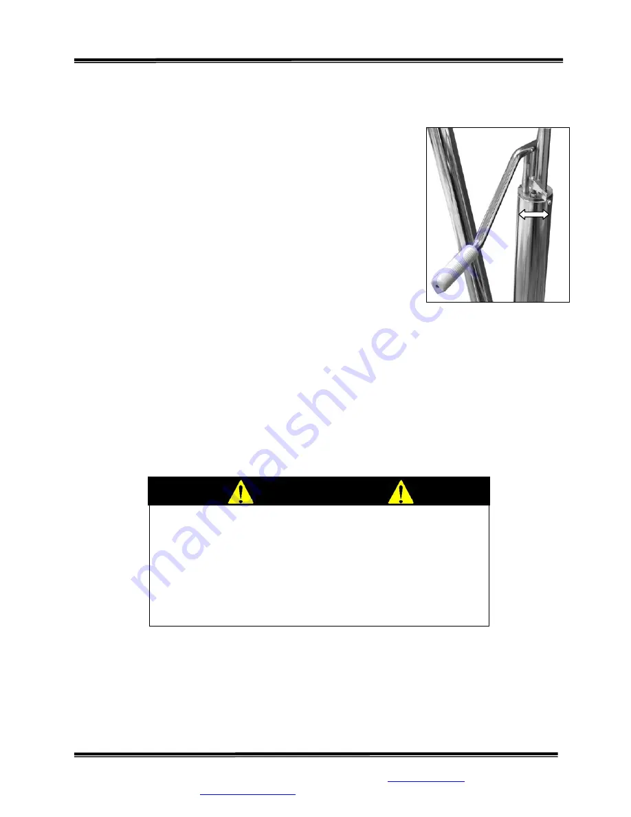
To RAISE the T-Boom

, the Lock/ Release 

Lever on the lifter must be in the LOCK position (left).  Pump the 
handle.  

To LOWER the T-Boom

, the Lock/Release lever on the lifter 

must be in the RELEASE position (right).  Patient’s weight will slowly 
lower the T-Boom.  

STEP 4

:  With the T-Boom raised, roll the scale forward so the two 

(2) A-Frames are centered over the patient.  Lower the T-Boom and 
attach the A-Frame hooks into the Stretcher holes.  Move the lever 
into the LOCK position.  DO NOT EXCEED THE MAXIMUM 
CAPACITY OF 400 LB/ 181 KG.


STEP 5

:  When the Stretcher is securely attached, pump handle until 

the patient is raised just enough to clear the bed and any linens, etc.  
Weigh patient and when finished, lower back on to the bed by moving 
the Lock/Release Lever to RELEASE (right).  Patient’s weight will 
lower the Stretcher slowly.  Unhook the Stretcher and again raise the T-
Boom so the patient can be safely moved.


DO NOT ATTEMPT TO 

TRANSPORT PATIENT VIA THE SCALE! 

STEP 6

:  It is recommended that you re-zero before each weighing to ensure optimal accuracy. 

NOTE: 

Do not touch patient, stretcher or circular A-Frames during the weighing process.  By 

design, these components are weight sensitive and any interference will affect the accuracy of the 
weight data. 


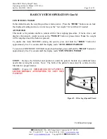
Figure 13:  Lifter LOCK/ 

RELEASE Lever 

WARNING 

„


DO NOT USE FOR PATIENT TRANSPORT. 

„


MAXIMUM 400 LB / 181 KG CAPACITY 

„


SPREAD THE LEGS OF THE LIFTER BASE PRIOR 
TO LIFTING AND WEIGHING PATIENT  
Failure to spread the legs prior to suspending patient 
could bend legs or cause lifter to tip over and injure 
patient and/or attendant. 

Summary of Contents for Daily-Weigh SR255

Page 1: ...921 Page 1 of 22 SInstruments Inc 600 Young Street Tonawanda NY 14150 Tel 716 693 5977 Fax 716 693 5854 URL www srscales com email sri srinstruments com Copyright 2011 SInstruments Inc Operating and S...

Page 2: ...011 SInstruments Inc TABLE OF CONTENTS TABLE OF FIGURES 3 PACKING CHECKLIST SR255 ADULT 4 PACKING CHECKLIST SR255 PEDIATRIC 5 ASSEMBLY 6 REPLACEMENT PARTS AND ACCESSORIES 8 SYSTEM DESCRIPTION AND INTE...

Page 3: ...in Receptacle 7 Figure 5 T Boom Lifter Pump Connection 7 Figure 6 Transducer Connected to T Boom 7 Figure 7 Transducer Cable Connection 7 Figure 8 Transducer A Frame Connected 7 Figure 9 Velcro End o...

Page 4: ...SHOULDER BOLT for T Boom Pump Assy 1 ea WASHER for T Boom Pump Assy 1 ea 3 8 16 LOCK NUT for T Boom Pump Assy 1 ea SPREADER BAR 1 ea TRANSDUCER TUBE 1 ea 6 32 x SOCKET HEAD CAP SCREW Safety Screw Tra...

Page 5: ...1 SHOULDER BOLT for T Boom Pump Assy 1 ea WASHER for T Boom Pump Assy 1 ea 3 8 16 LOCK NUT for T Boom Pump Assy 1 ea SPREADER BAR 1 ea TRANSDUCER TUBE 1 ea 6 32 x SOCKET HEAD CAP SCREW Safety Screw T...

Page 6: ...play Unit 3 matches that on the Transducer Bar 6 STEP 3 Figure 2 Attach the Stretcher Cup 15 to the Invacare Lifter Base 1 snapping it into place and twisting the lower tab back under the Mast 12 past...

Page 7: ...t in place on Invacare Lifter Base STEP 6 Figure 5 Attach and securely tighten the rod end of the Lifter Pump 7 to the T Boom 5 using 3 8 16 x 1 in shoulder bolt washer and 3 8 16 lock nut All are shi...

Page 8: ...the Display to hold it upright STEP 11 Figure 10 The Stretcher attaches to the A Frames by inserting their hooked ends through the four holes in the Stretcher REPLACEMENT PARTS and ACCESSORIES Figure...

Page 9: ...be viewed in either pounds or kilograms with a displayed resolution of 0 1 lb or 0 1 kg INTENDED USE The SR255 Daily Weigh Scale is designed for use as a patient weighing system for non ambulatory pat...

Page 10: ...ove the batteries To maintain proper operation of this instrumentation storage and transport conditions should not vary outside the following conditions Relative humidity 0 to 85 Ambient Temperature 1...

Page 11: ...AUTO ZERO One button operation AUTO POWER DOWN After 35 seconds HOLD While active freezes display data and stores it in memory LAST WEIGHT RECALL Hold button recalls last stored weight AVERAGING Auto...

Page 12: ...displayed weight and temporarily stores it away in memory Press HOLD to store the weight into memory To recall last weight reading press HOLD LB KG MODE Weight data may be viewed in either pounds or...

Page 13: ...nd displays the patient s weight as soon as the WEIGH button is pressed once Note No weight will be displayed until the button is pressed To enable this mode BEFORE zeroing the system press and hold t...

Page 14: ...KG STEP 5 When the Stretcher is securely attached pump handle until the patient is raised just enough to clear the bed and any linens etc Weigh patient and when finished lower back on to the bed by mo...

Page 15: ...EMENT STEP 1 The display will read CHANGE BATTERY when the batteries are low STEP 2 Unscrew the four 4 screws and open the Battery Compartment Cover on the front of the Display Unit STEP 3 Remove and...

Page 16: ...nalog to digital converter The converter integrates the analog signal onto the integrating capacitor over a short interval The integrating capacitor is then discharged at a rate proportional to the re...

Page 17: ...STEP 3 The display will read HOLD TO CAL as the digit in the right hand corner counts down from 9 to 0 The display will then read CALIBRATION and periodically flash this on the display In the far lef...

Page 18: ...T on the stretcher and compare to display reading STEP 7 Adjust the reading using the or buttons to match the weight Display should be within 0 1 of the calibrated weight See Calibration Tolerance Tab...

Page 19: ...e seconds then re install the battery and try the WEIGH button again The display lights appear to work but does not respond to button activation Button may not have bounced back up after being pressed...

Page 20: ...c s part and it neither assumes nor authorizes any other person to assume for SR Instruments Inc any other liabilities in connection with the sale of said articles In no event shall SR Instruments Inc...

Page 21: ...and Service Manual S N 3616 Part No MAN255_110921 Page 21 of 22 SInstruments Inc 600 Young Street Tonawanda NY 14150 Tel 716 693 5977 Fax 716 693 5854 URL www srscales com email sri srinstruments com...

Page 22: ...6 Part No MAN255_110921 Page 22 of 22 SInstruments Inc 600 Young Street Tonawanda NY 14150 Tel 716 693 5977 Fax 716 693 5854 URL www srscales com email sri srinstruments com Copyright 2011 SInstrument...

Reviews: