background image

Model SR7010

i

 Wall Mount Platform Scale 

Operating and Service Manual  
Part No. MAN7010

i

 _150908 


Page 10 of 14 


S

Instruments, Inc.

600 Young Street, Tonawanda, NY  14150 

Tel:  716-693-5977     Fax:  716-693-5854    URL:  

www.srscales.com


email:  

sri@srinstruments.com

       Copyright 2015


S

Instruments, Inc. 

L O W  

L IM IT

A P P L IE D  

L O A D

H IG H  

L IM IT

  9 9 .9

  1 0 0 .0

  1 0 0 .1

1 9 9 .8

  2 0 0 .0

  2 0 0 .2

2 9 9 .7

  3 0 0 .0

  3 0 0 .3

3 9 9 .6

  4 0 0 .0

  4 0 0 .4

4 9 9 .5

  5 0 0 .0

  5 0 0 .5

5 9 9 .4

  6 0 0 .0

  6 0 0 .6

6 9 9 .3

  7 0 0 .0

  7 0 0 .7

7 9 9 .2

  8 0 0 .0

  8 0 0 .8

8 9 9 .1

  9 0 0 .0

  9 0 0 .7

9 9 9 .0

  1 0 0 0 .0

1 0 0 1 .0

C A L IB R A T IO N  

T O L E R A N C E  T A B L E


CALIBRATION 


NOTE:

  Ensure that nothing is in contact with the scale system during 

this  procedure.    Remove  hands  from  the  system  when  noting  the 
displayed calibration results. 

 
CHECKING CALIBRATION 
 
STEP 1:

  Select known calibrated weights, traceable to NIST.   

NOTE: DO NOT USE

 barbells or uncalibrated weights. 

STEP 2:

  Zero the scale by pressing and holding the left 

ZERO 

button. 

STEP  3:

    Place  the  calibrated  weight  on  the  scale.    Wait  for  scale  to 

stabilize; note scale reading. 

STEP 4:

  Scale readings should be within Calibration Tolerance Table 

(

Figure 3


Figure 3:    Calibration Table 

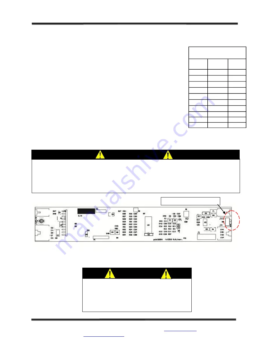
Figure 4:    Calibration Switch Diagram 

IMPORTANT 

CALIBRATION  Qualified  service  personnel  only  should  perform  this  procedure.    The 
SR7010

i

 load cells have no user serviceable components and should not be tampered with 

for  any  reason.    Re-calibration  is  generally  not  required,  but  should  be  verified 
periodically  to  ensure  accuracy.    The  recommendation  for  calibration  check  is  at  least 
once every 12 months, or as individual maintenance policy requires. 


CALIBRATION SWITCH


CAUTION 

The  integrated  circuits  and  semiconductors  on 
the  printed  circuit  boards  may  be  damaged 
by  electrostatic  discharge  (ESD).    Be  sure  to 
use proper handling precautions at all times.  

Continued next page 

Summary of Contents for SR 7010i

Page 1: ...0i _150908 Page 1 of 14 SInstruments Inc 600 Young Street Tonawanda NY 14150 Tel 716 693 5977 Fax 716 693 5854 URL www srscales com email sri srinstruments com Copyright 2015 SInstruments Inc S by S Instruments Inc Operating and Service Manual Model SR 7010i Wall Mount Platform Scale ...

Page 2: ... Inc TABLE OF CONTENTS TABLE OF FIGURES 2 PACKING CHECKLIST 3 ASSEMBLY 3 REPLACEMENT PARTS AND ACCESSORIES 4 SYSTEM DESCRIPTION AND INTENDED USE 5 MAINTENANCE AND CLEANING 5 STORAGE 5 SPECIFICATIONS 6 BUTTON FUNCTIONS 7 BUTTON FUNCTIONS CON T 8 BASIC SYSTEM OPERATION 8 THEORY OF OPERATION 9 CALIBRATION 10 TROUBLESHOOTING 12 WARRANTY 13 TABLE OF FIGURES Figure 1 Wall Hanger 3 Figure 2 Button Displa...

Page 3: ...ll Mount Platform Scale use the Wall Hanger Figure 1 supplied with the scale NOTE The Wall Hanger should be installed by qualified personnel STEP 3 Mount the Wall Hanger by placing the SR7010i scale in an upright position against the wall at the location for installation Place the SR7010i wall frame 3 x 1 cross member into the channel of the Wall Hanger NOTE The Wall Hanger is not intended to supp...

Page 4: ...l Hanger is pressed against the bottom of the cross member STEP 5 Using the Wall Hanger as a template mark the location of the four 4 Wall Hanger holes on the wall STEP 6 Remove the Wall Hanger and drill four 4 pilot holes no larger than diameter in the locations marked Install the four 4 Self Drilling Screw Anchors STEP 7 Position the Wall Hanger on the wall frame cross member Screw the Wall Hang...

Page 5: ...mable Automatic Power Down APD for adjusting scale on time INTENDED USE The SR7010i Wall Mount Platform Scale system is specifically designed for weighing ambulatory and non ambulatory stretcher and wheelchair bound patients and is a preferred means of gathering patient weight data of up to 1000 pounds or 454 kilograms MAINTENANCE and CLEANING SR7010i Wall Mount Platform Scale system is made of po...

Page 6: ... Auto Zero when platform is first put down One button operation after platform is left down AUTO POWER DOWN Adjustable between 30 to 300 seconds AVERAGING Automatic digital filter POWER SUPPLY AC Wall Power Supply UL recognized CALIBRATION Calibration is traceable to NIST standards OPERATING CONDITIONS Normal operating conditions for this product Ambient Temperature Range 68 F to 85 F 20 C to 30 C...

Page 7: ...ss to recall the last stored weight The stored weight will be erased when the scale is zero or another stable weight is stored BMI Press to calculate BMI When the BMI is pressed the default value HT 65 in or HT 165 cm is displayed If there is no stored stable weight the display will indicate NO WEIGHT DATA and then go back to the weigh screen WT 0 0 Lb MENU Press Menu to toggle through the menu op...

Page 8: ...ing time and date BASIC SYSTEM OPERATION SETTING SYSTEM ZERO Scale will auto zero when the platform is first lowered Make sure the scale is free and clear of any obstructions When platform is left down press and hold the ZERO WEIGH button The displayed message will indicate HOLD TO ZERO and count down to zero Release the button when display message indicates HANDS OFF Make sure that nothing is in ...

Page 9: ...mplifier is configured to current sum the output of each cell with potentiometers serving to normalize the sensitivity voltage out per unit of weight applied of each bridge The offset potentiometer produces a small current which nulls the output of the amplifier for an unloaded system The output of the operational amplifier is digitized by the analog to digital converter The sigma delta converter ...

Page 10: ...NIST NOTE DO NOT USE barbells or uncalibrated weights STEP 2 Zero the scale by pressing and holding the left ZERO button STEP 3 Place the calibrated weight on the scale Wait for scale to stabilize note scale reading STEP 4 Scale readings should be within Calibration Tolerance Table Figure 3 Figure 3 Calibration Table Figure 4 Calibration Switch Diagram IMPORTANT CALIBRATION Qualified service perso...

Page 11: ...ave changes Press WEIGH button to abort any changes STEP 4 Press the MENU button until 500 0Lb HALF is displayed NOTE The Half Scale value is a value between zero and the Full Scale values It is usually close to half the Full Scale value Set the HALF value to the actual quantity of calibrated weight being used for Half Scale Use the UP arrow button to select the digit and the DOWN arrow button to ...

Page 12: ... button or disconnect power Wait five seconds then re connect the power and try the WEIGH button again The display lights appear to work but do not respond to button activation Check to ensure the membrane switch label is correctly plugged into display board Check to ensure the calibration switch is not in the Calibration Mode Figure 4 The display shows no reading at all Check that wall power supp...

Page 13: ... Inc s part and it neither assumes nor authorizes any other person to assume for SR Instruments Inc any other liabilities in connection with the sale of said articles In no event shall SR Instruments Inc be liable for any subsequent or special damages Any misuse improper installation or tampering shall void this warranty DAMAGED SHIPMENTS Title passes to purchaser upon delivery to Transportation C...

Page 14: ... Part No MAN7010i _150908 Page 14 of 14 SInstruments Inc 600 Young Street Tonawanda NY 14150 Tel 716 693 5977 Fax 716 693 5854 URL www srscales com email sri srinstruments com Copyright 2015 SInstruments Inc S by SInstruments Inc Precision Technology in Perfect Balance ...

Reviews: