background image

Model SRV947IFS 24 X 48 Remote Display Platform Scale 
Operating and Service Manual 
Part No.:  MAN947IFS_160129 


Page 4 of 12 


S

Instruments, Inc.

600 Young Street, Tonawanda, NY  14150 

Tel:  716-693-5977     Fax:  716-693-5854    URL:  

www.srscales.com


email:  

sri@srinstruments.com


Copyright 

2016


S

Instruments, Inc. 

ASSEMBLY 


STEP 1

:  Unpack  the  scale  system  and  check  parts 

against  the 

PACKING  CHECKLIST

.    If  there  are 

any missing or damaged parts, please call the Service 
Hotline at:  1-800-654-6360. 

STEP 2

:  Verify that the serial number on the label of 

Wall Box Display matches that on Platform Base.  

STEP  3

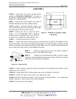
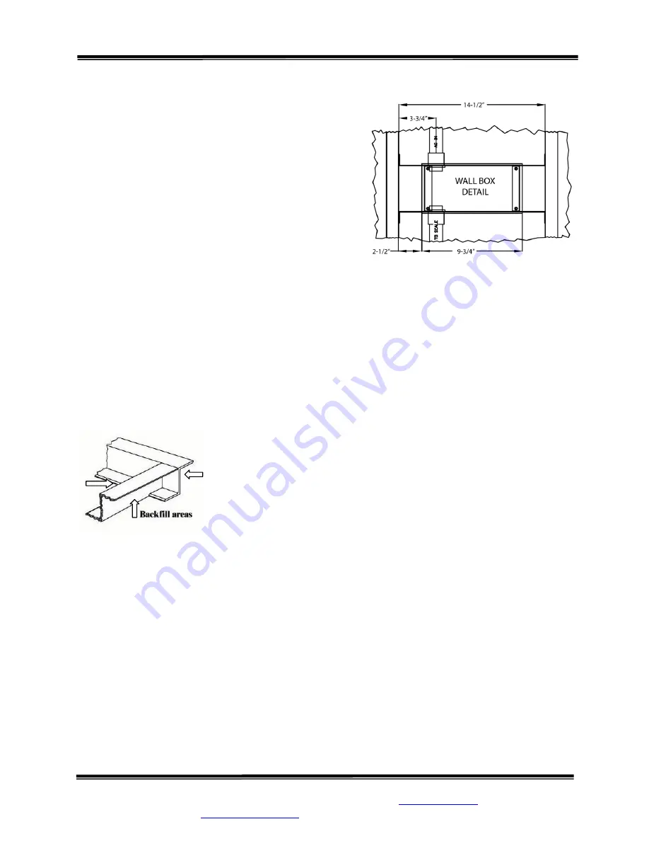
:  (Figure  1)  Mount  Wall  Box  Display  into 

wall and run the conduit, with connector cable inside, 
down through wall and into pit as shown.  

STEP 4

:  Prepare  pit  area  to  accept  the  Scale 

Frame.    It  is  recommended  that  a  properly 
plumbed  drain  be  installed  in  the  center  of  pit  to 
avoid any water buildup that might damage scale. 

STEP 5

:  Center the Scale Frame in the pit. 

STEP 6

(Figure 2) Back fill around the perimeter of the Pit Frame Assembly with 3000PSI concrete.  

Trowel the concrete level with the scale frame and existing floor.  Trowel the base of the pit level with 
the base of the frame with a gradient toward the centered drain, if used.  Conduit and cable should be left 
free so cable can be easily connected to the Platform Assembly. 
 

STEP 7

When the concrete has set, connect the Cable Assembly to 

the mating connector on the Platform Assembly. 

STEP 8

Carefully  lower  the  Platform  Assembly  into  the  Pit  Frame 

Assembly.  Ensure that Platform feet set into locators on Pit Frame and that 
extra cable does not interfere with platform. 


STEP 9:

  Install  building  ground  wire  and  green ground wire from  Display  Front Plate  into the 

terminal lug in the wall box 

STEP 10: 

Connect signal cable to the mating connector on the Display Front Panel 

STEP 11:

  Connect A/C power wires to the power supply wire leads 

STEP 12:

  Install Front Panel Assembly to the previously mounted Wall Box.  Use supplied star 

washers and screws.  Ensure screws are securely tightened. 

STEP 13:

  Restore power to the display


Figure 1:  Wall Box Assembly/Conduit 

Placement 

Figure 2:  Concrete Fill


Summary of Contents for SRV947IFS

Page 1: ... MAN947IFS_160129 Page 1 of 12 SInstruments Inc 600 Young Street Tonawanda NY 14150 Tel 716 693 5977 Fax 716 693 5854 URL www srscales com email sri srinstruments com Copyright 2016 SInstruments Inc SRV947IFS REMOTE DISPLAY PLATFORM SCALE S by SR Instruments Inc Operating and Service Manual ...

Page 2: ...truments Inc TABLE OF CONTENTS TABLE OF FIGURES 2 PACKING CHECKLIST MODEL SRV947IFS 3 ASSEMBLY 4 REPLACEMENT PARTS AND ACCESSORIES 5 SYSTEM DESCRIPTION AND INTENDED USE 5 MAINTENANCE AND CLEANING 6 STORAGE AND TRANSPORTATION 6 SPECIFICATIONS 7 BUTTON FUNCTIONS 8 BASIC SYSTEM OPERATION 9 CALIBRATION 10 TROUBLESHOOTING 10 WARRANTY 11 TABLE OF FIGURES Figure 1 Wall Box Assembly Conduit Placement 4 Fi...

Page 3: ... 14150 Tel 716 693 5977 Fax 716 693 5854 URL www srscales com email sri srinstruments com Copyright 2016 SInstruments Inc PACKING CHECKLIST Model SRV947IFS Portable Platform Scale DESCRIPTION QUANTITY PLATFORM PIT FRAME ASSEMBLY 1 ea FRONT PANEL WALL BOX ASSEMBLY 1 ea SIGNAL CABLE ASSEMBLY 1 ea CONDUIT 1 ea CALIBRATION CERTIFICATE 1 ea WARRANTY CARD 1 ea MANUAL 1 ea ...

Page 4: ...ill around the perimeter of the Pit Frame Assembly with 3000PSI concrete Trowel the concrete level with the scale frame and existing floor Trowel the base of the pit level with the base of the frame with a gradient toward the centered drain if used Conduit and cable should be left free so cable can be easily connected to the Platform Assembly STEP 7 When the concrete has set connect the Cable Asse...

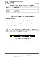
Page 5: ... technology to provide accurate and repeatable weight data Six 6 identically matched transducers are strategically placed to ensure an accurate representation of the patient s weight The patient s weight is displayed on an LCD screen With a push of a button weight data may be viewed in either pounds or kilograms INTENDED USE The SRV947IFS Portable Platform Scale is a lightweight portable scale des...

Page 6: ... cleaners Mild soap and water is recommended for general cleaning and disinfecting STORAGE and TRANSPORTATION STORAGE To maintain proper operation of this instrument storage and transport conditions should not vary outside the following conditions Relative Humidity 0 to 85 Ambient Temperature 14 F to 122 F 10 C to 50 C TRANSPORTATION The SRV947IFS Portable Platform Scale has four 4 recessed handle...

Page 7: ...LAY RESOLUTION 0 2 lb 0 1 kg ACCURACY 0 2 2 digits of displayed resolution for calibrated range AUTO ZERO One button operation Hold for Zero AVERAGING Automatic digital filter POWER SUPPLY 110v AC 50 60Hz CALIBRATION Calibration is traceable to NIST standards OPERATING CONDITIONS Normal operating conditions for this product Ambient Temperature Range 68 F to 85 F 20 C to 30 C Relative Humidity Rang...

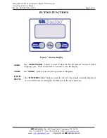
Page 8: ...struments com Copyright 2016 SInstruments Inc MODE ZERO HOLD RECAL L BUTTON FUNCTIONS The ZERO WEIGH button is used to clear the Recall memory and start a new weighing cycle Press and hold for 3 seconds to zero the display The MODE button is used to select pounds or kilograms The HOLD RECALL button is used to lock in the weight currently displayed or to recall the last saved weight if nothing is o...

Page 9: ...ay 0 0 when system is ready for weighing UNIT Press the MODE button to toggle between pounds or kilograms The system will remain in the same mode as last used unless manually changed WEIGH The WEIGH button is used to clear the Recall memory and start a new weighing cycle HOLD RECALL The HOLD RECALL button is used to lock in and store the weight currently displayed in system memory With no weight o...

Page 10: ... REASON CORRECTIVE ACTION Display reads LOW Ensure scale is on a level surface Check to make sure all six feet are touching ground and ensure that nothing is touching bottom or sides of platform For additional information or assistance phone our Service Hotline 1 800 654 6360 or e mail sri srinstruments com CALIBRATION TOLERANCE TABLE LOW LIMIT APPLIED LOAD HIGH LIMIT 99 8 100 0 100 2 199 6 200 0 ...

Page 11: ...struments Inc s part and it neither assumes nor authorizes any other person to assume for SR Instruments Inc any other liabilities in connection with the sale of said articles In no event shall SR Instruments Inc be liable for any subsequent or special damages Any misuse improper installation or tampering shall void this warranty DAMAGED SHIPMENTS Title passes to purchaser upon delivery to Transpo...

Page 12: ... Manual Part No MAN947IFS_160129 Page 12 of 12 SInstruments Inc 600 Young Street Tonawanda NY 14150 Tel 716 693 5977 Fax 716 693 5854 URL www srscales com email sri srinstruments com Copyright 2016 SInstruments Inc S By SInstruments Inc Precision Technology in Perfect Balance ...

Reviews: