8.
Set reference position: by checking this box you can manually insert the position of the base station. Please note that in this case,
GeoTagZ will not use the offset in the RINEX file so any offset between the antenna reference point (ARP) and marker (see below)
should be inserted manually in field 9. GeoTagZ will however still use the antenna type in the RINEX file.
When the ’Set reference position’ box is not checked, GeoTagZ will:
in the case of RINEX files, use the position in the RINEX header
in the case of SBF files, the static position in the SBF file will be used or
when not configured as static, a position similar to the real-time ‘auto’ setting will be used as the base station position. In this case,
it is advisable to manually enter the base station position to ensure repeatability.
9.
Reference Antenna Type: used to select the type of antenna used by the base station receiver which allows GeoTagZ to take the
phase center offset of the selected antenna into account. By selecting Offset, the East, North and Up offset between the antenna
reference point (ARP) and the position marker can be configured. When these boxes are not checked, GeoTagZ will use the antenna
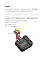
information contained in the selected reference file. The image below shows a schematic of the reference antenna setup.
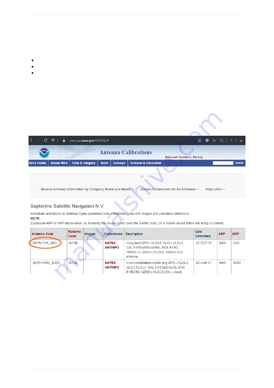
The calibration file for the recommended Altus NR3 base station will be available in the next release of GeoTagz. In the meantime, the
NGS (National Geodetic Society) provides specific calibrations for antenna types including Septentrio and other models. The Atlus
NR3 file (ANTINFO) can be found
by searching 'SEPALTUS_NR3'.
10.
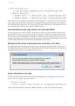
Output: this field contains the information written to the log file (geotagz.log). In this example, although there were an excess of
events, GeoTagZ was still able to correctly assign the 143 photographs to their correct event. All the photographs were geotagged with
the cm-level positioning.
Reference station antenna mounting.
PPK Tagging
121
Summary of Contents for Lynx VTOL
Page 6: ...Package Contents Package Contents 6...
Page 18: ...3 Right click on the USB Serial Port and select properties Getting Started 18...
Page 19: ...4 Swap to the Port Settings tab and select Advance Getting Started 19...
Page 86: ...Landing 86...
Page 87: ...Payloads Standard Mapping Payload Multispectral Mapping Payload Custom Payloads Payloads 87...
Page 94: ...Standard Mapping Payload 94...
Page 108: ...Mounting Custom Payloads 108...
Page 110: ...Post Processing Geo Tagging PPK Tagging Base Station Reference Stations Post Processing 110...
Page 114: ...Geo Tagging 114...
Page 130: ...Battery Charging Charging Storage Battery Management 130...
Page 136: ...Second Battery Start Charging 136...
Page 143: ...Second Battery Start Storage 143...
Page 149: ...Replacing the Main Propeller 149...
Page 167: ...Getting Logs 167...
Page 171: ...2019 02 11 Ensure the landing checklist matches the GCS landing checklist Manual Changelog 171...


