background image

Series WTH 

Page 1 

 LT105 Feb. 2019  

Installation, Operation and Service Instructions 


INFRARED 

HEATERS


SERIES  

WTH 

Single Stage 

COMMERCIAL HEATER 


WARNING


FOR YOUR SAFETY


Improper installation, adjustment, alteration, service 
or maintenance can cause property damage, injury 
or death. Read the installation, operation and 
maintenance instructions thoroughly before 
installing or servicing this equipment. 


Do not store or use flammable vapors and liquids in the 
vicinity of this or any other appliance. 
If you smell gas: 
1. Open windows 
2. Don’t touch electrical switches 
3. Extinguish any open flame 
4. Immediately call your gas supplier 


OWNER


INSTALLER


Retain this Manual & ensure available for Service. 

Improper installation, adjustment, alteration, service 
or maintenance can cause injury, death or property 
damage.  

Read the installation, operation and service 
instructions thoroughly before installing or servicing 
this equipment. 


Provide  Manual  to  Owner  upon  completion  of 
installation! 

Read  and  thoroughly  understand  these  Instructions 
before attempting any installation 


Canada: 

563 Barton Street, Stoney Creek, Ontario L8E 5S1


USA:  

315 N Madison Street, Fortville, IN 46040


www.superiorradiant.com 

Summary of Contents for WTH Series

Page 1: ...ce If you smell gas 1 Open windows 2 Don t touch electrical switches 3 Extinguish any open flame 4 Immediately call your gas supplier OWNER INSTALLER Retain this Manual ensure available for Service Im...

Page 2: ...PLOSIONS HAZARD This heater is equipped with an automatic ignition device Do not attempt to light the burner by hand Failure to comply could result in a serious fire and personal injury hazard CAUTION...

Page 3: ...ELD REFLECTOR INSTALLATION 22 INSTALLATION PREMIUM HEAT EXCHANGER 23 INSTALLATION SEQUENCE 23 HANGERS INSTALLATION 23 TUBE INSTALLATION 25 HEATER AND BAFFLE INSTALLATION 27 REFLECTOR INSTALLATION 29 E...

Page 4: ...l building codes before proceeding Only personnel who have been trained and understand all applicable codes should undertake the installation SRP Representatives are Factory Certified in the service a...

Page 5: ...must comply with all local requirements Venting Refer to the National Fuel Gas Code ANSI Z223 1 NFPA 54 in the USA and CSA B149 1 and B149 2 Installation Codes in Canada for proper location sizing an...

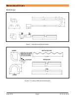
Page 6: ...Series WTH Page 6 LT105 Feb 2019 Dimensional Charts Heat Exchanger Figure 1 Overall Dimensional Information Figure 2 Component Dimensional Information...

Page 7: ...nless steel The following Special Configurations are also approved 80 000 BTU Hr 50 heat exchanger with no baffle or 6 aluminized baffle 100 000 BTU Hr 50 heat exchanger with no baffle or 6 aluminized...

Page 8: ...d surfaces and other materials which maybe damaged by radiant or convective heat Combustible materials are considered to be wood compressed paper plant fibres plastics Plexiglas or other materials cap...

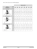
Page 9: ...71 180 33 84 4 10 36 91 74 188 36 91 6 15 40 102 78 198 40 102 6 15 44 46 80 203 44 46 45 Reflector Tilt A B C D 4 10 4 10 40 102 38 97 4 10 4 10 50 127 46 117 4 10 4 10 58 147 50 127 4 10 4 10 67 170...

Page 10: ...0 102 6 15 45 114 82 208 44 112 U Tube Opposite 45 A B C D 4 10 46 117 51 129 16 41 4 10 50 127 54 137 18 46 4 10 54 137 64 163 18 46 4 10 63 160 69 175 22 56 4 10 64 163 71 180 24 61 8 20 67 170 74 1...

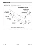
Page 11: ...tandard Heat Exchanger A general ordered sequence for installation is provided below for reference HANGERS INSTALLATION Suspension mechanism must allow for lateral tubing expansion A minimum 12 length...

Page 12: ...n the chain with Quick Links or S hooks refer to Figure 4 Figure 5 Figure 5 Typical Hanging Points Place the first flanged aluminized tube in the first two hangers Figure 6 Be sure the flange is towar...

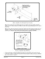
Page 13: ...hanger for support and thereafter 1 hanger section The reflector brace should be installed 6 12 from burner Also the tube weld seam must face down refer to Figure 6 for more details Figure 6 Installat...

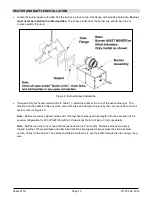
Page 14: ...oupling liners tighten each of the coupling bands progressively and alternately Tightening one band completely before the other may result in an undesirable wrinkle in the liner refer to Figure 8 Be s...

Page 15: ...on the baffle is folded over the end of the tube and clamped in place by the vent connector and vent system refer to Figure 10 Note Baffles are always placed at the end of the last heat exchanger tub...

Page 16: ...ries WTH Page 16 LT105 Feb 2019 Figure 10 Baffle Installation A general overall view of the tubes and reflector hangers are shown in Figure 11 below Figure 11 Overall view of Tubes and Reflector Hange...

Page 17: ...erlap position and one in the middle of each 10 reflector length Figure 13 shows the installation of the reflector support bracket Figure 13 Reflector Support Bracket Installation Note Reflectors shou...

Page 18: ...8 x 3 8 long screws not supplied and secure reflector to the reflector bracket at this point by tightening down 8 x 1 screws supplied with reflector brackets Figure 15 The remaining reflector overlap...

Page 19: ...Series WTH Page 19 LT105 Feb 2019 Install End Cap as shown in Figure 4 and Figure 16 Figure 16 Reflector End Cap Installation...

Page 20: ...o reduce the above clearance to combustibles distance use miter reflectors see Figure 18 and refer to Clearance to Combustibles information Figure 17 90 Elbow and U Tube Assembly Detail Elbows or U Tu...

Page 21: ...ds reflectors and or bottom shield as required Refer to Figure 18 and Figure 19 for details Side shields are 124 long Fasten one side shield per reflector with 8 x 3 8 screws Use three side shield bra...

Page 22: ...eries WTH Page 22 LT105 Feb 2019 BOTTOM SHIELD REFLECTOR INSTALLATION Bottom shields need not overlap Each 5 section is held with two support brackets see Figure 19 Figure 19 Bottom Shield Installatio...

Page 23: ...nstallation A general ordered sequence for installation is provided below for reference HANGERS INSTALLATION Suspension mechanism must allow for lateral tubing expansion A minimum 12 length welded lin...

Page 24: ...er on the chain with Quick Links refer to Figure 21 Figure 22 Figure 22 Typical Hanging Points Place the first flanged aluminized tube in the first two hangers Figure 23 Be sure the flange is toward t...

Page 25: ...n It is required that the first hanging point be 3 to 6 from the burner mounting flange and tube weld seam must face down refer to Figure 23 for more details Figure 23 Installation of First section of...

Page 26: ...ly and alternately Tightening one band completely before the other may result in an undesirable wrinkle in the liner refer to Figure 25 Be sure not to over torque the coupling Torque coupling to 15 25...

Page 27: ...hanger The small tab on the baffle is folded over the end of the tube and clamped in place by the vent connector and vent system refer to Figure 27 Note Baffles are always placed at the end of the las...

Page 28: ...ries WTH Page 28 LT105 Feb 2019 Figure 27 Baffle Installation A general overall view of the tubes and reflector hangers are shown in Figure 28 below Figure 28 Overall view of Tubes and Reflector Hange...

Page 29: ...erlap position and one in the middle of each 10 reflector length Figure 30 shows the installation of the reflector support bracket Figure 30 Reflector Support Bracket Installation Note Reflectors shou...

Page 30: ...lap together with a minimum of 2 8 x 3 8 long screws not supplied and secure reflector to the reflector bracket at this point by tightening down 8 x 1 screws supplied with reflector brackets Figure 32...

Page 31: ...Series WTH Page 31 LT105 Feb 2019 Figure 32 Reflector Supports Installation and Reflector Overlap Install End Cap as shown in Figure 33 Figure 33 Reflector End Cap Installation...

Page 32: ...thout reflectors To reduce the above clearance to combustibles distance use miter reflectors see Figure 35 and refer to Clearance to Combustibles information Figure 34 90 Elbow and U Tube Assembly Det...

Page 33: ...Series WTH Page 33 LT105 Feb 2019 MITERED REFLECTOR INSTALLATION If used install the Mitered Reflector as shown below Figure 35 Figure 35 Mitered Reflector Installation...

Page 34: ...lectors and or bottom shield as required Refer to Figure 36 and Figure 37 for details Side shields are 124 315cm long Fasten one side shield per reflector with 8 x 3 8 screws Use three side shield bra...

Page 35: ...eries WTH Page 35 LT105 Feb 2019 BOTTOM SHIELD REFLECTOR INSTALLATION Bottom shields need not overlap Each 5 section is held with two support brackets see Figure 37 Figure 37 Bottom Shield Installatio...

Page 36: ...exhanger only It can be installed either directly to the heater reflector or as part of a T Bar installation where the heater is above the ceiling structure Refer to Figure 38 and Figure 39 below for...

Page 37: ...tically IMPORTANT Maximum total vent length allowed for any model heater is 30 9m Maximum total fresh air inlet duct length allowed for any model heater is 30 9m Total of vent length plus outside air...

Page 38: ...imum Figure 40 Horizontal Venting Vertical Venting The heater operates at a negative vent pressure Refer to the National Fuel Gas Code ANSI Z223 1 NFPA 54 in the USA and CSA B149 1 Installation Codes...

Page 39: ...ers refer to ANSI Z223 1 and CSA B149 1 Use of approved thimble to pass through combustible roof material is required Additionally B type vent materials are required for stacks above the roof line Use...

Page 40: ...outside air terminal must be of an approved type and should be located at an elevation equal to or below the vent terminal elevation to prevent back venting of flue gases into the burner compartment...

Page 41: ...n the USA and CSA B149 1 and B149 2 Installation Codes in Canada Before connecting burners to the gas supply system verify that high pressure testing of the system has been completed Failure to do so...

Page 42: ...n Electric Code CSA C22 1 in Canada and must comply with all local requirements Heaters may also be controlled with a manual line switch or timer switch in place of the thermostat Refer to Figure 30 3...

Page 43: ...This allows the products of combustion to be removed from the heat exchanger to avoid nuisance condensation and increase heat exchanger life When using a line voltage thermostat and the heat requireme...

Page 44: ...turbulator flue baffle in the flue end of the heater as mentioned in the manual Is the baffle tab located at 6 o clock and bent as mentioned in the manual 10 Did you install end caps 11 Did you obser...

Page 45: ...ssure tap in gas supply system Is combination gas control gas valve or the ignition module is faulty Burner Does Not Light Is spark visible through site glass during ignition trial If no further elect...

Page 46: ...Series WTH Page 46 LT105 Feb 2019 Troubleshooting Chart...

Page 47: ...G143 HONEYWELL VALVE TRAIN REPLACEMENT KIT LPG 12 CE020 AIR SWITCH MODELS 40 000 60 000 BTU 4 CE058 TRANSFORMER CE021 AIR SWITCH MODELS 80 000 100 000 BTU 5 CE004 BLOWER FOR U T MODELS 40 000 TO 175 0...

Page 48: ...er any shipping installation or other costs incurred in the repair or replacement of the product No materials will be accepted for return without authorization This warranty will not apply if in the j...

Reviews: