Series WTH
Page 23
LT105 Feb. 2019
Installation
– Premium Heat Exchanger
Installation Sequence
Generally, there is no unique sequence for installation of the burner or heat exchanger. A review of the job site will
usually indicate a logical installation order. However, time and expense can be saved if installation is begun at the
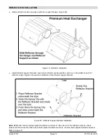
most critical dimension, watching for interference from overhead doors, cranes, auto lifts etc. Figure 20 provides a
general overview of the components utilized in the installation, as well as their general relationship.
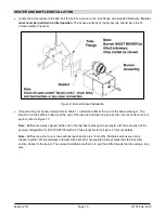
Figure 20: General Overview of Installation
A general ordered sequence for installation is provided below for reference.
HANGERS INSTALLATION
Suspension mechanism must allow for lateral tubing expansion. A minimum 12" length welded link chain with a
working load limit of at least 200 lbs. is recommended (refer to Figure 21 for more details). SRP recommends
and make available “quick links” for connecting chain. If any open ended turnbuckles are used, the open ends
must be closed to avoid unhooking chain with inadvertent contact.
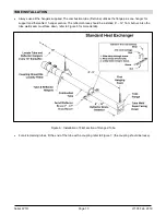
Locate hanging chain at predetermined suspension points in the structure. It is required that the first 2 hangers
be about 8' to 9' away. Thereafter, 10' apart on average is acceptable for the remainder of the heat exchanger.
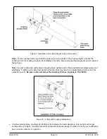
At no time should hangers be more than 12' apart, (see Figure 22).

