18
2 Operation
2.1
Functional Overview
Optical choppers provide an economical and easy‑to‑use method for in‑
troducing a square‑ or rectangular‑wave amplitude modulation to an
optical signal. Well‑defined signal modulation permits synchronous de‑
tection (e.g. with a lock‑in amplifier) to identify weak signals in the pres‑
ence of noise and large background.
The SR542 provides optical modulation from 0.4 Hz to 20 kHz. By em‑
ploying a brushless, slotless DC motor, mechanical vibrations and phase
jitter are dramatically reduced. A brushless motor also extends the op‑
erating life of the chopper, as compared to brushed motor designs in
which the commutation contacts can wear out.
Key features of the SR542 include:
• wide range of chopping frequencies
• ±20 ppm frequency accuracy
• phase locking to external signals (e.g. provided by lock‑in ampli‑
fier, function generator, or another chopper)
• frequency control by external DC voltage (VCO mode)
• phase locking to AC line
• low phase jitter
• long‑life brushless motor
• single and dual beam experiments
• sum and difference frequency reference outputs
• harmonic, sub‑harmonic, and fractional harmonic phase locking
• adjustable and reproducible phase, including settable relative
phase, with
0.01°
resolution
• shutter mode (fixed position)
• full remote operation by USB interface
• non‑volatile memory for nine (9) user‑defined instrument config‑
urations
2.1.1
Chopper Control Loop
Figure 2.1 depicts the control loop responsible for driving the chopper
motor at the appropriate frequency and phase to achieve lock with the
chosen reference. The user selects from four frequency references (the
Source
): Internal Freq, VCO Input, AC Line, and Ext Sync.
The selected source determines the frequency of the Source Clock. The
Source Clock frequency is set directly in Internal Freq and VCO Input
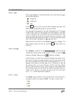
modes by the
Int Freq
setting or DC voltage supplied to
VCO Input
, re‑
spectively. For AC Line or Ext Sync modes, the Source Phase‑Locked
SR542 Precision Optical Chopper


