2.1 Functional Overview
19
Loop (PLL) uses PID control to minimize the phase difference
Δ𝜙
be‑
tween the input signal and the Source Clock. The Source Clock is made
available as a 50% duty cycle 5 V logic signal at the
Source Out
BNC on
the rear panel.
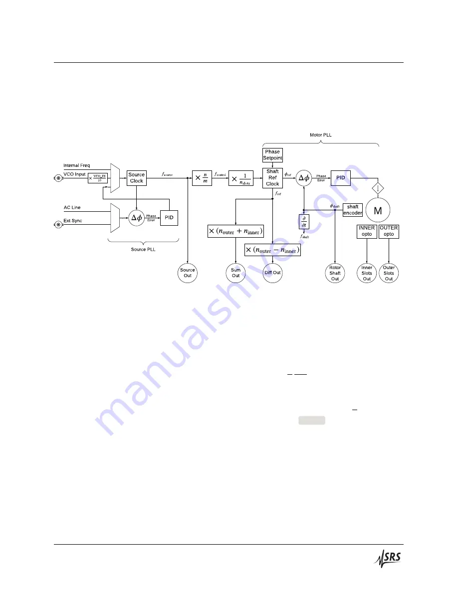
Figure 2.1:
Block diagram of the chopper control loop. Signal inputs (Ext Sync and VCO Input) are shown at the
top left. Signal outputs are shown along the bottom.
From the Source Clock, several other clocks are derived. The first of
these—the Shaft Reference Clock—provides a reference signal to the
Motor PLL, which uses another PID controller to calculate the motor
drive current necessary to lock the chopper. Specifically, the Motor PLL
will work to bring
𝑓
shaft
= 𝑓
source
× (
𝑛
𝑚
1
𝑛
slots
)
and
𝜙
shaft
= 𝜙
setpoint
. An
optical encoder affixed to the rear shaft of the chopper motor is used to
measure
𝜙
shaft
and
𝑓
shaft
.
Also available to the user via remote query is
(𝑓
source
×
𝑛
𝑚
)
. This is the
target control frequency for the selected
Control
track (see
Finally, when used with a dual‑frequency chopper blade, the SR542 syn‑
thesizes square wave reference outputs at
(𝑓
OUTER
+ 𝑓
INNER
)
(sum) and
(𝑓
OUTER
− 𝑓
INNER
)
(difference). These references can be used for non‑
linear mixing experiments (e.g. a non‑linear sample excited simultane‑
ously at
𝑓
INNER
and
𝑓
OUTER
will respond at sum and difference frequen‑
cies). For a detailed example, see Section 4.3.
Other available outputs on the rear panel are produced by optical sen‑
sors on the chopper head itself:
Inner Slots Ref Out
and
Outer Slots Ref
Out
are generated by slotted opto‑interrutpers at the base of the chopper
head, and
Rotor Shaft Ref Out
is generated by the shaft encoder.
SR542 Precision Optical Chopper


