28
2 Operation
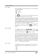
Regardless of operating mode the remote query
will always re‑
spond with internally stored phase in the range
𝑛
slots
×
(‑360
°
, +360
°
).
2.2.3 Configuration
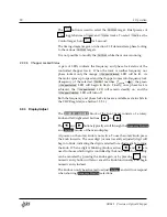
The
CONFIGURATION
block provides a simplified block diagram of the
chopper control loop (See Section 2.1.1 for detailed discussion). This
block indicates the frequency
Source
, the edge or trigger slope, the fre‑
quency
Multiplier
, and the
Control
track to be phase locked.
2.2.3.1
Frequency Source
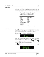
The frequency source to which the Source Clock is phase‑locked can be
selected from:
Internal Freq
VCO Input
AC Line
Ext Sync
The selected source is indicated by the
Source
LEDs. The
Source
→
Int
button
is used to select the frequency source. Single button presses scroll top‑
to‑bottom through the available sources.
For all sources other than
Internal Freq
, a long press (
∼
1 s) of
Source
→
Int
will
Jump to Int
copy the most‑recently estimated Source frequency to the
Int Freq
set‑
ting, and the
Source
will jump to
Internal Freq
. The Source Clock will
then proceed at that stable, fixed frequency.
The
Jump to Int
feature could be useful to diagnose a noisy Ext Sync
signal which the SR542 has difficulty tracking with its Source PLL.
With the exception of the
Jump to Int
function, it is not possible to modify
the
Source
while the motor is on.
When
AC Line
or
Ext Sync
are the selected source, the
Locked
LED in‑
dicates that the control unit has successfully phase locked to the AC Line
signal or the signal provided at the
Ext Sync Input
on the rear panel. If
the
Locked
indicator is not stable, the external signal may be too noisy,
small, or out of range.
Locked
indication is independent of the chopper
motor, and
does not
imply that the chopper blade has been successfully
locked to the external signal (see Section 2.2.3.5: Chopper Locked Sta‑
tus).
If
Ext Sync
is selected as the source and the signal at the
Ext Sync Input
is not within the valid range of input frequencies, the
Ext Sync
source
LED will flash.
SR542 Precision Optical Chopper


