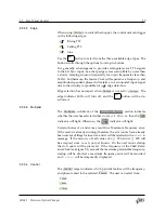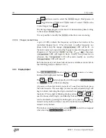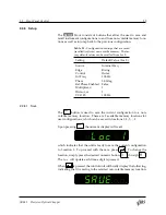
36
2 Operation
The BNC connections are organized into three categories:
1.
Source
— inputs and outputs for the reference to which the chop‑
per is phase locked.
2.
Reference Outputs
— TTL logic signals from sensors on the chop‑
per head.
3.
Synthesized Outputs
— TTL square wave signals with frequen‑
cies determined by the sum and difference frequencies of the inner
and outer tracks. Waveforms are synthesized by the controller.
2.3.1
Source Inputs and Output
2.3.1.1
VCO Input
The VCO Input BNC connection accepts a 0 to +10 V
dc
input. When
the control unit is configured to use the VCO Input as the source, the
DC voltage present at this input is low‑pass filtered, digitized, and di‑
vided by 10 V to provide a scale factor between 0 and 1. This scale factor,
multiplied by the user setting
VCO FS
determines the Source frequency.
Mathematically, the DC voltage
𝑉
DC
determines the source frequency
(in Hz) as
𝑓
source
= (
𝑉
DC
10
V
) ×
VCO_FS
where VCO_FS is set on the Front Panel using the
VCO FS
setting (see
Section 2.2.2.2) or using the remote command
.
2.3.1.2
Ext Sync Input
The Ext Sync Input accepts TTL or sinusoidal inputs. The TTL edge
threshold is set to +1 V, and should be driven with a waveform of at
least 2 V amplitude. When the sine input is selected via the Sine trigger
edge, the input is AC‑coupled and is unreliable for frequencies <1 Hz.
2.3.1.3
Source Output
The BNC connection for Source Output provides a +5 V square wave
signal at the frequency of the selected
.
SR542 Precision Optical Chopper


