SS-15 BRI (ISDN 2 GSM) USER MANUAL
DOC. NO: SS-15-14 (REV. 01)
Page 11 of 26
BRI interface or its antennas too close to such appliances, their operation could
be affected.
Note1: The antennas of the SS-15 BRI (ISDN 2 GSM) interface send out RF
energy so they should NOT be placed very close to people. Since the GSM
interface transmits for longer periods of time, being used by several people
(most of the calls of local subscribers are routed through it) the radiation will be
accordingly higher than for a cell-phone used only infrequently, by a single
person.
Note2: Remember to connect the antennas before powering up the SS-15 BRI,
to avoid damage to the transmitters of the GSM modules.
4.6
JUMPER SETTINGS
The SS-15 BRI (ISDN 2 GSM) features several jumpers located on the printed
circuit board, inside the enclosure. These jumpers control functions seldom
needed, therefore, under normal operation these settings do not need to be
changed.
4.6.1.
Bootloader enable
Use
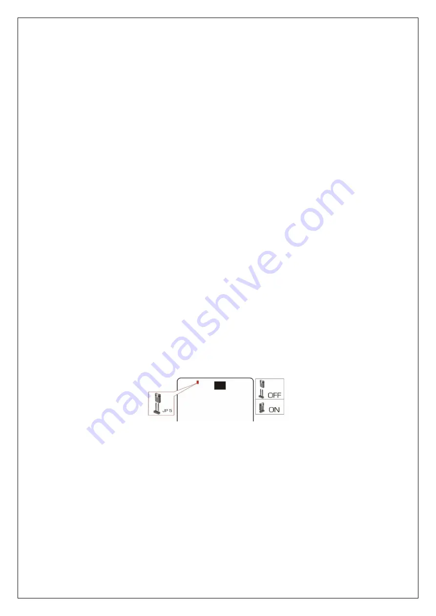
If an abnormal interruption occurred in the loading of an image file, use the JP5
jumper.
To fix this problem, set the jumper on the JP5 pins to force the bootloader to
start. In order to load a new image file please refer to the isdncfg OAM manual.
Remember to take the jumper off pins JP5 before resuming normal operation
of the ISDN 2 GSM equipment.
Location
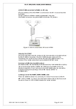
Figure 6. JP5 jumper location
Jumper JP5 is located near the top left corner of the printed circuit board of the
SS-15 BRI. Immediately to the right of JP5 the connector for the external
antenna can be seen. JP5 is alone (no other jumpers close to it) and it is in a
vertical position.
4.6.2.
Terminal resistors
Use
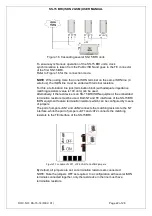
These pairs of jumpers (JAN1 and JAN2 for the NT interface, JAT1 and JAT2 for
the TE interface) configure the impedance matching (termination) resistors for
the respective interfaces.
By default, these jumpers are ON so the terminal resistors are connected. The
jumpers should be taken OFF if terminal resistors are not required.


