SS-15 BRI (ISDN 2 GSM) USER MANUAL
DOC. NO: SS-15-14 (REV. 01)
Page 22 of 26
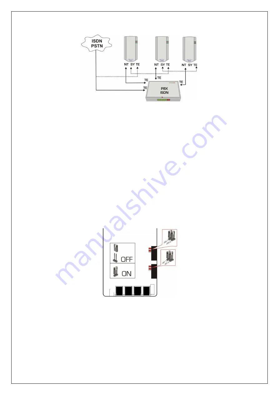
Figure 16. Cascading several SS-15 BRI units
To ensure synchronous operation of the SS-15 BRI units, clock
synchronization is taken from the Public ISDN and goes to the TE connector
of the first SS-15 BRI.
Refer to Figure 16 for the connection mode.
NOTE: When using more than one ISDN terminal on the same ISDN line (4
wire bus), the ISDN line must be ended with terminal resistors.
For this, a termination line jack (termination block) with adequate impedance
matching resistors (value is 100 ohm) can be used.
Alternatively, if the last device is an SS-15 BRI ISDN equipment, the embedded
termination resistors must be used. Both NT and TE interfaces of the SS-15 BRI
ISDN equipment feature termination
resistors which can be configured by means
of jumpers.
The pair of jumpers JAN1 and JAN2 connects the matching resistors to the NT
interface, while the pair of jumpers JAT1 and JAT2 connects the matching
resistors to the TE interface of the SS-15 BRI.
Figure 17. Location of JAT1, JAT2, JAN1 and JAN2 jumpers
By default, all jumpers are set, so termination resistors are connected.
NOTE: Take the jumpers OFF as required. In a configuration with several ISDN
terminals connected together, only the last device in the line must have
termination resistors
.


