background image

4A-7

CHANGED BY

EFFECTIVE DATE

AFFECTED VIN

FRONT AXLE

REXTON SM - 2004.4

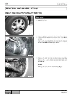
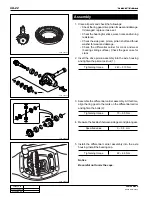
4. Unscrew two bolts (arrows) and remove the brake caliper

assembly.

Notice

Be careful not to damage the brake oil hose.

Y220_04A007

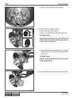
5. Vehicle with part time transfer case only.

1) Remove the hub mounting bolt and washer, and

remove the hub cover.

2) Remove the retainer ring and outer shim between

hub body and drive shaft, and remove the locking
hub.

3) Remove the locking hub from steering knuckle.

Y220_04A008

Y220_04A009

Y220_04A010

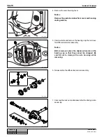
Installation Notice

• Adjust the clearance between snap ring and hub

cover with appropriate shims (shim thickness: 0.
2, 0.3, 0.5 and 1.0 mm) so that it is below 0.2 mm.

• Be careful not to damage the O-ring in locking

hub.

Summary of Contents for 2004 Rexton 2.7XDi

Page 1: ...e air flow chart DI0A 15 INTAKE SYSTEM DI0A 16 Exhaust air flow chart DI0A 17 LUBRICATION SYSTEM DI0A 18 COOLING SYSTEM DI0A 19 Coolant flow chart DI0A 20 FUEL SYSTEM DI0A 21 Fuel supply system DI0A 22 GENERAL SPECIFICATIONS DI0A 23 Vehicle specifications DI0A 23 Maintenance DI0A 26 VEHICLE IDENTIFICATION DI0A 28 HOW TO USE AND MAINTAIN WORKSHOP MANUAL DI0A 30 Consists of workshop manual DI0A 30 M...

Page 2: ...pply high pressurized fuel This increases the pressure to combustion chamber over 250 bar and may cause fatal damage to engine You can compare the thickness of injector nozzle hole and hair as shown in below figure left side The right side figure shows the clearance between internal operating elements Cleanness of DI Engine Fuel System and Service Procedures The core elements of fuel system has ve...

Page 3: ...d vehicle appearance on the wiring harnesses and connectors in engine compartment Perform the diagnosis proceee with Scan i refer to DIAGNOSIS section in this manual Locate the fault If the cause is from fuel system from priming pump to injector including return line follow the step 1 through step 3 above 5 If the problem is from HP pump fuel supply line or injector prepare the clean special tools...

Page 4: ... and fuel rail and between fuel rail and each injector should be replaced with new ones The pipes should be tightened to specified tightening torques during installation Over or under torques out of specified range may cause damages and leaks at connections Once installed the pipes have been deformed according to the force during installtion therefore they are not reusable The copper washer on inj...

Page 5: ...replacing the high pressure pump 9 To supply the fuel to transfer line of HP pump press the priming pump until it becomes hard 10 Check the installed components again and connect the negative battery cable Start the engine and check the operating status 11 With Scan i check if there are current faults and erase the history faults Note For details refer to DI10 Diagnosis teable Y220_0A040 Y220_0A04...

Page 6: ...ausing difficult starting finally Oil companies supply summer fuel and winter fuel by differentiating mixing ratio of kerosene and other elements by region and season However above phenomenon can be happened if stations have poor facilities or sell improper fuel for the season In case of DI engine purity of fuel is very important factor to keep internal preciseness of HP pump and injector Accordin...

Page 7: ...Air conditioner compressor 3 Power steering pump pulley 4 Idle pulley 5 Water pump pulley 6 Alternator 7 Cooling fan pulley viscos clutch 8 Aut tensioner pulley 9 Auto tensioner 10 Poly groove belt 11 Cam position sensor 12 Drive plate M T DMF 13 Oil filter housing 14 Vacuum pump 15 Crank position sensor 16 EGR valve 17 Power steering pump 18 EGR center pipe ...

Page 8: ...04 4 Top view Y220_0A002 19 Cylinder head cover 20 Intake manifold 21 Water outlet port 22 Common rail 23 Fuel pressure sensor 24 Fuel pipe 25 Injector 26 Fuel return line 27 Oil filler cap 28 Glow plug 29 Booster pressure sensor 30 Oil separator 31 Oil dipstic 32 EGR center pipe ...

Page 9: ...2004 4 Right side view Left side view Y220_0A003 33 Cylinder head 34 Cylinder block 35 Oil pan 36 Drain plug 37 Turbocharger 38 EGR RH pipe 39 Oil separator 40 Oil dipstic 41 HP pump 42 Turbocharger vacuum modulator 43 EGR valve vacuum modulator 44 EGR valve 45 Exhaust manifold ...

Page 10: ... INFORMATION DI ENG SM 2004 4 HFM sensor intake air temperature sensor Pre heating time relay Main relay ECU barometric sensor Cam position sensor Fuel filter water detection sensor Accelerator pedal sensor ECU RELATED COMPONENTS ENGINE CONTROLS Y220_0A004 ...

Page 11: ...IN GENERALINFORMATION DI ENG SM 2004 4 Common rail Fuel pressure sensor Booster pressure sensor Camshaft position sensor Knock sensor 2 Crankshaft position sensor Injector HP pump Glow plug Coolant temperature sensor ENGINE AND SENSORS Y220_0A005 ...

Page 12: ...3 CHANGED BY EFFECTIVE DATE AFFECTED VIN GENERAL INFORMATION DI ENG SM 2004 4 Y220_0A006 ELECTRICAL COMPONENTS AND PRE HEATING SYSTEM Glow plug Pre heating time relay Battery Fuse box Alternator Starter motor ...

Page 13: ...ED BY EFFECTIVE DATE AFFECTED VIN GENERALINFORMATION DI ENG SM 2004 4 Air cleaner assembly Intake duct hose HFM sensor Intake manifold Intake outlet hose Turbocharger Intercooler Inlet hose Y220_0A007 INTAKE SYSTEM ...

Page 14: ...ECTED VIN GENERAL INFORMATION DI ENG SM 2004 4 Intake valve in combustion chamber Intake manifold Intake hose inner Intake hose outlet Intercooler HFM sensor Turbo charger compressor Air cleaner side Engine INTAKE AIR FLOW CHART Y220_0A008 ...

Page 15: ...DI0A 16 CHANGED BY EFFECTIVE DATE AFFECTED VIN GENERALINFORMATION DI ENG SM 2004 4 Muffler Exhaust manifold EGR valve Vacuum modulator Turbocharger Catalytic converter EGR pipe Y220_0A009 INTAKE SYSTEM ...

Page 16: ... SM 2004 4 Exhaust pipe Catalytic converter Muffler Ambient air Exhaust gas EGR vacuum modulator To turbocharger booster Turbocharger booster vacuum modulator EGR valve EGR pipe Turbocharger booster Turbocharger turbine side Exhaust manifold EXHAUST AIR FLOW CHART Y220_0A010 ...

Page 17: ...TIVE DATE AFFECTED VIN GENERALINFORMATION DI ENG SM 2004 4 Oil dipstic PCV valve Engine oil filter housing Engine oil pump Oil pan Engine oil cooler Engine oil pressure switch Cylinder head cover Y220_0A011 LUBRICATION SYSTEM ...

Page 18: ...DI0A 19 CHANGED BY EFFECTIVE DATE AFFECTED VIN GENERAL INFORMATION DI ENG SM 2004 4 Y220_0A013 COOLING SYSTEM Coolant reservoir Radiator assembly Cooling fan and fan clutch Water pump ...

Page 19: ...TIVE DATE AFFECTED VIN GENERALINFORMATION DI ENG SM 2004 4 Coolant reservoir Thermostat Heater Intake manifold Coolant outlet port Outlet hose Radiator Cooling fan Inner hose Water pump Y220_0A014 COOLANT FLOW CHART Oil cooler ...

Page 20: ...DI0A 21 CHANGED BY EFFECTIVE DATE AFFECTED VIN GENERAL INFORMATION DI ENG SM 2004 4 Fuel return hose Fuel pressure pipe Common rail Fuel filter Injector HP pump Priming pump Y220_0A015 FUEL SYSTEM ...

Page 21: ...etects intake air volume and sends the signals to ECU Especially the engine ECU controls the air fuel ratio by recognizing instant air volume changes from air flow sensor to decrease the emissions EGR valve control Furthermore ECU uses signals from coolant temperature sensor and air temperature sensor booster pressure sensor and barometric sensor as compensa tion signal to respond to injection sta...

Page 22: ...DI0A 23 CHANGED BY EFFECTIVE DATE AFFECTED VIN GENERAL INFORMATION DI ENG SM 2004 4 VEHICLE SPECIFICATIONS Vehicle Dimension Y220_0A017 mm GENERAL SPECIFICATIONS ...

Page 23: ...all length mm Overall width mm Overall height mm Gross vehicle weight kg Curb weight kg Min turning radius m Ground clearance mm Fuel Fuel tank capacity Model No of cyl Compression ratio Total displacement Camshaft arrangement Max power Max torque Injection timing Idle speed Cooling system Coolant capacity Lubrication Max oil capacity Turbo charger and cooling type Type Model Type Systems Items Di...

Page 24: ...e Battery type Capacity V AH Starter capacity V kW Alternator capacity V A Diesel Part time Planetary gear type 1 000 1 2 483 1 Hydraulic A T Torque converter Dry single diaphragm type A T 3 elements 1 stage 2 phases Rack and pinion 36 17 32 40 Ball joint type Build up type Semi floating type Build up type Tandem type Vacuum booster Disc Drum Disc Cable type internal expansion Wishbone Coil spring...

Page 25: ...km Replace at every 10 000 km Replace at every 60 000 km Engine oil and oil filter DI diesel engine IDI diesel engine Coolant Brake pipe and hose Brake pad shoe and disc More frequent maintenance is required if the vehicle is operated under severe condition Severe conditions Frequent low speed operation as in stop and go traffic When most trips are less than 6 km in winter less than 16 km Driving ...

Page 26: ... III CASTROL TQ 95 SHELL or FUCHS ATF 3353 ATF DEXRON II III ATF S 4 TOTAL FLUID ATX SAE 80W 90 API GL 5 SHELL Retinax A grade ALVANIA EP 2 Engine coolant Antifreeze and soft water mixed Manual transmission oil Brake Clutch fluid Level must be maintained between MAX MIN level Power steering fluid Automatic transmission fluid Transfer case fluid 4WD 3 6 L 2WD 3 4 L Properly 1 1 L 4 speed 9 5 L 5 sp...

Page 27: ...P Rexton O Body Type O 5 door A Trim Level A Standard B Deluxe C Super deluxe 1 Restraint System 0 No seatbelts 1 3 point seatbelts 2 2 point seatbelt 9 Engine Type 9 3199cc In line 6 cylinders Gasoline E32 D 2874cc Il line 5 cylinders Diesel S Check Digit S All area except North America 1 Model Year 1 2001 2 2002 3 2003 P Plant Code P Pyungtaek plant 122357 Production serial number 2 Certificatio...

Page 28: ...cylinder block in exhaust manifold side 4 Manual Transmission Number The transmission label is affixed on the upper area of clutch housing Y220_0A020 5 Automatic Transmission Number The transmisson label is affixed on the right area of transmis sion housing Y220_0A021 6 Transfer Case Number The transfer case label is affixed on the transfer case housing Y220_0A022 ...

Page 29: ...roviding simple removal installation information but focused on to describe much more functions roles and principles of system Every automotive term like part name on the manual is the same in parts catalog technical bulletin and drawings to avoid confusion among them Consists of Small Group 1 Contents In small group included subjects and detailed subjects are described in 2 General In the general...

Page 30: ... may be hot enough to burn you So inspect related locations when they cooled down enough If engine is running keep your clothing tools hair and hands away from moving parts Even when the ignition key is turned off and positioned to LOCK electrical fan can be operated while working on near around electrical fan or radiator grille if air conditioner or coolant temperature rises Every oil can cause s...

Page 31: ...in this manual and clean each component with engine oil and then coat with oil before installation While removing engine drain engine oil coolant and fuel in fuel system to prevent leakage During service work of removal installation be sure to check each connected portions to engine not to make interference Electrical equipment Electrical equipment should be handled more carefully Currently the en...

Page 32: ...ft up the vehicle and then support with chassis stand before service work 3 Before service work be sure to disconnect battery negative terminal to prevent damages by bad wire and short 4 If service from interior of the vehicle use protection cover to prevent damage and contamination of seat and floor 5 Brake fluid and anti freeze can damage painted surface of body So carefully handle them during s...

Page 33: ...y of oil 13 Coat oil or grease on the driving and sliding surfaces before installing parts 14 Use sealer or gasket to prevent leakage if necessary 15 Damaged or not never reuse removed gasket Replace with new and cautious on installing directions 16 Tighten every bolt and nut with specified torque 17 When service work is completed check finally whether the work is performed properly or the problem...

Page 34: ...e sure to disconnect battery negative terminal during every service work Before disconnecting battery negative terminal turn off ignition key 2 Replace with specified capacity of fuse if there is bad blown or short circuited fuse If use electrical wire or steel wire other than fuse there can be damages on the various electrical systems If replaced with over capacity fuse there can be damages on th...

Page 35: ...post lift securely and block the front and rear of each tire not to move during working Notice During lifting be sure to check whether vehicle is empty Board on lift connection device installed in front of vehicle should be positioned in front of sill locating under the front door Install lift connecting device on the edge of front and rear of board on lift Warning Be sure to use attachment during...

Page 36: ... 1 600 2 200 3 000 3 900 3 800 7T 12 27 53 91 210 430 420 770 730 1 200 1 900 2 700 3 700 5 000 6 500 6 300 Tightening Torque kg cm 9T 17 40 77 130 310 620 600 1 100 1 000 1 900 2 700 3 800 5 300 7 200 9 400 9 100 1 Metric bolt strength is embossed on the head of each bolt The strength of bolt can be classified as 4T 7T 8 8T 10 9T 11T and 12 9T in general 2 Observe standard tightening torque durin...

Page 37: ...27DT engine DI01 3 Engine performance curve DI01 8 General diagnosis DI01 10 DIAGNOSTIC INFORMATION AND PROCEDURE DI01 15 Oil leak diagnosis DI01 15 Compression pressure test DI01 16 Cylinder pressure leakage test DI01 18 Tightening torque DI01 19 REMOVALAND INSTALLATION DI01 22 Engine mounting DI01 22 DISASSEMBLYAND REASSEMBLY DI01 32 Components and special tools DI01 32 ...

Page 38: ...ering pump 10 Priming pump Y220_01001 STRUCTURE AND FUNCTION DESCRIPTIONS D27DT ENGINE Major Components in Engine and Engine Compartment The advanced electronically controlled D27DT engine that has high pressure fuel system has been introduced to this vehicle It satisfies the strict emission regulation and provides improved output and maximum torque 11 EGR valve 12 Air cleaner assembly 13 Turbo ch...

Page 39: ...ssor 3 Power steering pump pulley 4 Idle pulley 5 Coolant pump pulley 6 Alternator Front View Rear View 7 Viscos fan clutch 8 Auto tensioner pulley 9 Auto tensioner 10 Poly grooved belt 11 Cam position sensor 12 Drive plate MT DMF 13 Oil filter 14 Vacuum pump 15 Crank position sensor 16 EGR valve 17 Power steering pump 18 EGR to center pipe Y220_01002 ...

Page 40: ... View 19 Cylinder head cover 20 Intake manifold 21 Water outlet port 22 Common rail 23 Fuel pressure sensor 24 Fuel pipe 25 Injector 26 Fuel return line 27 Oil filler cap 28 Glow plug 29 Booster pressure sensor 30 PCV valve and oil separator 31 Oil dipstick 32 EGR LH pipe Y220_01003 ...

Page 41: ...w Left Side View 33 Cylinder head 34 Cylinder block 35 Oil pan 36 Drain plug 37 Turbo charger 38 EGR RH pipe 39 PCV valve and oil separator 40 Oil dipstick 41 High pressure pump 42 Turbo charger booster vacuum modulator 43 EGR valve vacuum modulator 44 EGR valve 45 Exhaust manifold Y220_01004 ...

Page 42: ...000 km 80 SAE 10W40 5W40 MB Sheet 229 1 229 3 approved oil Forced delivery Full flow filter element type 6 8 8 3 Water cooling type Belt operated typr 85 WAX pellet type 11 5 Idle speed Valve Camshaft Fuel system Lubrication system Cooling system Displacement cc Compression ratio Maximum output ps rpm Maximum torque kg m rpm Intake Exhaust For Manual Transmission For Automatic Transmission Opening...

Page 43: ...DI01 8 CHANGED BY EFFECTIVE DATE AFFECTED VIN ENGINEASSEMBLY DI ENG SM 2004 4 ENGINE PERFORMANCE CURVE Output and Torque Y220_00025 Torque Nm Output PS Speed rpm ...

Page 44: ...DI01 9 CHANGED BY EFFECTIVE DATE AFFECTED VIN ENGINEASSEMBLY DI ENG SM 2004 4 Oil Temperature Pressure and Boost Pressure Y220_00026 Boost pressure bar Oil pressure bar Oil temperature C Speed rpm ...

Page 45: ...proper ignition timing Faulty spark plug Electric leakage or poor connection of the high tension cable Correction Replace the fuse Clean adjust the plug gap or replace Replace the cable Replace the cable or wires Adjust the ignition timing Replace the ignition coil Feed the fuel Replace the filter Clean the fuel pipe Replace the fuel pump Replace the injector Clean the fuel tank Tighten to the spe...

Page 46: ...anifold gasket Correction Clean the pipe Replace the filter Check and repair the system Clean or replace the air cleaner element Replace the gasket Repair or replace the brakes Refer to Compression Pressure Test Clean the pipe Replace the filter Replace the regulator Adjust or replace the spark plug Connect the cable correctly or replace it Adjust the ignition timing Replace the ignition coil Clea...

Page 47: ...eplace the fuel pressure regulator Adjust or replace the spark plug Connect the cable correctly or replace it Adjust the ignition timing Clean or replace the gasket Connect the hose correctly or replace it Refer to Overheat in this page Replace the spark plug Adjust the ignition timing Connect the cable correctly or replace it Clean or replace the fuel filter and the fuel pipe Replace the gasket R...

Page 48: ...il Blocking oil strainer Lowered function of the oil pump Abrasion or damage of the oil pump relief valve Correction Refer to Compression Pressure Test Repair or replace the fuel tank or the fuel pipe Adjust the ignition timing Replace the plug Connect the cable normally or replace it Repair the thermostat Repair or replace the valve Adjust the pressure of tires Tighten the plug Tighten the bolt E...

Page 49: ...aring cap bolt Excessive clearance of the crankshaft thrust bearing Low oil pressure Correction Adjust the valve clearance Replace the valve stem or the guide Replace the spring Boring the cylinder or replace the piston the ring or the cylinder Replace the bearing Tighten to the specified torque Replace the bearing Grind or replace the crankshaft journal Tighten to the specified torque Adjust or r...

Page 50: ...itoins 4 Visually inspect the suspected component You should be able to trace the leak path over the white powder surface to the source DIAGNOSTIC INFORMATION AND PROCEDURE Black Light and Dye Method A dye and light kit is available for finding leaks Refer to the manufacturer s directions when using the kit 1 Pour the specified amount of dye into the engine oil fill tube 2 Operate the vehicle norm...

Page 51: ... not allow anybody to be in front of the vehicle Specifications Y220_01005 COMPRESSION PRESSURE TEST The compression pressure test is to check the conditions of internal components piston piston ring intake and exhaust vale cylinder head gasket This test provides current engine operating status Compression ratio Test temperature Compression pressure Normal value Minimum value Permissible pressure ...

Page 52: ...arge the combustion residues in the cylinders before testing the compression pressure Apply the parking brake before cranking the engine Measuring Procedure Y220_01006 Y220_01007 Y220_01008 4 Remove the glow plugs and install the compression pressure tester into the plug hole 5 Crank the engine for approx 10 seconds by using the start motor 6 Record the test result and measure the compression pres...

Page 53: ...leak age test Permissible Pressure Leakage Notice Perform the pressure in order 1 2 3 4 5 Do not test the cylinder pressure leakage with wet type test procedure do not inject the engine oil into the combustion chamber Y220_01009 Test temperature At whole engine At valve and cylinder head gasket At piston ring at normal operating temperature 80 C Max 25 Max 10 Max 20 CYLINDER PRESSURE LEAKAGE TEST ...

Page 54: ...mperature sensor M6 x 22 M11 x 62 M9 x 52 M6 x 20 M8 x 35SOC M6 x 20 M6 x 16 M6 x 40 M6 x 60 M6 x 70 M8 x 80SOC M10 x 30 M18 x 50 M6 x 20 M6 x 35 M6 x 38 M6 x 40 M8 x 40 M14 x 1 5 8 1 M7 x 16 M8 x 25 M8 x 50 M12 x 177 M12 x 158 M8 x 60 M8 M11 x 52 M22 M14 10 1 55 5 90 10 40 5 90 10 10 1 25 2 5 10 1 10 1 10 1 10 1 10 1 25 2 5 45 5 90 10 325 33 90 10 10 1 10 1 10 1 25 2 5 25 2 5 65 5 20 2 x 90 10 25...

Page 55: ...ng fan bracket assembly Cylinder head cover M8 x 45 LOWER M12 x 90 M6 x 50 M6 x 12 M6 x 12 M8 x 32 M10 x 90 M8 x 95 M8 x 25 M8 x 60 M6 x 14 M8 x 16 M8 x 45 M8 x 130 M6 x 16 M8 x 28 M8 x 16 M6 x 16 M8 M8 M8 M8 x 22 M6 x 16 Cylinder block side M16 T C side M6 x 16 T C side M6 x 16 Cylinder block side M8 x 22 M6 x 16 M8 x 22 M6 x 16 M8 x 16 M8 M5 M6 x 20 M6 x 25 M6 x 65 M6 x 85 M6 x 35 Size Name NO 2...

Page 56: ...ring pump Piston protrusion Clearance between connecting rod and pin boss End play of crankshaft Name NO 48 49 50 51 52 53 54 55 56 57 58 59 60 61 62 63 64 NEW 0 100 0 245 mm USED 0 300 mm 10 1 0 10 1 0 10 1 0 25 2 5 25 2 5 25 2 5 25 2 5 10 1 0 180 20 10 1 0 10 1 0 0 8 0 4 0 7 1 5 10 1 0 25 2 5 25 2 5 25 2 5 25 2 5 0 765 1 055 0 05 0 31 Tightening Torque 4 3 1 1 2 1 3 5 1 5 1 1 5 2 2 2 2 5 5 Quant...

Page 57: ...re removal 2 Drain the engine oil 3 Drain the engine coolant 4 Be careful not to splash the fuel to the vehicle body It may cause a fire or vulcanization of rubber products Make sure to block the fuel related hoses before removal 1 Side Mountings Left Right 2 Transmission Mounting 3 Exhaust Manifold and Pipe 4 Cables and Connectors REMOVAL AND INSTALLATION ...

Page 58: ...he engine compartment Installaiton Notice 4 Loosen the radiator drain cock and drain the coolant Y220_01012 Y220_01013 Y220_01014 Notice If not necessary place the ignition switch at OFF position Tightening torque 12 1 2 Nm Notice 1 Be careful not to contact with coolant If contacted wash with soap and water to ensure all coolant is removed 2 Use only designated coolant 3 Open the coolant reservoi...

Page 59: ...e inlet hose 1 and the heater hose 2 under the radiator 8 Remove the coolant outlet hose over the radiator 9 Remove the radiator grille and loosen the hose clamp on the outlet port of turbo intercooler Note For the removal and installation of radiator grille refer to Cooling System section Y220_01015 Y220_01016 Y220_01017 Y220_01021 Notice Be careful not to damage the rubber hose Notice Be careful...

Page 60: ...from the turbo charger 10 Loosen the hose clamp on intake air hose of turbo charger and remove the intake air hose 11 Separate the outlet hose of oil separator from the intake air hose of turbo charger 12 Loosen the clamp on the intake air duct hose of turbo charger at the air cleaner side and separate the hose from the air cleaner housing Y220_01022 Y220_01018 Y220_01020 Y220_01023 ...

Page 61: ...tallation Notice 17 Remove the power steering inlet pipe and the outlet hose from the power steering pump 18 Remove the vacuum hose from the brake booster Installation Notice Notice Plug the openings of hoses and pump with caps not to flow out the oil Tightening torque 25 2 5 Nm Installation Notice Inlet pipe union nut 25 2 5 Nm Vacuum pipe union nut at vacuum pump side 10 Nm Y220_01024 Y220_01027...

Page 62: ...or terminal cable 19 Remove the supply inlet supply outlet and return hose from the fuel filter Y220_01030 Y220_01031 Y220_01032 Y220_01033 Notice 1 When separating the hoses from the fuel filter plug the openings with caps so that the contaminants will not get into the fuel system 2 Mark on all the hoses not to be mixed each other Notice Make sure to properly tighten the cable nuts when installin...

Page 63: ... cooler pipes Note The oil cooler pipes are connected to cylinder block at both sides and bottom area of oil with brackets Installation Notice 26 Set up the special to the cooling fan pulley and remove the cooling fan assembly To make the removal easier loosen the radiator shroud Installation Notice Y220_01034 Y220_01035 Y220_01036 Y220_01038 Cooling fan pulley bolt 10 1 0 Nm Pipe mounting bracket...

Page 64: ...ove the radiator shroud Installation Notice 28 Take off the fan belt from the engine Note 1 Insert a tool into the belt tensioner and rotate it counterclockwise to take off the fan belt 2 After installation of the fan belt pump the belt tensioner 3 to 4 times Y220_01039 Tightening torque 10 1 0 Nm ...

Page 65: ...LY DI ENG SM 2004 4 Y220_01041 29 Remove the transmission mounting bolts and separate the engine assembly from the transmission assembly Note 1 Before unscrewing the transmission mounting bolts remove the starter motor Mounting bolt 55 5 Nm Installation Notice ...

Page 66: ...30 Remove the engine assembly mounting nuts at both sides Installation Notice Mounting Nut 55 5 Nm 32 Put the removed engine assembly on the safety stand Y220_01043 31 Hook the chain on the engine brackets and carefully pull out the engine assembly from the vehicle by using a hoist or crane ...

Page 67: ... ENG SM 2004 4 COMPONENTS AND SPECIAL TOOLS Y220_01044 Injector puller Injector copper washer puller Valve remover installer Pulley lock wrench HP pump lock HP pump bearing puller Fuel pipe wrench Sealing caps Glow plug puller Engine lock DISASSEMBLY AND REASSEMBLY ...

Page 68: ...he cylinder block Inspection Before Disassembly and Reassembly 4 Loosen the oil drain plug and completely drain the engine oil Y220_01045 Y220_01046 Y220_01047 Notice Replace the seal with new one once removed 2 When the fan belt is installed gently pump the belt shock absorber mounting bolt M19 3 times 3 Take off the fan belt while pushing the mounting bolt M19 Drain plug 25 2 5 Nm Tightening tor...

Page 69: ...ccessories Removal and Installation PCV valve and oil separator EGR valve pipe LH Center RH Power steering pump Cooling fan clutch Auto tensioner Alternator Turbo charger Fuel return hose Cable and connector Oil filter assembly EGR valve Start motor Mounting bracket Air conditioner compressor ...

Page 70: ...2 Engine Cables and Connectors 3 Fuel Hoses 3 1 EGR Valve Assembly 4 Oil Filter Assembly 4 1 Belt Tensioning Assembly 5 Power Steering Pump Assembly 6 Air Conditioner CompressorAssembly 7 PCV Valve Assembly 8 Turbo Charger Oil Dipstick Tube AlternatorAssembly Camshaft Position Sensor Crankshaft Position Sensor Injector Fuel Line Connector Glow Plug Connector Fuel Return Hose High Low Pressure Hose...

Page 71: ...special tool High fuel pressure supply pipe at common rail side Installation Notice Y220_01049 Y220_01050 Y220_01051 Y220_01052 Notice 1 Plug the openings of injector nozzle and common rail with sealing caps after removed the fuel pipes Tightening torque 40 4 0 Nm 2 Replace the pipes with new ones Be careful not to be mixed the fuel pipes because the pipe appearance of 1 and 3 cylinders and 2 and ...

Page 72: ...M 2004 4 Y220_01055 C High fuel pressure supply pipe at HP pump side Installation Notice D Unscrew the bracket mounting bolts and remove the high fuel pressure supply pipes Note Special tool Fuel pipe remover and installer Tightening torque 40 4 0 Nm Y220_01054 Y220_01053 ...

Page 73: ...r To EGR valve From vacuum pump To turbo charger booster Y220_01057 2 Disconnect the vacuum hoses and module cables from the vacuum modulator Y220_01056 A Remove the vacuum modulator bracket Upper 10 M x 2 Lower 10M x 2 Installation Notice Upper bolt Lower bolt 25 2 5 Nm 25 2 5 Nm Notice Put the installation marks on the modulator hoses and connectors ...

Page 74: ...nectors from the engine Fuel return hose Injector fuel line connector Glow plug connector Camshaft position sensor Crankshaft position sensor Oil pressure switch HP pump connector Knock sensor connector Coolant temperature sensor connector Booster pressure sensor connector Fuel pressure sensor connector Fuel temperature Sensor IMV ...

Page 75: ...ables and connectors 2 Remove the cable screws and ground cable and then remove the engine cable assembly 4 Disconnect the high and low fuel pressure hoses from the HP pump Notice Be careful not to damage the HP pump connecting pipe venturi while removing the fuel hose from the HP pump Notice Be careful not to damage the hose connections Plug the openings in HP pump immediately after disconnecting...

Page 76: ...R valve 3 pipe 2 mounting bolts and remove the pipe from the exhaust manifold Installation Notice Notice The EGR 2 pipe should be replaced with new one EGR valve bolt EGR valve and center pipe bolt 25 2 5 Nm 25 2 5 Nm Center pipe bolt Center pipe and 1 pipe bolt and nut 35 3 5 Nm 35 3 5 Nm Tightening torque 35 3 5 Nm Notice 1 The EGR 3 pipe should be replaced with new one 2 Make sure that the conv...

Page 77: ...lter gasket with new one 7 Remove the belt tensioning device A Remove the shock absorber lower mounting bolt Installation Notice B Remove the shock absorber upper mounting bolt Installation Notice Y220_01066 Y220_01067 Y220_01068 Y220_01069 Notice Be careful not to flow out the residual oil from the engine If flown out immediately wipe it out Tightening torque 25 2 5 Nm Tightening torque 32 3 Nm T...

Page 78: ...ce Y220_01070 Y220_01071 Y220_01072 Y220_01073 Notice To prevent the oil leaks store the removed shock absorber assembly with standing up For air bleeding pump the shock absorber around 3 times after installation Be careful not to damage the rubber parts of the shock absorber when removing Topreventtheoilleaks removetheboltsfrombottom to top section On the contrary when installing tighten the bolt...

Page 79: ...ew the bolts and remove the air conditioner mounting bracket Installation Notice Y220_01074 Y220_01075 Y220_01076 Y220_01077 Front bolt Side bolt 25 2 5 Nm 25 2 5 Nm B Remove the PCV valve hose connected to the engine oil hose C Unscrew the PCV valve mounting bolts and remove the PCV valve assembly Installation Notice Tightening torque 10 1 0 Nm ...

Page 80: ... dipstick tube before installation Tightening torque 10 1 0 Nm Installation Notice 11 Remove the turbo charger assembly A Unscrew the bolts and remove the oil supply pipe Installation Notice B Unscrew the bolts and remove the oil return pipe Installation Notice Make sure to install the gasket with correct direction Y220_01078 Y220_01079 Y220_01080 Y220_01081 Upper bolt M19 Lower bolt M17 25 2 5 Nm...

Page 81: ...mounting bolts to exhaust manifold E Remove the turbo charger assembly Installation Notice Tightening torque 25 2 5 Nm 12 Remove the alternator assembly A Unscrew the bolts and remove the alternator Note Alternator Capacity 140 A Installation Notice Y220_01082 Y220_01083 Y220_01084 Y220_01085 Tightening torque 25 2 5 Nm Notice Use only 12 1 2 wrench Tightening torque 46 4 6 Nm ...

Page 82: ...DI01 47 CHANGED BY EFFECTIVE DATE AFFECTED VIN ENGINEASSEMBLY DI ENG SM 2004 4 B Remove the alternator mounting bracket Installation Notice Y220_01086 M13 bolt Torx 6 bolt 25 2 5 Nm 25 2 5 Nm ...

Page 83: ...ed and remove the injector bracket Installation Notice 3 If the copper washer is in injector hole remove it with a special tool as shown in the figure Engine Disassembly and Reassembly Y220_01089 Y220_01090 Y220_01092 Notice Be careful not to take off the sealing caps on the injectors and fuel system Replace the copper washers with new ones when installing Tightening torque 9 1 0 Nm 190 10 ...

Page 84: ...ne Installation Notice 6 Remove the booster sensor from the engine Installation Notice 7 Unscrew the bolt and remove the camshaft position sensor Installation Notice Y220_01091 Y220_01087 Y220_01088 Y220_01093 Tightening torque 15 3 Nm Tightening torque 25 2 5 Nm Notice Plug the openings with sealing cap Tightening torque 10 1 0 Nm Tightening torque 12 1 7 Nm Apply Loctite on the thread before ins...

Page 85: ...0 Unscrew the bolts and remove the cooling fan bracket assembly timing chain cover 11 Unscrew the bolts and remove the cylinder head cover 9 Remove the cooling fan belt idle pulley while holding it with a special tool Y220_01094 Y220_01095 Y220_01096 Y220_01097 Tightening torque 10 1 0 Nm Tightening torque 10 1 0 Nm Tightening torque 10 1 0 Nm Tightening torque 10 1 0 Nm ...

Page 86: ... the oil seal residues from the oil pan and apply the liquid gasket on the parting surface Tightening torque M6 x 20 24 EA M6 x 35 2 EA M6 x 85 2 EA M8 x 40 4 EA Nm 10 1 0 10 1 0 10 1 0 25 2 5 Y220_01100 Y220_01101 Y220_01102 Y220_01103 Tightening torque 40 4 0 Nm Notice The exhaust manifold gasket is removed along with the exhaust manifold Mark the installation direction to prevent wrong installa...

Page 87: ...ing Installation Notice 17 Unscrew the bolts and remove the coolant inlet port from the intake manifold Installation Notice Y220_01104 Y220_01105 Y220_01106 Y220_01107 Tightening torque 10 1 0 Nm Notice Be careful not to flow out the residual coolant Tightening torque 10 1 0 Nm Tightening torque 10 1 0 Nm Tightening torque 25 2 5 Nm Notice Be careful not to flow out the residual coolant Notice Be ...

Page 88: ...nstallation Notice 19 Remove the vacuum pump from the cylinder head Installation Notice 20 Install the engine lock special tool onto the flywheel ring gear so that the engine will not rotate Y220_01108 Y220_01109 Y220_01110 Y220_01111 Notice Replace the gasket with new one once removed Tightening torque 25 2 5 Nm Tightening torque 10 1 0 Nm ...

Page 89: ...nd remove the intake camshaft sprocket Installation Notice 24 Unscrew the bolt and remove the exhaust camshaft sprocket Installation Notice 21 Remove the chain tensioner Preceding works removal of EGR pipe and oil dipstick tube Tightening torque 25 2 5 Nm 90 10 Tightening torque 25 2 5 Nm 90 10 Tightening torque 65 5 0 Nm Y220_01114 Y220_01113 Y220_01112 Y220_01119 ...

Page 90: ...on Notice 27 Remove the finger follower and the HLA device 26 Remove the intake and exhaust camshafts from the cylinder head Tightening torque 25 2 5 Nm Notice Avoid contact with hot metal parts when removing the HLA device immediately after stopping the engine Be careful not to be contaminated by foreign materials To prevent the oil leaks store the removed finger follower and HLA device with stan...

Page 91: ...is exceeded by 2 mm replace the cylinder head bolt 28 Pull out the pin and remove the timing chain guide from the engine Tightening torque M8 x 25 2 EA M8 x 50 2 EA M12 x 177 11 EA M12 x 158 1 EA Vacuum pump side Nm 25 2 5 25 2 5 85 5 Nm 3 x 90 10 Length when new 177 mm 158 mm Maximum Limit 179 mm 160 mm Notice Inspect the cylinder head surface Store the removed injectors and glow plugs so that th...

Page 92: ...ward 1 Put the steel gasket on the cylinder block and position the cylinder head 34 Turn over the engine and remove the baffle plate Installation Notice Tightening torque 10 1 0 Nm Tightening torque Step 1 20 2 0 Nm Step 2 85 5 0 Nm Step 3 90 3 times 10 Apply the oil on the bolt thread when installing Always insert new washer first The bolts 12 at vacuum pump side are shorter than others Y220_0112...

Page 93: ...Remove the piston assembly through the cylinder Installation Notice Align the oil grooves in bearing cap and connecting rod B Remove the bearing caps and lower bearing shells Y220_01128 Y220_01129 Y220_01130 Y220_01131 Tightening torque 25 2 5 Nm 35 Unscrew the bolts and remove the oil strainer assembly Installation Notice Step 1 Step 2 55 5 0 Nm 90 10 Notice Do not mix up upper and lower cranksha...

Page 94: ...p ring with new ones 37 Lock the flywheel and remove the center bolt and crankshaft pulley Installation Notice 38 Remove the timing chain cover assembly A Remove the cover bolts Installation Notice B Hold the timing chain and remove the timing chain cover by tapping it with a rubber hammer and a screwdriver Installation Notice Apply the sealant on the parting surface Y220_01132 Y220_01133 Y220_011...

Page 95: ...BLY DI ENG SM 2004 4 39 Remove the timing chain guide rail and timing chain Remove the HP pump assembly 41 Remove the crankshaft sprocket with a special tool Y220_01136 Y220_01138 Y220_01139 Y220_01137 40 Remove the HP pump bolts and the HP pump bracket bolts ...

Page 96: ...s and bearings with new ones Make sure to install the gaskets in correct direction 42 Remove the flywheel and the crankshaft strainer Installation Notice 43 Unscrew the bolts and remove the crankshaft bearing caps Installation Notice Tightening torque 45 5 0 Nm 90 10 Tightening torque 55 5 0 Nm 90 10 Notice Remove the bearing cap bolts from inside to outside with a pair Do not mix up the crankshaf...

Page 97: ... 17 Timing chain assembly DI02 25 Cylinder block DI02 29 CRANKSHAFT DI02 32 Arrangement of thrust washers and bearings DI02 33 Torsional vibration damper DI02 38 FLYWHEEL DI02 42 Dual mass flywheel DMF Manual transmission equipped vehicle DI02 42 PISTON AND CONNECTING ROD DI02 44 Piston ring DI02 45 Cylinder inner diameter and piston size DI02 46 HIGH PRESSURE PUMP HPP DI02 51 Components locator D...

Page 98: ...ER HEAD System Characteristics 4 valve DOHC valve mechanism Swirl and tangential port 4 bolt type cylinder head bolt Water jacket integrated casting Integrated chain housing and cylinder head Oil gallery drilled and sealing with cap and screw plug Oil return check valve Y220_02002 Cylinder head bolt Intake port Exhaust port ...

Page 99: ...f valves Test Procedures 1 Place the pressure plate on a flat bed work bench 2 Install the cylinder head on the pressure plate 3 Immerse the cylinder head with the pressure plate into warm water approx 60 C and pressurize with compressed air to 2 bar Y220_02003 Y220_02004 Tightening torque 60 Nm Notice Examine the cylinder head for air bubbling If the air bubbles are seen replace the cylinder head...

Page 100: ...nal direction in transverse direction Intake valve Exhaust valve 142 9 143 1 mm 142 4 mm 0 08 mm 0 0 mm within 0 1 mm 0 004 mm 0 1 0 7 mm 0 1 0 7 mm Cylinder Head Parting Surface Check Y220_02005 Y220_02006 Measurement 1 Measure the cylinder head height A 2 Insert the valves into the valve guides and measure the recesses Notice If the height is less than the limit the cylinder head must be replace...

Page 101: ...sensor The intake manifold can be interfered by the sensor when installing Disassembly Preceding Works Removal of fan belt Removal of fuel supply and return lines Removal of EGR related pipes Removal of intake manifold mounting bracket Removal of injector fuel line and connector and glow plug connector 1 Remove the cylinder head cover Cylinder Head Disassembly and Reassembly Notice Plug the openin...

Page 102: ...rk removal of EGR pipe and oil dipstick tube 6 Pull out the lock pins with a sliding hammer and remove the upper guide rail 7 Remove the oil cooler then remove the intake manifold The intake manifold can be interfered by the cylinder head bolt M8 x 50 Y220_02015 Y220_02014 Y220_02013 Y220_02012 Notice Correctly align the electronic control module onto the shift plate by using two central pins when...

Page 103: ...ts If the maximum length is exceeded by 2 mm replace the cylinder head bolt 8 Remove the cylinder head bolts according to the numerical sequence M8 x 25 2 EA M8 x 50 2 EA M12 x 177 11 EA M12 x 158 1 EA Vacuum pump side Y220_02016 Y220_02019 Y220_02018 Y220_02017 Notice Inspect the cylinder head surface Store the removed injectors and glow plugs so that they will not be damaged Length when new 177 ...

Page 104: ...ce and finger follower Check the HLA device with the diagnosis procedures before installation 4 Tighten the camshaft bearing cap bolts Intake 2 4 5 Exhaust 8 10 11 Notice Put the cylinder head on the locating pins Notice Apply the oil on the bolt thread when installing Always insert new washer first The bolts 12 at vacuum pump side are shorter than others Notice Make sure to place the TOP mark upw...

Page 105: ...on both camshafts facing upward Y220_02024 Y220_02025 Y220_02026 Y220_02027 Notice Check the finger follower positions and align if needed Notice If the sprocket bolt is stretched over 0 9 mm replace it with new one Always install the intake camshaft sprocket first Ensure that the markings on camshaft sprocket and timing chain are aligned Make sure that the timing chain is securely seated on the g...

Page 106: ...Loctite to the bolt and tighten it Tightening torque 10 Nm 12 Check the intake camshaft before installing the vacuum pump 13 Install the intake manifold Install the oil cooler with new gasket Tightening torque 25 Nm Tightening torque 25 2 5 Nm 90 10 Y220_02031 Y220_02030 Y220_02029 Y220_02028 Notice Ensure that there is no leaks around the coolant line for 1 cylinder Notice Install the guide rail ...

Page 107: ... Install the cylinder head cover assembly 16 Install the rubber gasket 18 Check the parting surface of the 12 bearing cap and the cylinder head for contacting 19 Check if the O ring is installed in the vacuum pump 20 Install the vacuum pump with the key groove aligned 21 Tighten the vacuum pump mounting bolts Y220_02032 Y220_02033 Y220_02034 Y220_02037 Tightening torque 80 8 0 Nm Tightening torque...

Page 108: ...emove the protective caps and install the new fuel supply pipes Tightening torque 10 1 0 Nm 23 Engage the engine oil hose and the PCV valve hose Notice To keep the cleanness and protect the components the fuel pipes should be replaced with new ones Be careful not to be mixed the fuel pipes because the pipe appearance of 1 and 3 cylinders and 2 and 4 are same each other ...

Page 109: ...allation 2 Install the removed cylinder head on the assembly board special tool and set the supporting bar and lever special tool on the cylinder head 3 Push the valve spring seat down with the lever and remove the valve cotter valve seat and valve spring Y220_02039 Y220_02040 Y220_02042 Y220_02041 4 Remove the valves from the cylinder head ...

Page 110: ... Y220_02049 Y220_02048 Y220_02047 Y220_02046 Y220_02045 Y220_02044 Y220_02043 Name and Part Number Application Compression pressure measur ing adapter and gauge Pressure plate cylinder head pressure leakage test Pressure plate intake camshaft pressure leakage test Pressure plate exhaust camshaft pressure leakage test ...

Page 111: ...IN ENGINEHOUSING DI ENG SM 2004 4 Y220_02058 Y220_02057 Y220_02056 Y220_02055 Y220_02053 Y220_02052 Y220_02051 Name and Part Number Application Cylinder head hanger Supporting bar and lever Guide pin extractor Intake manifold guide pin Y220_02054 ...

Page 112: ... VIN ENGINEHOUSING DI ENG SM 2004 4 Y220_02059 CAMSHAFTASSEMBLY Preceding Work Removal of cylinder head cover Finger follower and HLA Intake camshaft and exhaust camshaft Camshaft position sensor Chain tensioner Camshaft sprockets Cylinder head ...

Page 113: ...r compression stroke by using this voltage signal hall voltage The rotating speed of camshaft is half of the crankshaft and controls engine s intake and exhaust valves By installing sensor on the camshaft can recognize specific cylinder s status compression stroke or exhaust stroke by using camshaft position when the piston is moving toward TDC OT Especially when started first it is difficult to c...

Page 114: ...upply and return lines Removal of intake manifold mounting bracket Removal 1 Remove the injector fuel line and connector and glow plug connector 2 Remove the cylinder head cover 3 Remove the camshaft position sensor Y220_02065 Y220_02063 Y220_02062 Notice Plug the openings of injector holes and common rail with the protective caps ...

Page 115: ...9 12 However there is no specific removal sequence 5 Remove the chain tensioner Preceding work removal of EGR pipe and oil dipstick tube 6 Hold the camshafts and remove the intake camshaft sprocket and exhaust camshaft sprocket 4 Mark on the intake camshaft sprocket and exhaust camshaft sprocket for timing setting during installation Y220_02069 Y220_02068 Y220_02067 Y220_02066 Intake Exhaust ...

Page 116: ...at a time completely Remove them step by step evenly or camshaft can be seriously damaged 8 Remove the intake and exhaust camshafts from the cylinder head 9 Remove the finger follower and the HLA device Y220_02071 Y220_02070 Notice Avoid contact with hot metal parts when removing the HLA device immediately after stopping the engine ...

Page 117: ...e camshaft bearing cap bolts Intake 2 4 5 Exhaust 8 10 11 Intake 1 3 6 Exhaust 7 9 12 Tightening torque 25 Nm Installation Y220_02072 Y220_02073 1 2 3 4 5 6 7 8 9 10 11 12 Y220_02074 1 2 3 4 5 6 7 8 9 10 11 12 Y220_02075 Notice Put the cylinder head on the locating pins Notice Apply the sealant on the cap 12 for the vacuum pump when installing Apply the oil on the bearing journals before installat...

Page 118: ...T mark on the crankshaft pulley and the OT mark on the camshaft pulley are aligned Tightening torque 80 8 0 Nm Y220_02079 Y220_02077 Y220_02076 Notice If the markings are not aligned reinstall the cylinder head Notice If the sprocket bolt is stretched over 0 9 mm replace it with new one Always install the intake camshaft sprocket first Ensure that the markings on camshaft sprocket and timing chain...

Page 119: ... 24 CHANGED BY EFFECTIVE DATE AFFECTED VIN ENGINEHOUSING DI ENG SM 2004 4 Y220_02083 Y220_02082 Y220_02081 Y220_02080 Special Tools and Equipment Name and Part Number Application HLA remover Stem seal drift ...

Page 120: ... Chain Drive System System Layout 1 Exhaust camshaft sprocket 2 Upper guide rail 3 Intake camshaft sprocket 4 Clamping guide rail 5 HP pump sprocket 6 Lower guide rail 7 Oil pump tensioner 8 Oil pump sprocket 9 Crankshaft sprocket 10 Oil nozzle 11 Tensioner guide rail 12 Chain tensioner Oil injecting direction ...

Page 121: ...n prevent chain slap when chain is extended and reduce chain wears Guide rail is needed especially when the distance between the sprockets are too long The material is plastic Location of guide rail Tensioner guide rail Between crankshaft sprocket and exhaust camshaft sprocket Upper guide rail Between exhaust camshaft sprocket and intake camshaft sprocket Clamping guide rail Between intake camshaf...

Page 122: ...the chain Gold marking Locate a point with two continuous marking links and align it to a marking on crankshaft sprocket Align respective marking link to each camshaft sprocket intake and exhaust marking Align another marking link to HP pump sprocket marking Timing marking points on chain Sprocket marking 4 points Gold marking ...

Page 123: ...h a sliding hammer 4 Remove the chain cover Removal and Installation 9 Remove the tensioning guide rail 5 Remove the oil pump drive chain 6 Remove the upper guide rail while pushing the retaining spring with a screwdriver 7 Remove the lower guide rail 8 Remove the oil pump drive chain 10 Remove the timing chain 11 Install in the reverse order of removal Thoroughly clean the removed components befo...

Page 124: ... head bolt thread to prevent the deformation at cylinder bore surfaces Reinforcement of strength Main bearing housing Main bearing cap Extended main bearing cap bolt Reducing the noise vibration and harshness NVH Minimize the vibration by adding external ribs Adding the ribs around oil pan parting surface Water jacket design to increase the cooling efficiency Internal and external ribs considered ...

Page 125: ...engine warning light when detects injector damages And also controls pilot injection very precisely during MAP learning When knock sensor is defective engine ECU corrects injection timing based on MAP values like engine speed intake air volume and coolant temperature Before checking the knock sensor unit be sure to check the tightening torque of the sensor and connector connecting conditions 1 Sen...

Page 126: ... of knock sensor Ground Signal Signal Ground Notice The knock sensor should be tightened with the specified tightening torque Otherwise the engine output may be decreased and the ENGINE CHECK warning lamp may come on The internal resistance of the sensor is approx 4 7 kΩ Ω Ω Ω Ω Knock sensor Knock sensor ...

Page 127: ... main bearing shells upper 4 Upper thrust bearing 5 Crankshaft 6 Crankshaft main bearing shells lower 7 Lower thrust bearing 8 Crankshaft main bearing cap 9 Crankshaft thrust bearing cap 10 12 sided stretch bolt 55 5 0 Nm 90 10 Preceding Works Removal of end cover Removal of pistons Removal of crankshaft sprocket ...

Page 128: ...n bearing shells upper 3 Upper thrust bearing 4 Crankshaft main bearing shells lower 5 Lower thrust bearing Notice The clearance between bearing shell and bore and between bearing shell and journal are various Refer to the table on next page to select bearings when installing ARRANGEMENT OF THRUST WASHERS AND BEARINGS ...

Page 129: ...earing 0 026 0 068 Max 0 080 Description Color Blue Yellow Red White Violet Crankshaft Journal 57 965 57 960 57 960 57 955 57 955 57 950 57 950 57 945 57 945 57 940 Upper Main Bearing 2 260 2 255 2 265 2 260 2 270 2 265 Lower Main Bearing 2 260 2 255 2 265 2 260 2 270 2 265 2 275 2 270 2 280 2 275 Fit bearing Journal Width 24 500 24 533 24 600 24 633 24 70 24 733 24 900 24 933 25 000 25 033 Thrust...

Page 130: ... DATE AFFECTED VIN ENGINEHOUSING DI ENG SM 2004 4 Selection of Upper Main Bearing Shell Selection of Lower Main Bearing Shell Y220_02096 Y220_02097 Punch Mark Color Blue Yellow Red Mark B Y R W V Color Blue Yellow Red White Violet ...

Page 131: ...driven plate near to crankshaft position TheAC voltage increases as the engine speed increases however no signal occurs from the 2 missing tooth on the increment type driven plate By using these teeth ECU recognizes TDC of No 1 and 5 cylinders ECU converts the alternative signals into digital signals to recognize crankshaft position piston position and engine speed The piston position that coupled...

Page 132: ...f crankshaft position sensor Output voltage 1 150 V Sensor unit coil resistance Ω Sensor air gap Operating temperature Tightening torque Min voltage 1 0 V 40 rpm air gap 1 3 mm Max voltage 150 V 7000 rpm air gap 0 3 mm 1 090 15 0 3 1 5 mm 40 150 C 6 8 Nm Drive plate Crankshaft position sensor Ground Signal ...

Page 133: ...ions The crankshaft pulley optimizes the drive system by reducing the amount of torsional vibration in crankshaft Conventional rubber damper is limited in changing materials rubbers to absorb vibration but this crankshaft pulley viscous damper using silicon oil takes advantage of less changing viscosity according to the temperature Laser welding Hub Pin Silicone oil Inertia ring Bushing Cover Bear...

Page 134: ...ournal bearing caps 4 Remove the bearing caps and lower thrust bearing 5 Separate the lower bearing shells from the bearing caps Notice The crankshaft bearing caps are marked with stamped numbers Start to remove from the crankshaft pulley side Do not mix up the bearing shells Crankshaft Disassembly Notice Do not mix up the bearing shells Y220_02102 Y220_02103 Y220_02104 Y220_02105 6 Remove the cra...

Page 135: ...rooves are facing the crank webs arrow 3 Coat the lower thrust washers with oil and insert into the crankcase so that the oil grooves are facing the crank webs arrow 1 Thoroughly clean the oil galleries and check the journal section and bearings Replace if necessary 4 Coat the new crankshaft with engine oil and place it on the crankcase 5 Install the crankshaft bearing caps according to the markin...

Page 136: ... the 1 piston at TDC and install the crankshaft 7 Install the piston connecting rod journal to the crankshaft journal and tighten the bolts 8 Measure the crankshaft bearing axial clearance When new 0 100 0 245 mm When used 0 300 mm 9 Rotate the crankshaft by hand and check whether it rotates smoothly ...

Page 137: ...bore and piston Piston cooling gallery Pin offset Compression ratio Length of piston pin Material of top ring coating Tightening torque of connecting rod bolt Permissible weight difference of connecting rod Thickness of connecting rod bearing Red Thickness of connecting rod bearing Yellow Thickness of connecting rod bearing Blue D27 DT ENG φ 86 2 0 0 018 mm φ 86 133 0 009 mm 74 Applied N A 18 1 71...

Page 138: ...ring end play Piston ring end play mm 1st groove 0 20 0 35 2nd groove 0 20 0 35 3rd groove 0 20 0 40 Clearance between piston ring and piston mm 1st compression ring 0 075 0 119 2nd compression ring 0 050 0 090 3rd oil ring 0 030 0 070 Install the piston so that Y marking on piston head is facing in the direction of travel Arrange the piston ring ends to be 120 apart Adjust the hook spring joint i...

Page 139: ...CYLINDER INNER DIAMETER AND PISTON SIZE Unit mm Engine D27DT Code A X B 5 10 Used piston A or X A B or X B or X 5 10 Cylinder Diameter 86 200 86 206 86 206 86 212 86 212 86 218 86 250 86 260 86 300 86 310 Piston Diameter 86 124 86 130 86 129 86 137 86 136 86 142 86 167 86 181 86 217 86 231 ...

Page 140: ...Y marking on piston head is facing upward No 1 piston ring is thicker than No 2 piston ring Arrange the oil ring end to opposite position of current ring end Oil ring is not directional Make sure that the piston ring end is not aligned to axial direction and lateral direction 1st groove 2nd groove 3rd groove 0 20 0 35 mm 0 20 0 35 mm 0 20 0 40 mm No 1 compression ring 2nd compression ring 3rd oil ...

Page 141: ...ice Do not heat up the piston 6 Place new snap rings into the grooves 7 Lubricate the cylinder bore connecting rod bearing journals connecting rod bearing shells and pistons 8 Push piston into the cylinder with a wooden stick Notice The marking on the piston crown must be facing to straight ahead direction 9 Insert connecting rod bearing shells Notice The upper and lower connecting rod bearings ha...

Page 142: ... 1 5 mm Specified value Y220_02126 Y220_02127 Y220_02128 40 5 0 Nm 90 10 Tightening torque 12 Position piston to TDC and measure the distance between piston and parting surface of crankcase Measure at both ends of axial direction 11 Lubricate the new connecting rod bolts and tighten End play of connecting rod cap Permissible piston protrusion 0 765 1 055 mm ...

Page 143: ...Y EFFECTIVE DATE AFFECTED VIN ENGINEHOUSING DI ENG SM 2004 4 Y220_02132 Y220_02131 Y220_02130 Y220_02129 Special Tools and Equipment Name and Part Number Application Piston protrusion measuring jig Piston insertion jig ...

Page 144: ...ressure head 3 Plunger 4 Drive shaft and cam ring 5 Housing 6 Roller and shoe 7 Low pressure pump 8 Fuel temperature sensor 9 Venting 10 High fuel pressure supply line 11 Pressure regulator COMPONENTS LOCATOR Low pressure line High pressure line Venturi return line Fuel temperature sensor High pressure supply line IMV connector Inlet Metering Valve IMV ...

Page 145: ...val of auto tensioner Removal of EGR pipe Removal of oil dipstic gauge Notice To prevent oil leaks store the removed auto tensioner in upright position Be careful not to damage the rubber bellows Plug the oil ports for HP pump with sealing caps 1 Set crankshaft pulley to OT point Open the oil filler cap and check if the cam shaft notch marking is aligned to OT point 2 Remove the cooling fan idle p...

Page 146: ...on 5 Remove the vacuum modulator bracket 6 Remvoe the fuel pipes and wiring connectors which connected to fuel pump Notice Be careful not to get the sealant or foreign materials into the engine Y220_02137 Y220_02138 Y220_02148 Y220_02149 7 Turn the crankshaft pulley to the counter clockwise direction toATDC 45 then remove the chain tensioner Installation Notice Tightening torque 80 8Nm ...

Page 147: ...ump bearing puller special tool Tightening torque Sprocket bolt Center nut Nm 20 Nm 90 65 5 Nm Y220_02141 Y220_02142 Notice Do not apply excessive force The timing chain may deviates 9 Install a special tool into the cooling fan bracket hole to hold the sprocket Y220_02140 8 While insert finger and push the chain guide backward direction and turn the crankshaft pulley to ATDC 65 by counter clockwi...

Page 148: ...ing torque 24 2 4 Nm Y220_02143 Y220_02144 Notice To prevent HP pump shaft damaging do not apply excessive impact Do not apply excessive force The timing chain may deviates Y220_02145 14 Remove the HP pump 15 Install the new HP pump with sealing caps 16 When replaced the HP pump initialize the fuel pressure by using SCAN 100 Refer to Trouble Diagnosis section in this manual Notice Remove the seali...

Page 149: ...P pump bearing shaft 9 Oil gallery 10 Bearing bushing 11 Gasket Tightening torque Center nut M14 x 1 5 1EA Outer bolt M8 x 55 3EA Sprocket bolt M7 x 13 3EA 65 5 0 Nm 24 2 4 Nm 20 Nm 90 Install in the reverse order of removal and tighten the fasteners with the specified tightening torque Notice If the initialization of fuel pressure has not been performed the engine ECU controls new HP pump with th...

Page 150: ...4 INTAKE SYSTEM 00 SECTION DI03 Table of Contents AIR FLOWS DI03 3 INTAKE SYSTEM LAYOUT DI03 4 Components locator DI03 4 Air cleaner DI03 5 Air flow sensor hot film air mass sensor DI03 8 Intercooler DI03 14 Intake manifold assembly DI03 16 SPECIAL TOOLS AND EQUIPMENT DI03 17 ...

Page 151: ...001 AIR FLOWS Work Flow of Intake System Air Cleaner HFM Sensor Turbo Charger Intercooler Intake Manifold Combustion Chamber in Engine Air Cleaner HFM Sensor Intake Air Outlet Hose Intercooler Intake Air Inlet Hose Intake Manifold Intake Valve in combustion chamber Engine Turbo Charger ...

Page 152: ...DI03 4 CHANGED BY EFFECTIVE DATE AFFECTED VIN INTAKE SYSTEM DI ENG SM 2004 4 Y220_03002 INTAKE SYSTEM LAYOUT Air cleaner Intake manifold HFM sensor Intercooler COMPONENTS LOCATOR ...

Page 153: ... Element Housing Element Type Dry Element Type Initial cleaning 5 000 km Clean or change every 10 000 km as required However change every 30 000 km If the vehicle is operated under severe condition short distance driving extensive idling or driving in dusty condition More frequent maintenance is required Service Interval ...

Page 154: ...t Preceding Work Disconnection of negative battery cable 1 Disconnect the HFM sensor connector 2 Loosen the locking clamp and remove the intake duct 3 Unscrew the screws and remove the air cleaner cover 4 Remove the air cleaner element Clean or replace the element as required Y220_03004 Y220_03005 Y220_03006 ...

Page 155: ...ew one Also be careful not to contaminate during the replacement 4 Check the air cleaner housing for clogging contamination and damage 5 If the inside of housing is contaminated remove the contaminants Air Cleaner Housing Removal and Installation Preceding Work Removal of air cleaner cover 1 Set aside the return hose and remove the coolant reservoir bolts 2 Remove the air cleaner housing bolts 3 I...

Page 156: ... of the air flow sensor is being used to control the voltage value to control the temperature to maintain the heating resistance Rh to 160 C that is higher temperature than intake air temperature that is measured by resistance RI Temperature sensor of the heating resistance Rh is measured by resistance Rs If temperature changes occur due to increasing decreasing intake air volume voltage of the he...

Page 157: ...ge is low The reason for using HFM sensor is that this sensor is most proper in controlling accurate air fuel ratio to meet the legal emission regulations This sensor measures actual intake air mass into engine very accurately during specific instant acceleration and deceleration and determines engine loads and detects intake air pulsation and air flows Main functions of HFM sensor are Using for E...

Page 158: ... CHANGED BY EFFECTIVE DATE AFFECTED VIN INTAKE SYSTEM DI ENG SM 2004 4 Y220_03013 Circuit diagram of HFM sensor Power supply Intake air flow sensor Intake air temperature sensor HFM sensor Signal Ground Ground ...

Page 159: ...sor Removal and Installation Y220_03016 Y220_03015 Preceding Work Disconnection of negative battery cable 1 Disconnect the negative battery cable 2 Loosen the clamps on the air cleaner and the turbo charger and remove the duct 3 Unscrew the bolts and remove the HFM sensor assembly Tightening torque 10 1 0 Nm ...

Page 160: ...ntake Air Outlet Hose Turbo Charger Removal and Installation 1 Remove the radiator grille 2 Loosen the clamp at both sides and remove the outlet hose 3 Loosen the clamp on the intake air hose and remove the intake air hose Installation Notice Notice Securely fasten the clamps on the pipes and hoses Tightening torque 6 7 Nm 4 Install in the reverse order of removal ...

Page 161: ...e from the oil separator and remove the intake duct 4 Install in the reverse order of removal Intake Air Inlet Duct Air Cleaner Removal and Installation Intake Air Inlet Duct Intake Manifold Removal and Installation 1 Loosen the clamp on the inlet hose in intercooler 2 Loosen the clamp at the intake manifold and remove the inlet hose Installation Notice Tightening torque 6 7 Nm 3 Install in the re...

Page 162: ...oducing more air oxygen into the engine However the intake air is heated 100 110 C during the compression process in turbo charger compressor and the density is lowered The intercooler is the device which cools 50 60 C the air entering the engine Colder air has more oxygen molecules than warm air Thus cooler air gives more power and better fuel economy 1 Intercooler ...

Page 163: ...ning torque 10 1 0 Nm Tightening torque 6 7 Nm Y220_03029 Y220_03028 Y220_03027 Y220_03018 2 Loosen the clamp at both sides inlet and outlet of the intercooler Installation Notice 3 Remove the intercooler mounting bolts Installation Notice 4 Remove the air duct in intake manifold and the intercooler assembly 5 Install in the reverse order of removal ...

Page 164: ...apacity of compressed air from turbo charger to inlet port Optimized EGR gas mixture in inlet chamber Maximized intake efficiency with helical and tangential inlet port Improving the swirl ratio in low and mid operating range Improving the acceleration fuel economy and reducing the maintenance in low and mid operating range Integrated inlet port and coolant outlet port ...

Page 165: ...GED BY EFFECTIVE DATE AFFECTED VIN INTAKE SYSTEM DI ENG SM 2004 4 Y220_03032 Y220_03031 Name and Part Number Application Intake manifold locking guide pin Installation of intake manifold SPECIAL TOOLS AND EQUIPMENT ...

Page 166: ...des of EGR cooler 1 and gaskets with new ones Makesurethattheconvexsurfaceofgasketisfacing to the pressurized direction 2 Open the coolant reservoir cap and remove loosen the drain cock to drain the coolant 3 Remove the air inlet hose 1 from intake manifold 4 Loosen the clamp and remove the coolant inlet hose 2 5 Remove the coolant inlet port housing 6 Remove the vacuum hose from EGR valve 7 Remov...

Page 167: ...or bracket Tightening torque 9 0 Nm 10 Remove the HP pump fuel supply line bolts 11 Remove the HP pump fuel supply line mounting bracket 12 Remove the HP pump fuel return line at fuel filter 13 Remove the injector return line at HP pump Y220_03037 Y220_03038 Y220_03039 Notice Be careful not to damage the pipes to HP pump Plug the fuel return port of the HP pump with a sealing cap Notice Plug the o...

Page 168: ... the reverse order of removal Y220_03040 Y220_03041 Tightening torque 25 2 5 Nm Notice 1 Check the length of the bolts before installation M8 x 45 6EA M8 x 130 6EA Notice Replace the gasket with new one Make sure that the residual coolant in intake manifold gets into the inside of inlet port Notice Replace the gasket with new one If replaced only gasket without any other service operation complete...

Page 169: ...Contents EXHAUST SYSTEM LAYOUT DI04 3 Components locator DI04 3 Exhaust gas flows DI04 4 Turbo charger assembly DI04 6 EGR VALVE AND VACUUM MODULATOR DI04 27 EGR system DI04 27 EGR valve and turbo charger actuator control vacuum circuit DI04 28 EXHAUST SYSTEM AND MUFFLER DI04 36 Muffler DI04 36 System overview DI04 37 ...

Page 170: ...D BY EFFECTIVE DATE AFFECTED VIN EXHAUST SYSTEM DI ENG SM 2004 4 Y220_04001 Muffler Exhaust manifold EGR valve Vacuum modulator Turbo charger Catalytic converter DOC EGR pipe EXHAUST SYSTEM LAYOUT COMPONENTS LOCATOR ...

Page 171: ...Exhaust Manifold Turbo Charger Exhaust Muffler EGR Valve Intake Manifold Atmosphere A Catalytic converter Exhaust pipe Muffler Atmo sphere A Exhaust gas EGR vacuum modulator To turbo charger booster Turbo charger booster vacuum modulator EGR valve EGR pipe Blow by gas Exhaust manifold Turbo charger booster Turbo charger turbine side ...

Page 172: ...o charger 2 Remove the turbo charger assembly refer to Turbo Charger section 3 Remove the 3 pipe of EGR valve from the exhaust manifold Notice The 3 pipe of EGR valve is exposed to the high temperature and pressure of exhaust gas Replace the gasket and pipe with new ones Otherwise it may cause the leakage of exhaust gas 4 Unscrew the nuts and remove the exhaust manifold and gasket Notice Replace t...

Page 173: ...of the engine increases by 10 to 15 whereas the output power increases by 35 to 45 Operating Principle of Turbo Charger The turbo charger has one shaft where at each ends are in stalled with two turbines having different angles to connect one end of housing to the intake manifold and the other end to the exhaust manifold As the turbine at exhaust end is ro tated by exhaust gas pressure the impelle...

Page 174: ...ft supporting center housing supporting the compressor with two float journal bearings the turbine side parts of Turbine Wheel Shroud and Turbine Housing and the compressor side parts of compressor wheel back plate and compressor housing The turbine rotates turbine wheel by receiving exhaust gas energy from the engine The compressor receives torque energy from the turbine and the compressor wheel ...

Page 175: ...r and performs the role of transforming heat energy of exhaust gas into torque energy The radial type is used as the turbine s wings Therefore during operation of the engine the turbine receives temperature of exhaust gas and it rotates in high speed it requires to have sufficient rigidity and heat resisting property During operation of the engine exhaust gas discharged through the exhaust valve o...

Page 176: ...ontrol between the existing IDI engine and DI engine is that in IDI engine booster pressure of the intake manifold operates the booster pressure control valve connected directly to the turbo charger whereas in DI engine the control is achieved by utilizing vacuum modulator vacuum from a vacuum pump designed to control the booster pressure control valve It operates booster pressure control valve by...

Page 177: ...perature condition where the fluidity of engine oil declines the engine before being started should be cranked to circulate oil and must drive after checking the oil pressure is in normal condition by idling the engine for few minutes Inspection of Turbo Charger When problem occurs with the turbo charger it could cause engine power decline excessive discharge of exhaust gas outbreak of abnormal no...

Page 178: ...pect after the overhaul Oil Leakage The reason for oil leakage at the compressor section is the air cleaner clogged by substances such as dust causes the compressor inlet negative pressure A Rotating in high speed at no load for extended period of time can cause oil leakage to the compressor section as oil pressure within the center housing gets higher than pressure within the compressor housing B...

Page 179: ...taminated oil filter is defected and where adhesive of gaskets has been contaminated into the oil line Contamination of Oil Journal Bearing Damage or Wear Clogging of Oil Passage Metal Contact Poor Oil Supply Shaft Journal Bearing Wear Rotor Wear Seal Wear at Exhaust System Interference of Turbine and Com pressor Components Oil Leakage Seal Wear at Intake System Abnormal Noise Lack of Power Poor A...

Page 180: ...Supply Metal Contact of Shaft Journal Bearing Center Housing Inner Part Journal Bearing Center Housing Inner Part Wear Seizure Seal Wear at Exhaust System Interference of Turbine and Compressor Components Oil Leakage Seal Wear at Intake System Abnormal Noise Melt down of Bearing to Turbine Wheel Journal Rotor Rotational Movement Lack of Power Poor Acceleration Lack of Turbo Charged Pressure ...

Page 181: ...rials Inflow of Foreign Materials into Turbine Inflow of Foreign Materials into Compressor Shaft Wheel Blade Break Compressor Wheel Blade Break Unbalancing Rotor Rotation Rotor Bearing Wear Seal Wear at Exhaust System Interference of Turbine and Compressor Components Oil Leakage Seal Wear at Intake System Abnormal Noise Lack of Power Poor Accel eration Lack of Turbo Charged Pressure Rotor Turning ...

Page 182: ...ing of Oil Drain Pipe Inflow of Dust Oil Leak Sign at Compres sor Inlet and Outlet Increase of Negative Pressure Increase at Inlet Side No Problems in Turbo Charger System Excessive Inflow of Blow By Gas No Load High Speed Rotation Oil Leakage at Compressor Misunderstanding of Oil Leakage Oil Leakage at Seal Mechanical Malfunction Dampness or Poor Connec tion of Turbo Charger Actuator Connecting V...

Page 183: ... where the noise of engine is louder than usual there is possibility of dampness in the areas related with air cleaner and engine or engine block and turbo charger And it could affect the smooth supply of engine oil and discharge 5 Check for damp condition in exhaust gas when there is sign of thermal discoloration or discharge of carbon in connecting area of the duct 6 When the engine rotates or i...

Page 184: ...Leaks at Turbo Charger Connecting Flange Poor Rotation or Interfer ence of Turbo Charger Components NO NO YES YES Inspect and Repair Intake Manifold Refer to Diagnosis Table NO Clogging Between Air Cleaner and Compressor Clogging Between Com pressor Exit and Intake Manifold Clogging of Engine Muffler NO NO YES YES YES Clean or Replace Affected Components Clean or Replace Affected Components Clean ...

Page 185: ... scanning device could display as the malfunction of the EGR valve s potentiometer As previously explained this car has a separate controller to control the Hoover EGR and in accordance with various input element the controller controls EGR valve by regulating the force of vacuum being applied to the EGR valve through PWM control At this time the controller has to receive feedback whether the EGR ...

Page 186: ...ly controlled fuel injection In other word to reduce the amount of the fuel injection in no load rapid acceleration mode the IDI engine s Hoover EGR utilizes solenoid valve to disconnect the connection circuit between intake manifold and ALDA causing negative pres sure to occur in the vacuum modulator to reduce the amount of fuel injection When DI engine basing input signal from the related sensor...

Page 187: ... Malfunction Ring Piston Valve NO NO YES YES Clean or Replace Affected Components Repair overhaul Engine Improper Inspection of Air Cleaner Contamination Improper Viscosity of Engine Oil Being Used Poor Oil Seal at Turbo Compressor Side Oil leak sign at housing and wheel NO NO YES YES YES Replace Air Cleaner Element Replace with Specified Oil Refer to Diagnosis Table NO Poor Oil Seal at Turbo Turb...

Page 188: ...aterials to Intake Manifold Inflow of Foreign Materials to Muffler Poor Rotation of Rotating Turbo Charger Compo nents and Interference YES YES Inspect and Repair Air Cleaner Element and Turbo Charger after Removing Foreign Materials Repair Housing and Turbo Charger and Inspect Normal Opera tion for Engine NO Check the Interference between Rotating Turbo Charger Components and Housing YES Refer to...

Page 189: ... Center Housing NO NO YES YES Repair or Replace Air Cleaner Element and Turbo Charger Repair or Replace Engine Oil Filter and Turbo Charger Excessive Filling of Oil When Installing Clogging of Oil Drain Pipes in Turbo Charger Gel Type Oil in Center Housing or Excessively Contaminated Oil NO NO YES YES YES Oil Disappears After Combustion Clean or Replace Drain Line Repair or Replace Engine Oil Filt...

Page 190: ...er Cleaning clogged Area NO Looseness in Connection between Compressor Outlet and Intake Manifold Oil Leakage at Intake Manifold Clogging of Oil Drain Pipe in Turbo Charger System YES YES Reconnect After Inspec tion Clean Clogged Area After Inspection NO Deterioration or Damage to Compressor Wheel Clogging Between Com pressor Outlet and Intake Manifold Clogging of Engine Muffler YES YES YES Clean ...

Page 191: ...install While Using Specified Oil Clean or Replace Air Cleaner Element Re place With Specified Oil NO Poor Oil Supply by Clogging of Oil Supply Pipe in Turbo Charger Clogging of Engine Oil Filter Wear in Journal Section By Clogging in Center Housing NO NO YES YES Clean and Repair Dam aged Components Repair or Replace Turbo Charger NO Poor Function of Engine Oil Pump YES Inspect and Replace If Requ...

Page 192: ...bo Charger Assembly Removal and Installation 2 Remove the vacuum hose and inlet hose from the turbo charger Installation Notice 3 Remove the bolts and nuts at the exhaust manifold in turbo charger Installation Notice 4 Remove the lower and upper bolts at turbo charger oil supply pipe Installation Notice Tightening torque 25 2 5 Nm Tightening torque 6 7 Nm Tightening torque 25 2 5 Nm Tightening tor...

Page 193: ...rbo charger bracket 7 Remove the turbo charger bracket bolts Installation Notice Tightening torque 32 3 2 Nm Notice Use only 12 1 2 wrench 8 Remove the bolts and nuts at the turbo charger and the exhaust manifold Installation Notice Tightening torque 25 2 5 Nm 9 Remove the turbo charger assembly 10 Install in the reverse order of removal Notice Replace the steel gasket with new one To prevent gas ...

Page 194: ...um pump 4 EGR center pipe EGR cooler 5 Intake manifold 6 Hfm sensor EGR SYSTEM General Information EGR system controls the opening vale of EGR valve by transmitting electrical signal PWM control from the engine ECU to vacuum modulator Also the engine ECU receives the feedback signals of the amount of air flowing through the HFM sensor Various sensor Signals ...

Page 195: ...he other modulator In case of EGR equipped vehicle IDI Engine it performs the role of controlling the PLA of injection pump whereas in DI engine it controls the turbo charger actuator DI engine vacuum modulator 1 EGR valve vacuum modulator 2 Turbo charger booster vacuum modulator Y220_04025 2 Vacuum modulator for injection pump PLA control IDI engine vacuum modulator hoover EGR system K2004 1 Vacu...

Page 196: ...EGR or turbo where wrong or poor connection of vacuum hose would display condition of engine irregularity and defect diagnostic codes on the scan tool Related with EGR valve Y220_04027 Related with turbo charger actuator EGR valve From vacuum pump Vacuum modulator for EGR valve control Turbo charger pressure valve Vacuum modulator for turbo charger booster control From vacuum pump ...

Page 197: ...pening point 270 mmHg EGR Modulator According to ECU signals the vacuum modulator drives EGR valve by controlling vacuum pressure that is generated by vacuum pump with PWM type controls Y220_04028 Intercooler Exhaust manifold Intake manifold EGR valve Regulated vacuum pressure Modulator Vacuum pump Duty control Feedback EGR Air Mass ECU Improved target EGR Air intake signal for EGR feed back contr...

Page 198: ...ated by vacuum pump 900 20 mbar with PWM type control and drives the mechanical EGR valve and turbo charger Vacuum pump Output vacuum ATM Plunger Connector Diaphragm Vacuum control Seat assembly Spring Atmospheric pressure Plunger Air flow During duty increase B During duty reduction C Vacuum is controlled according to relationship between chamber pressure I in rolling nipple cover and magnetic fo...

Page 199: ... up state Fig B Original vacuum pressure is connected to inside of diaphragm chamber Duty down state Fig C Increased diaphragm chamber pressure is connected to atmosphere to compensate the pressure Operating principles when duty is applied from 0 to 50 Vacuum consumption Compared to 50 of duty ON OFF periods are most unstable and vacuum consumption is most high Output Characteristics Floating plun...

Page 200: ... under extended period of idling Control Logic Main map EGR volume is controlled based on intake air volume Auxiliary map Coolant temperature Coolant temperature sensor Engine rpm Crankshaft position sensor Engine load TPS Detection of sharp acceleration Intake air temperature HFM Decreases when over 60 C Atmospheric pressure Barometric sensor Compensation of altitude Compensation value of auxilia...

Page 201: ... and remove the EGR valve 2 EGR valve 1 pipe 1 and gasket 3 Remove the EGR valve 1 pipe 2 pipe 3 pipe and gaskets from the engine 4 Install in the reverse order of removal Notice Make sure to observe the specified tightening torques Never reuse the EGR 1 pipe intake and 3 pipe exhaust once removed Replace the gaskets with new ones Tightening torque 25 2 5 Nm Tightening torque 25 2 5 Nm EGR 3 pipe ...

Page 202: ...220_04037 Vacuum Modulator Removal and Installation 1 Remove the vacuum hose from the vacuum modulator 2 Remove the vacuum modulator from the bracket 3 Install in the reverse order of removal Tightening torque 10 1 0 Nm Notice Make sure that the vacuum hoses are connected to correct locations ...

Page 203: ...ffler is located at the middle of the exhaust pipe and reduces the pulse noise and the tail pipe noise by eliminating the flowing resistance from the exhaust gas The important elements of the muffler are volume construction and location 1 1 Pipe turbo charger side 3 Muffler 2 DOC Diesel Oxidation Catalyst Hanger Muffler 4 Tail pipe ...

Page 204: ...st system develops Heat Shield The heat shield protects the vehicle and components from the high heat generated from the exhaust system In this vehicle the heat shield to block the heat from DOC is installed to the underbody and the heat shield to block the heat from the rear muffler is installed to the underbody between the fuel tank and the rear muffler Hanger The hanger is to support the compon...

Page 205: ... by reacting to oxygen in exhaust gas if temperature of ex haust gas becomes over 300 C and this produced gas is very harmful to human body To prevent is previously it is requested that the sulfur content rate of fuel should be below 0 05 and in the future it is being expected to keep it below 0 01 Catalytic converter structure The Catalytic converter of monolith type consists of 2 walled metal bo...

Page 206: ...he normal function of purification at a range of the temperature Because it has a weak point of de creasing of the purification rate in the condition of continuous high temperature it should keep the temperature range of 400 to 500 C for normal condition HC purification rate becomes better according to the increase of temperature in the normal range of temperature CO purification rate becomes the ...

Page 207: ...ve 180 C Catalytic Material Catalytic Material PAH Aromatic HC Catalyzer Catalytic material conversion process by DOC Method for reduction of NOx NOx is generated a great deal in case that combustion tem perature and excess air factor are high EGR valve can de crease NOx 30 to 35 decrease by making temperature of combustion chamber fall by means of exhaust gas re circulation ...

Page 208: ...Y220_04047 Y220_04046 Y220_04049 1 Exhaust Pipe Removal and Installation 1 Remove the upper bolts at turbo charger Notice Use the universal type wrench 2 Remove the lower bolts and gasket 3 Remove the pipe mounting rubber 4 Remove the 1 exhaust pipe 5 Install in the reverse order of removal ...

Page 209: ...Removal and Installation 1 Unscrew the bolts at both sides and remove the gasket and the converter 2 Install in the reverse order of removal 2 Exhaust Pipe Removal and Installation 1 Unscrew the bolts and remove the gasket 2 Release the rear mounting lever with a screwdriver 3 Remove the 2 exhaust pipe 4 Install in the reverse order of removal ...

Page 210: ...EM 00 SECTION DI05 Table of Contents LUBRICATION SYSTEM DI05 3 Lubrication system layout DI05 4 Lubrication diagram DI05 5 Specifications DI05 6 Engine oil change DI05 10 Oil pump DI05 14 Oil spray nozzle DI05 16 Oil pan assembly DI05 17 TROUBLE DIAGNOSIS DI05 18 SPECIAL TOOLS AND EQUIPMENT DI05 19 ...

Page 211: ...HANGED BY EFFECTIVE DATE AFFECTED VIN LUBRICATION SYSTEM DI ENG SM 2004 4 Y220_05001 LUBRICATION SYSTEM Cylinder head cover Oil dipstick Oil separator Oil filter Oil pump Oil pan Oil cooler Oil pressure switch ...

Page 212: ...RICATION SYSTEM DI ENG SM 2004 4 Y220_05002 LUBRICATION SYSTEM LAYOUT Cylinder head Cylinder block Main oil gallery φ 16 Hole to cylinder head φ 9 Main bearing hole φ 7 Chain and injection pump φ 7 Return hole φ 14 Chain nozzle φ 1 HP pump bearing φ 6 ...

Page 213: ...the engine the return check valve is installed in oil supply line of cylinder head Oil injection nozzle REF Roller Camshaft bearing Vacuum pump Oil tensioner check valve Chain lubrication Return check valve to cylinder head Thrust bearing Turbo charger Connecting rod bearing Main bearing Clean oil gallery Filter by pass valve Oil filter By pass throttle Oil cooler Relief valve Contaminated oil gal...

Page 214: ...ffic When most trips are less than 6 km Operating when outside temperatures remain below freezing and when most trips are less than 16 km When operating in dusty sandy and salty areas In hilly or moutainous terrain When doing frequent trailer towing Engine oil filter Oil relief valve opening pressure Approved by MB Sheet 229 1 or 229 3 Viscosity See MB Sheet 224 1 6 8 8 3 liter Initial change 5 00...

Page 215: ...pump capacity Width of tooth pump gear 33 mm D29ST 30 mm Increased number of teeth sprocket 26 D29ST 24 Oil Cooler Oil cooler mounting bolt M6 x 16 4 Engine Oil Relief Valve Opening Pressure D27DT MB SHEET 229 1 3 SAE 10W 40 5W 40 5 8 0 3 bar Y220_05006 Tightening torque 10 Nm Replace two oil cooler gaskets with new ones when the oil cooler has been removed ...

Page 216: ...eduction Device Cylinder Head Cover Baffle plate assembly The baffle plates in cylinder head cover separates oil and gas from blow by gas and controls the blow by gas speed to send only gas to separator to air duct hose Oil dipstick tube PCV valve oil separator U type oil drain pipe Blow by gas inlet port Baffle plate ...

Page 217: ...he connector Tightening torque 120 160 kg cm2 Oil Separator The first separation will happen when blow by gas passes through baffle plates in cylinder head cover then oil and gas will be separated due to cyclone effect after entering the oil separator inlet port Separated oil returns to oil pan via oil drain port and the gas will be burnt again after entering the combustion chamber through air duc...

Page 218: ...ler opening Frequently check and add if needed Shorten the change interval under severe conditions Severe condition When most trips include extended idling and or frequent low speed operation as in stop and go traffic When most trips are less than 6 km Operating when outside temperatures remain below freezing and when most trips are less than 16 km When operating in dusty sandy and salty areas In ...

Page 219: ...I ENG SM 2004 4 Y220_05011 Engine oil filter change 1 For changing procedures refer to the Lubrication System section in this manual Lubricate the engine oil gasket with engine oil before installation Tighten it with the specified tightening torque Oil filter 25 2 5 Nm ...

Page 220: ...nes Oil Filter and Cooler Removal and Installation 3 Remove the oil cooler and filter mounting bolt 4 Remove the oil cooler and filter assembly from the cylinder block 2 Disconnect the ground cable from the oil pressure switch Tightening torque 23 2 3 Nm Y220_05012 Y220_05013 Y220_05014 Y220_05015 Notice Pay attention to the length of bolts Notice The oil cooler and filter assembly cannot be repla...

Page 221: ...DI05 13 CHANGED BY EFFECTIVE DATE AFFECTED VIN LUBRICATION SYSTEM DI ENG SM 2004 4 5 Install in the reverse order of removal Y220_05016 ...

Page 222: ... 6 Combination bolt 23 2 3 Nm 7 Oil strainer Y220_05018 Y220_05019 2 Remove the oil pump 3 Remove the screw plugs and the relief valve 4 Install in the reverse order of removal 5 Start the engine and check for oil leaks Oil Pump Removal and Installation 1 Remove the oil pan Tightening torque M6 x 20 24 EA M6 x 35 2 EA M6 x 85 2 EA M8 x 40 4 EA Nm 10 1 0 10 1 0 10 1 0 25 2 5 ...

Page 223: ...t the engine oil dipstick 2 Remove the EGR valve pipe No 3 4 Install in the reverse order of removal Tightening torque 10 Nm Tightening torque 35 3 5 Nm Y220_05020 Notice Replace the pipe with new one Notice Replace the O ring with new one Notice After installation check for oil leaks 3 Unscrew the bolt and remove the oil dipstick guide tube ...

Page 224: ...ED VIN LUBRICATION SYSTEM DI ENG SM 2004 4 Y220_05022 Y220_05021 OIL SPRAY NOZZLE 1 Fitting sleeve 2 Oil spray nozzle 3 Combination bolt 10 Nm 4 Oil duct Disassembly 1 Remove the oil pan or crankshaft 2 Unscrew the bolts and remove the nozzle ...

Page 225: ...place the washer 35 Spring pin 36 Oil pump drive shaft 37 Oil pump driven shaft 38 Oil pump relief valve piston 39 Spring 40 Oil pump relief valve pin 41 Oil pump relief valve plug 44 Bolt 10 Nm 45 Washer 46 Bolt 49 Oil pump roller chain 50 Oil pump chain lock link 51 Oil pump chain tensioner 52 Oil pump chain spring 53 Bush 56 Oil pump sprocket 57 Bolt 58 Dust cover 59 Cylindrical pin ...

Page 226: ...ston or cylinder Worn piston ring or ring groove Improper position of ring cut outs Worn or damaged valve mechanism Oil leaks Defective turbo charger Defective lubrication system Improper viscosity Loosened oil pressure switch Low engine oil level Poor oil pump Worn or damaged oil pump relief valve Clogged oil filter or oil strainer Oil leaks Retighten Retighten Replace Retighten Retighten Replace...

Page 227: ...DI05 19 CHANGED BY EFFECTIVE DATE AFFECTED VIN LUBRICATION SYSTEM DI ENG SM 2004 4 Y220_05024 SPECIAL TOOLS AND EQUIPMENT Name and Part Number 103 589 02 09 00 Engine filter cap Application ...

Page 228: ...M 00 SECTION DI06 Table of Contents COOLING SYSTEM DI06 3 ENGINE COOLING SYSTEM DI06 4 Specifications DI06 10 INSPECTION AND REPAIR DI06 14 Inspection DI06 14 REMOVALAND INSTALLATION DI06 16 PREHEATING SYSTEM DI06 29 Overview DI06 30 Preheating relay DI06 30 Preheating system diagram DI06 31 ...

Page 229: ...FECTIVE DATE AFFECTED VIN COOLING SYSTEM DI ENG SM 2004 4 Y220_06001 COOLING SYSTEM FFH Fuel Fired Heater refer to FFH System in this manual Coolant reservoir Radiator Cooling fan Water pump FFH Coolant temperature sensor ...

Page 230: ...pe Water pump Cylinder head side Cylinder head Coolant outlet port intake 1 Radiator Water pump PTC Engine Coolant Flows FFH Engine Coolant Flows Radiator Coolant reservoir Thermostat Water pump Engine Cylinder head Cylinder block Oil cooler Heater Radiator Coolant reservoir Thermostat Water pump Engine Cylinder head Cylinder block Oil cooler Heater EGR cooler henceforth Heater line ...

Page 231: ... the heater line rear section cylinder 4 and 5 of cylinder head However in D27DT engine coolant inflows from cylinder block through oil cooler refer to coolant flows layout in previous page It prevents cooling efficiency from decreasing due to coolant separation between cylinder 4 and 5 In OM 600 engine the cooling fan is installed with water pump however in case of D27DT engine it is connected to...

Page 232: ...ther hose As the vehicle is driven the engine coolant heats and expands The portion of the engine coolant displaced by this expansion flows from the radiator and the engine into the coolant reservoir The air trapped in the radia tor and the engine is degassed into the coolant reservoir When the engine stops the engine coolant cools and contracts The displaced engine coolant is then drawn back into...

Page 233: ... heat is dissipated This open ing and closing of the thermostat permits enough engine cool ant to enter the radiator to keep the engine within proper en gine temperature operating limits The wax pellet in the ther mostat is hermetically sealed in a metal case The wax ele ment of the thermostat expands when it is heated and con tracts when it is cooled As the vehicle is driven and the en gine warms...

Page 234: ...osed up to 85 C When partially opened 85 C 100 C When fully opened above 100 C If the cooling system is fully filled with the coolant is auto matically bled through ball valve arrow in thermostat X from vrankcase Y to crankcase Z from radiator Y220_06011 Y220_06012 Y220_06010 Y220_06009 ...

Page 235: ...es at low speed when the coolant temperature reaches 95 C and at high speed when the coolant temperature reaches 100 C The cooling fan is turned from high speed to low speed at 97 C and turns off at 90 C 2 A C On The ECU will turn the cooling fan on at high speed when the A C system is on Engine coolant temperature sensor The Engine Coolant Temperature ECT sensor uses a tem perature to control the...

Page 236: ...e pressure valve opening pressure Vacuum valve opening pressure Type Impeller diameter Impeller blades Type Core width Core height Core thickness Minimum radiation capability Resistance at 20 C Resistance at 80 C Type Mixture ratio water and anti freeze Description Water cooling forced circulation 11 3 Wax pellet type 85 80 100 95 83 78 min 8 min 8 Electric 5 320 2 91 88 95 92 270 1 2 1 5 0 1 Turb...

Page 237: ...ervoir 2 Add if needed Change the coolant if necessary Notice Scalding hot coolant and steam could be blown out under pressure which could cause serious injury Never remove the coolant reservoir cap when the engine and radiator are hot Take precautions to prevent antifreeze coming in contact with the skin eyes or vehicle body If contact happens rinse affected areas immediately with plenty of water...

Page 238: ... sensor detects coolant temperature and changes coolant temperature changes into voltage then sends to ECU to increase the fuel volume during cold start for better starting And detects engine overheating for fuel volume reduction to protect the engine ECU functions as below with coolant temperature sensor signals When engine is cold controls fuel volume to correct idle speed When engine is overhea...

Page 239: ...ircuit Trouble Diagnosis Action Symptom Leaks in radiator Leaks in coolant reservoir Leaks in heater core Leaks in hose connection Damaged coolant hose Leaks in water pump gasket Leaks in water pump internal seal Leaks in coolant inlet cap Leaks in thermostat housing Improper tightening torque of cylinder head Damaged cylinder head gasket Coolant leaks too low coolant level Improper coolant mixtur...

Page 240: ...e pressure valve opening pressure Vacuum valve opening pressure Type Impeller diameter Impeller blades Type Core width Core height Core thickness Minimum radiation capability Resistance at 20 C Resistance at 80 C Type Mixture ratio water and anti freeze Description Water cooling forced circulation 11 3 Wax pellet type 85 80 100 95 83 78 min 8 min 8 Electric 5 320 2 91 88 95 92 270 1 2 1 5 0 1 Turb...

Page 241: ...he tester drops Replace or retighten as required Immerse the thermostat into the water Heat the water and check the valve opening temperature Valve opening temperature DI Engine 85 2 C Cooling System 1 Release the pressure from coolant reservoir by loosening one notch of coolant reservoir cap and then remove the cap Thermostat INSPECTION Notice Scalding hot coolant and steam could be blown out und...

Page 242: ...Immerse the thermostat into the oil Heat the oil until it reaches the specified temperature and check if the coolant temperature switch is turned OFF 0 4 Ω 79 C 23 8 Ω 115 C 24 8 Ω 20 C 3 25 Ω 20 C Terminal A for coolant temp Terminal B for glow plug Coolant Temperature Gauge Unit Thermostat Y220_06022 Y220_06023 Y220_06024 Notice Use only engine oil for this inspection Stir the oil during heating...

Page 243: ...et Outlet Preceding Work Draining of coolant 1 Loosen the clamp and remove the coolant outlet hose engine to radiator 2 Disconnect the HFM sensor connector 3 Remove the air intake duct from the air cleaner 4 Loosen the clamp and remove the coolant inlet hose radiator to thermostat housing Y220_06025 Y220_06026 Y220_06027 ...

Page 244: ...n Clutch Preceding Works Draining of coolant Removal of coolant inlet and outlet hose Removal of V belt 1 Remove the radiator grille 2 Remove the air intake hoses 3 Set aside the coolant return pipe 4 Unscrew the upper bolts and loosen the shroud 5 Lift up the vehicle and remove the skid plate 6 Loosen the clamp and remove the lower inlet hose ...

Page 245: ...I ENG SM 2004 4 6 Remove the shroud 7 Install in the reverse order of removal 5 Unscrew the center bolt and remove the cooling fan clutch while holding the pulley with counter holder special tool Installation Notice Y220_06033 Y220_06034 45 4 5 Nm Tightening torque ...

Page 246: ... Water Pump Assembly Preceding Works Draining of coolant Removal of V belt Removal of shroud Removal of cooling fan 1 Thermostat housing 2 Gasket Replace 3 Bolt 10 Nm 4 Belt pulley 5 Bolt 10 Nm 6 Water pump 1 Remove the V belt while pressing down the auto tensioner adjusting bolt Y220_06036 ...

Page 247: ...l dipstick tube 5 Unscrew the bolts and remove the water pump assembly Installation Notice 6 Install in the reverse order of removal Y220_06037 Y220_06038 Y220_06039 Y220_06040 Tightening torque 23 2 3 Nm Tightening torque 10 Nm Tightening torque 10 Nm Notice Replace the O ring in oil dipstick with new one Plug the oil dipstick hole with a cap not to get the foreign materials into the engine Notic...

Page 248: ...I ENG SM 2004 4 Y220_06041 Preceding Works Draining of coolant Removal of V belt Removal of cooling fan Removal of intake duct air cleaner to turbo charger 1 Gasket Replace 2 Water pump housing 3 Connector 4 Bolt 10 Nm 5 Thermostat 6 Seal 7 Coolant hose Thermostat ...

Page 249: ... AFFECTED VIN COOLING SYSTEM DI ENG SM 2004 4 1 Unscrew the bolts and remove the thermostat housing Installation Notice 2 Remove the thermostat 3 Install in the reverse order of removal Tightening torque 10 1 0 Nm Y220_06042 Y220_06043 ...

Page 250: ...he bolts and remove the alternator bracket Installation Notice 4 Unscrew the bolts and remove the water pump housing Installation Notice Y220_06044 Y220_06045 Y220_06046 Y220_06047 Notice Be careful not to damage the O ring in coolant outlet pipe cylinder head side Remove the gasket residues from the sealing surface and replace the gasket with new one 5 Install in the reverse order of removal Tigh...

Page 251: ...rs from bottom of radiator at both sides 3 Unscrew the bracket mounting bolts under the radiator condenser Installation Notice 4 Disconnect the oil inlet and outlet hoses from bottom of radiator Y220_06048 Y220_06049 Y220_06050 Y220_06051 Notice Be careful not to damage the rubber bushing Notice Plug the radiator oil holes with caps Replace the hose washers with new ones Tightening torque 10 1 0 N...

Page 252: ...TEM DI ENG SM 2004 4 Y220_06052 Y220_06053 Y220_06054 Y220_06055 5 Remove the coolant outlet hose 6 Remove the radiator grille 7 Remove the coolant inlet hose and the cooler inlet hose 8 Remove the coolant return hose 9 Unscrew the bolts and remove the shroud ...

Page 253: ... the radiator upper plate Installation Notice 11 Unscrew the bracket mounting bolts on the radiator condenser Installation Notice 12 Remove the radiator by pulling it up carefully 13 Install in the reverse order of removal Y220_06056 Y220_06057 Y220_06058 Tightening torque 10 1 0 Nm Tightening torque 10 1 0 Nm ...

Page 254: ...COOLING SYSTEM DI ENG SM 2004 4 1 Drain the coolant 2 Remove the hoses 4 Install in the reverse order of removal 3 Unscrew the bolts and remove the coolant reservoir Installation Notice Coolant Reservoir Y220_06059 Y220_06060 Tightening torque 7 Nm ...

Page 255: ...sary 2 Loosen the drain plug in bottom of radiator and drain the coolant 1 Release the pressure from coolant reservoir by loosening one notch of coolant reservoir cap and then remove the cap Draining and Adding of Coolant Y220_06062 Y220_06063 Tightening torque 30 Nm Notice Scalding hot coolant and steam could be blown out under pressure which could cause serious injury Never remove the coolant re...

Page 256: ...DI06 29 CHANGED BY EFFECTIVE DATE AFFECTED VIN COOLING SYSTEM DI ENG SM 2004 4 Y220_06068 PREHEATING SYSTEM Preheating relay Glow plug ECU Glow indicator meter cluster ...

Page 257: ...g and glow plug diagnosis function the fault contents will be delivered to ECU Engine preheating after heating functions Preheating relay activation by ECU controls Senses engine temperature and controls the preheating after heating time Glow indicator K LINE for information exchanges between preheating unit and ECU Transmits preheating unit self diagnosis results to ECU Transmits glow plug diagno...

Page 258: ...cription Rated voltage Operating voltage range Operating range Relay operating voltage Relay releasing voltage Relay coil resistance Voltage drop Parasitic current Specification DC 12 V DC 8 15 V 40 100 C Over 6 5 V Over 1 5 V 11 3 Ω Below 150 mV at each glow plug at 16A of current MAX 1mA STICS remote start Coolant temperature sensor ...

Page 259: ...ntrol relay through K Line to start communication Preheating time control relay sends messages including self diagnosis data for glow plugs to ECU Glow plug makes communication only as response to demand When power is supplied ECU starts self diagnosis within 2 seconds Under the following conditions communication error occurs When there is no response from glow plug module within 2 seconds When an...

Page 260: ...STEM DI ENG SM 2004 4 FUEL SYSTEM 00 SECTION DI07 Table of Contents CAUTIONS FOR DI ENGINE DI07 3 FUEL SYSTEM DI07 6 Fuel injection system DI07 6 Fuel transfer line DI07 12 Inlet metering valve IMV DI07 14 High fuel pressure line DI07 17 Injector DI07 48 ...

Page 261: ...nds Also the driving force of the vehicle decreases torque reduction If these conditions occur immediately drain the water from fuel filter For the draining procedures please re fer to How to drain the water from fuel filter section DI Engine Comparatively conventional diesel engines DI engine con trols the fuel injection and timing electrically delivers high power and reduces less emission System...

Page 262: ...fuel filter or drained the water from fuel filter press the priming pump until it becomes rigid before starting the engine The water drain from fuel filter should be performed whenever changing the engine oil 2 Water drain plug to be drained every 15 000km max Draining could be done at same time than oil change Conditions for using Priming Pump 1 After run out of fuel 2 After draining the water fr...

Page 263: ...the drain plug to B direction to tighten it Notice Be careful not to be injured by surrounding equipment during the working procedures 4 Press the priming pump until it becomes rigid 5 Start the engine and check the conditions 6 Clear the fault code of ECU with scan 100 WARNING If the priming pump is not properly operated air may get into the fuel line It may cause starting problem or fuel system ...

Page 264: ...e signals to ECU Especially the engine ECU controls the air fuel ratio by recognizing instant air volume changes from air flow sensor to decrease the emissions EGR valve control Furthermore ECU uses signals from coolant temperature sensor and air temperature sensor booster pressure sensor and atmospheric pressure sensor as compensation signal to respond to injection starting pilot injection set va...

Page 265: ...ventional Diesel engine The fuel injection system in common rail engine is composed of transfer pressure section that transfers fuel in low pressure high pressure section that transfers fuel in high pressure and ECU control section Fuel route High pressure pipe Common rail Fuel pressure sensor Fuel filter Priming pump Fuel pump High pressure pump transfer pump Injector Fuel line system Fuel tank P...

Page 266: ...nsfer and High Pressure Line Transfer pressure regulation Pressure limiter High pressure High pressure pump Transfer pump Return valve Inlet valve Venturi Fuel filter Priming pump Fuel tank Injector Common rail High pressure supply line Transfer pressure supply line Return line over 0 48 bar below 2 bar Up to 1600 bar ...

Page 267: ...or air gets into fuel line after fuel filter replacement it may cause poor engine starting or dam age to each component Therefore the hand priming pump is installed to bleed air from transfer line When the vehicle is under the conditions as below press the priming pump until it becomes rigid before starting the engine After run out of fuel After draining the water from fuel filter After replacing ...

Page 268: ...sor It stores fuel transferred from high pressure pump and also stores actual high pressure of fuel Even though the injectors inject fuel from the rail the fuel pressure in the rail is main tained to a specific value It is because the effect of accumu lator is increased by unique elasticity of fuel Fuel pressure is measured by rail pressure sensor And the inlet metering valve IMV included in high ...

Page 269: ...rical solenoid valve needle and nozzle and controlled by engine ECU The injector nozzle opens when solenoid valve is activated to di rectly inject the fuel into combustion chamber in engine When injector nozzle is open remaining fuel after injection returns to fuel tank through return line Transfer pump The transfer pump is included in the housing of the high pres sure pump The transfer pump is th...

Page 270: ...iming pump is installed to fill fuel in Low fuel pressure LP circuit The transfer pump is included in the housing of the HP pump The transfer pump is the volumetric blade type pump and consists of the following components A rotor turned by the shaft of the HP pump The connection is provided by splines An eccentric liner fixed to the housing of the HP pump by 6 Torx bolts The liner is positioned by...

Page 271: ... changes in volume according to the angle of rotation of the rotor are small The rotor continues to rotate It is finally in position 4 The outlet orifice is uncovered The volume area controlled by the rotor the liner and the blades decreases quickly The pressure inside the chamber rises sharply The fuel is expelled under pressure The depression caused by the transfer pump s rotation is sufficient ...

Page 272: ... operating conditions 2 Secondary it allows the temperature to be reduced in the fuel tank When the excess fuel is discharged into the back leak circuit the pressure reduction in the fluid from rail pressure down to atmospheric pressure gives off a large amount of heat This leads to a temperature rise in the fuel entering the tank In order to prevent too high a temperature being reached it is nece...

Page 273: ... protect not only the LP actuator but also all the components of the injection system located downstream of the IMV The IMV consists of the following components A piston held in the fully open position by a spring A piston filter located at inlet Two O rings ensuring pressure tightness between the hydraulic head and the body of the IMV A body provided with two radial inlet holes and an axial outle...

Page 274: ...fore be used as a safety device to shut down the engine if required The IMV is controlled by current The flow current law is represented below Engine speed Flow demand Rail pressure demand Measured rail pressure E C U Inlet Metering Valve IMV Piston stroke Diameter of holes Coil resistance Power supply Max current Weight Operating temperature Fluid temperature Control logic 1 4 mm 3 4 mm 5 4 Ω at ...

Page 275: ...e tightness are eliminated because the high pressure is generated in the fixed part of the pump Specifications Maximum operating pressure 1600 150 bar Max Overpressure 2100 bar Maximum sealing pressure when using a plug instead of PRV no leaks around pump outlet port when applying 2500 bar of constant pressure Operating temperature Continuously operating within temperature range of 30 C 120 C in e...

Page 276: ...es back the inlet valve Fuel enters the body of the pumping element The valve closes as soon as the pressure in the pumping element becomes higher than the transfer pressure During the input phase the ball of the delivery valve is subject to the rail pressure on its outer face and to the transfer pressure on its inner face Thus the ball rests on its seat ensuring the pressure tightness of the body...

Page 277: ... pressure in the rail the ball is unbalanced and it opens The spring calibration is negligible compared with the pressure forces Fuel is then pumped into the rail at high pressure Lubrication and cooling of the HP pump Lubrication and cooling of the pump are provided by the fuel circulation The minimum flow required to ensure adequate operation of the pump is 50 h Phasing of HP pump required and o...

Page 278: ...he transfer pump by the transferring pressure and maintains the predefined value by the regulating valve in HP pump Also this fuel gets into the IMV that controls only the fuel to the high pressure pump The below figure describes the pump operations when acceleration and deceleration When need high fuel pressure acceleration Transfer pump High pressure pump IMV open Venturi to common rail to fuel ...

Page 279: ...pump precisely controls the fuel amount and delivers the rail pressure feedback same as required amount The IMV is controlled by ECU Performance curve of HP pump The time required to obtain a sufficient pressure in the rail to enable the engine to start depends on the volume of the system definition of the rail length of the pipes etc The aim is to reach a pressure of 200 bars in 1 5 revolutions 3...

Page 280: ...I07 22 CHANGED BY EFFECTIVE DATE AFFECTED VIN FUEL SYSTEM DI ENG SM 2004 4 Transfer Pump IMV Valve and High Pressure Pump Drive Shaft Sectional View of HP Pump Y220_07032 Y220_07033 IMV valve Drive shaft ...

Page 281: ... BY EFFECTIVE DATE AFFECTED VIN FUEL SYSTEM DI ENG SM 2004 4 Inlet Valve Outlet Valve Shoe and Roller Temperature Sensor Hydraulic Head Y220_07034 Y220_07035 Inlet valve Temperature sensor Supply valve Shoe and roller ...

Page 282: ...ct the air intake duct from intake manifold and the coolant outlet port connecting hose 2 Remove the fan belt while pressing down the auto tensioner adjusting bolt 3 Unscrew the center bolt and remove the cooling fan clutch while holding the pulley with counter holder special tool Y220_07036 Y220_07037 Y220_07038 Notice Plug the coolant port not to get the coolant into the engine Add the coolant a...

Page 283: ...s and remove the idle pulley 5 Unscrew the bolts and remove the belt pulley while holding the belt pulley with a special tool 6 Unscrew the upper and lower bolts and remove the auto tensioner Notice To prevent oil leaks store the removed auto tensioner in upright position Tightening torque 10 1 0 Nm Tightening torque 10 1 0 Nm Tightening torque 10 1 0 Nm Tightening torque Upper bolt Lower bolt Nm ...

Page 284: ...iller cap and adjust the mark on camshaft to TDC position 11 Disconnect the vacuum line of EGR vacuum modulator 1 the vacuum line of turbo charger vacuum modulator 2 vacuum line and connectors 12 Unscrew the bolts and remove the intake manifold mounting bracket Upper bolts 13M 2EA Lower boltes 5M 2EA Hexagon bolt Y220_07043 Y220_07044 Y220_07045 Y220_07046 Notice Be careful not to be mixed the lin...

Page 285: ...hose 14 Remove the coolant temperature sensor and the knock sensor Y220_07047 Y220_07048 Y220_07049 Y220_07050 15 Unscrew the bolts and remove the high fuel pressure pipes at HP pump and common rail Plug the openings with sealing caps 16 Remove the HP pump mounting bracket at engine Notice Replace the fuel pipes with new ones Notice Plug each opening with sealing cap Tightening torque 40 Nm Tighte...

Page 286: ...20_07053 17 Remove the intake EGR pipe and gasket 18 Disconnect the HFM sensor connector 19 Loosen the clamp and separate the hose from air cleaner 20 Separate the connection lines from turbo charger and PCV separator Notice Replace the removed gasket with new one Replace the removed 1 and 3 pipes with new ones ...

Page 287: ...the O ring with new one Y220_07054 Y220_07055 Y220_07056 Y220_07057 24 Mark on the HP pump sprocket and timing chain 23 Remove the chain tensioner 22 Remove the oil dipstick mounting bracket and oil dipstick tube with O ring 21 Remove the exhaust EGR pipe and gasket Front side 10 mm 2EA Exhaust side 13mm 2EA Remove the center EGR pipe and mounting bolts 13mm 4EA Tightening torque 10 Nm ...

Page 288: ... guide rail pins lower and upper with a special tool 26 Install the special tool 1 for holding HP pump sprocket unscrew the mounting bolts and remove the sprocket At this time rotate the crankshaft 30 to 45 counterclockwise to remove the sprocket Notice Be careful not to damage the bearing 27 Remove the center nut for HP pump shaft Tightening torque 20 Nm 90 Tightening torque 65 5 Nm ...

Page 289: ... ENG SM 2004 4 30 Remove the mounting bracket behind the HP pump 31 Slide the HP pump out rearward while holding it 29 Remove the HP pump bearing bracket 13mm 3EA Y220_07062 Y220_07063 Notice Plugs openings and put it in a box for returns Tightening torque 24 Nm ...

Page 290: ... SM 2004 4 Y220_07064 1 HP pump sprocket 2 12 sided bolt 20 Nm 90 3 HP pump bearing housing 4 HP pump High pressure pump 5 HP pump shaft 6 HP pump center nut 65 5 Nm 7 HP pump external bolt 24 2 4 Nm 8 HP pump bearing shaft 9 Oil gallery 10 Bearing bushing 11 Gasket ...

Page 291: ...rily install the upper and lower guide rails to seat the chain 5 Temporarily tighten the center nut for HP pump shaft 3 Install the bearing into the bracket Notice Be careful not to rotate the shaft Notice Do not apply excessive force to the timing chain Otherwise the TDC point deviates from correct position Notice Align the oil galleries in cylinder block and bearing bracket Notice Replace the re...

Page 292: ...pper and lower guide pins into the guide 10 Remove the special tool 11 Install the mounting bracket behind HP pump 12 Install the chain tensioner Notice Replace the center nut with new one Notice Check the timing chain and guide pin for contact Notice Replace the chain tensioner washer with new one Be careful not to drop the washer into the hole Tightening torque 20 Nm 90 Tightening torque 65 5 0 ...

Page 293: ...t 13M Tightening torque 32 3 0 Nm 14 Clean the timing chain cover parting surface and apply the sealant on it 13 Check if the mark on the intake camshaft is at the correct position through oil filler opening Notice Rotate the bolt on crankshaft damper pulley two revolutions and check if the mark on the intake camshaft is at the correct position Notice Align the cover and the guide pin Y220_07073 Y...

Page 294: ...0 1 0 Nm Tightening torque 10 1 0 Nm Tightening torque 10 1 0 Nm Tightening torque 25 2 5 Nm Notice Make sure that the convex surface of new steel gasket is facing the direction as shown in the figure 25 ConnecttheHPpumpconnectorsandengagethehoselines FueltemperaturesensorconnectorsandIMVconnector Venturi hose and fuel return hose 26 Installthecoolanttemperaturesensorandtheknocksensor 27 When repl...

Page 295: ...e and check if abnormality is present 37 Run leak detection cycle to get rid of air in the system using scan 100 29 Connect the hose to coolant outlet port and tighten the clamp 30 Install the air intake duct 31 Install the fan belt while pressing the auto tensioner adjusting bolt 27 Install the vacuum modulator to the intake manifold bracket 28 Connect the vacuum modulator connecting lines and co...

Page 296: ...cally And diesel fuel may contain water due to condensation by temperature changes and this condensation water can damage the system by corroding the injection system Thus the common rail engine should have function that can drain water periodically Fuel filter Filter volume 500 25 cm3 Filtering efficiency Particles larger than 3µm 98 Particles larger than 5µm 99 8 Particles larger than 15µm 100 D...

Page 297: ...m Water sensor It is integrated in the filter and sends signal to ECU when water level reaches at a specified value over 39 cc in the filter to let the driver drain the water Fuel De Waxing Improving starting performance in cold weather Due to characteristics of diesel fuel some of fuel components solidify during cold winter under below a specific tempera ture 15 C When those symptoms happen engin...

Page 298: ...filter 4 Install in the reverse order of removal 5 Press the priming pump until it becomes rigid to deliver the fuel to the transfer line of HP pump 1 Disconnect the fuel supply and return hoses Removal and Installation Y220_07084 Y220_07085 Notice Plug the openings of hoses and fuel filter with sealing caps Ensure that the hoses are connected to correct positions ...

Page 299: ...ever transfer the fuel in the fuel tank to the filter by driving HP pump with cranking the engine The fuel transfer line is the line between fuel tank and HP pump inlet port The pressure on this line affects the lifetime of fuel filter Temperature of fuel transfer line HP pump inlet temperature is less than 80 C The temperature of fuel pump inlet is up to 80 C And diesel fuel has lubrication effec...

Page 300: ... can be maintained from when the injector opens Function Relieve the pressure pulsation Provide pressure information to ECU fuel pressure sensor Specifications Material Forged Steel Dimension Volume 22 1cc Length Max 397 7 mm Outer diameter 25 3 mm Fuel pressure sensor Integrated type Sensor input voltage 5 0 1V Sensor output signal voltage 4 055 0 125 V 1600 15 bar 0 5 0 04 V 0 bar Operating pres...

Page 301: ...er 1 3 2 4 5 Internal pressure Internal operating pressure 0 1600 bar during its lifetime Spontaneous max pressure when restoring 2100 bar max total period 20 hours Bursting pressure over 2500 bar To keep cleanness and tightness the high pressure pipe assembly should be used only once HP pipe Injector Fuel pressure sensor HP pump HP pipe Notice Make sure to replace the removed high fuel pressure p...

Page 302: ...pening the circuit Notice Replace the fuel pipes with new ones Plug the openings of hole in the common rail with sealing caps Notice Replace the fuel pipes with new ones Plug the openings of hole in the common rail with sealing caps Notice Replace the fuel pipes with new ones Plug the openings of hole in the common rail with sealing caps 2 Unscrew the nuts and remove the fuel supply main pipe from...

Page 303: ...fuel in the rail reaches to sensor diaphragm via blind hole in the pressure sensor and the pressure signal converts to electrical signal The signal measured by sensor will be amplified to input to ECU This piezo element type sensor changes pressure into electrical signal Accordingly when the shape of diaphragm changes electrical resistance in the layers on the diaphragm changes then can measure 0 ...

Page 304: ...7 Sensor voltage Circuit diagram of fuel pressuer sensor Operation principle of fuel pressure sensor Pres sure Physical changes Sensing area Converts to electric signal Electrically amplyfying signal Amplifier Output voltage Pressure P Upper area Lower area Ground Piezo resistance Pressure sensor SIG REF 5V ...

Page 305: ...ignal voltages Fuel temperature sensor is installed on the fuel return line to correct pressure after measuring fuel temperature 5V is supplied to the sensor and voltage drop by temperature is delivered to ECU to measure the fuel temperature through analog digital converter ADC Circuit diagram of fuel temperature sensor HFM Sensor Refer to Intake System Crankshaft Position Sensor Refer to Engine A...

Page 306: ...ng caps 2 Replace the copper washer with new one plus injector holder bolt washer 3 Tighten the injector holder bolts with the specified tightening torque 4 Be careful not to drop the injector Specifications Length Injector body 181 35 mm Injector nozzle 22 155 mm Nozzle basic 5 Holes 146 C Cone Angle 840 mm3 min Control PWM type solenoid injector Tightening Clamping by fork Fuel return Nipple C2I...

Page 307: ...e is re established in the control chamber Valve In order to guarantee response time and minimum energy consumption The valve must be as light as possible The valve stroke must be as short as possible The effort needed to move the valve must be minimal which means that the valve must be in hydraulic equilibrium in the closed position Spring pressure ensures contact between the valve and its seat T...

Page 308: ... no injection Solenoid valve control When the solenoid valve is energized the valve opens The fuel contained in the control chamber is expelled through the discharge orifice known as the Spill Orifice SPO As soon as Ff Fo the needle remains held against its seat and there is no injection Y220_07104 Ff pressure space Ff Prail S Fo pressure space Fo Prail S Valve closed Needle closed No injection Va...

Page 309: ... of the needle the injection pressure is therefore lower than the rail pressure End of injection As soon as the solenoid valve is de energized the valve closes and the control chamber is filled Since the needle is open the thrust section areas situated on either side of the needle is therefore to apply different pressures to each of these faces The pressure in the control chamber cannot exceed the...

Page 310: ...L SYSTEM DI ENG SM 2004 4 Y220_07105 Fuel is delivered to the injector Delivered fuel is passed through supply orifice 1 and control chamber orifice 2 The fuel is delivered to the volume under high pressure through the spill orifice 3 Injecting Process ...

Page 311: ...FECTED VIN FUEL SYSTEM DI ENG SM 2004 4 Y220_07106 The fuel is delivered to the control chamber 4 in spacer The fuel begins to get into the nozzle needle 5 The nozzle needle is filled with fuel and close the valve 6 by increased pressure ...

Page 312: ...TE AFFECTED VIN FUEL SYSTEM DI ENG SM 2004 4 Y220_07107 The pressure is delivered to the spill orifice 3 The pressure is delivered to the control chamber 7 and the nozzle needle 8 The nozzle needle starts to open and inject the fuel ...

Page 313: ...D BY EFFECTIVE DATE AFFECTED VIN FUEL SYSTEM DI ENG SM 2004 4 Y220_07108 The nozzle needle blocks the control chamber 9 The valve opens due to the pressure decreases 10 The pressure is delivered to control chamber 11 ...

Page 314: ...DI07 56 CHANGED BY EFFECTIVE DATE AFFECTED VIN FUEL SYSTEM DI ENG SM 2004 4 Y220_07109 It pushes the nozzle needle and the control chamber opens 12 The nozzle closes 13 ...

Page 315: ...k injection volume C2I Fuel pressure Fuel pressure Minimum operating pressure start injection over 100 bar Maximum operating pressure 1 600 bar max operating pressure in normal conditions Max overpressure 2 100 bar Maximum fuel volume at each injector cycle Pilot Injection 5 mm3 Main Injection 85 mm3 within 200 1 600 bar Y220_07111 Pilot injection Main injection Small injection separation Opening ...

Page 316: ... is reduced and the electromagnetic force to be applied to the valve can thus be reduced It is no longer necessary to overcome the valve inertia Note Joule Effect The principle that the heat produced by an electric current is equal to the product of the resistance of the conductor the square of the current and the time for which it flows I current A R resistance Ω Ω Ω Ω Ω T time sec H calori cal H...

Page 317: ... in combustion chamber during combustion smooth to reduce the engine noise and vibration suppressing the surging Basic values for pilot injection are adjusted according to the coolant temperature and intake air pressure Main injection Actual output from engine is achieved by main injection The main injection determines the pilot injection has been occurred then calculates the injection volume Acce...

Page 318: ...ed washer out from the engine with a special tool Clean carbon deposite in hole with specific tool 7 Install in the reverse order of removal 8 Do not forget to update C2I with Scan 100 and cross old C2I on label fitted on engine Notice Replace the copper washer holder bolts and washer and fuel supply pipes with new ones 2 Remove the relevant connector for the injector 5 Disconnect the injector hol...

Page 319: ...DI07 61 CHANGED BY EFFECTIVE DATE AFFECTED VIN FUEL SYSTEM DI ENG SM 2004 4 ECU Wiring Diagram ...

Page 320: ...e of Contents SENSORS FOR DIAGNOSIS DI08 3 Engine ECU and other components DI08 3 Top view DI08 4 Side view DI08 5 ENGINE CONTROL SYSTEM DI08 6 ECU DI08 6 Fuel pressure control DI08 12 Fuel injecstion control DI08 13 Fuel flow control DI08 14 Individual injector calibration C2I DI08 19 Minimum drive pulse MDP learning DI08 21 ...

Page 321: ...NTROL SYSTEM DI ENG SM 2004 4 Y220_08001 SENSORS FOR DIAGNOSIS ECU barometric sensor Camshaft position sensor Fuel filter water sensor Accelerator pedal sensor HFM sensor intake air temperature sensor Preheating relay PTC Box ENGINE ECU AND OTHER COMPONENTS ...

Page 322: ...DI08 4 CHANGED BY EFFECTIVE DATE AFFECTED VIN ENGINE CONTROL SYSTEM DI ENG SM 2004 4 TOP VIEW Y220_08002 Fuel pressure sensor Booster pressure sensor Injectors 5 Glow Plugs 5 ...

Page 323: ... BY EFFECTIVE DATE AFFECTED VIN ENGINE CONTROL SYSTEM DI ENG SM 2004 4 SIDE VIEW Y220_08003 Coolant temperature sensor Knock sensors 2 Fuel temperature sensor Fuel pressure regulating valve Crankshaft position sensor ...

Page 324: ...d camshaft speed position sensor determines injection order and ECU detects driver s pedal position driver s demand through electrical signal that generated by variable resistance changes in accelerator pedal sensor Air flow hot film sensor detects intake air volume and then transmits to ECU Especially the engine ECU controls the air fuel ratio by recognizing instant air volume changes through air...

Page 325: ...etection warning lamp Remote starter output Glow plug control Glow plug warning lamp Rail pressure sensor signal Rail pressure sensor ground Engine ground Auto cruise acceleration signal ACC 2 sensor signal K LINE 1 K LINE 2 Vehicle speed sensor signal input IG 1 Clutch pedal switch Description Fuel filter water detection sensor RPM signal output Knock sensor signal 2 Knock sensor signal 1 Knock s...

Page 326: ...l pressure regulating valve Engine ground Crankshaft position sensor Waste gate actuator EGR valve Booster pressure sensor signal Booster pressure sensor ground Description Coolant temperature signal Coolant temperature sensor ground Camshaft position sensor signal Camshaft position sensor ground Engine check warning lamp Blower switch Booster pressure sensor power supply Fuel temperature sensor s...

Page 327: ... in the vehicle fluently And Scanner can be used to diagnose vehicle status and defectives Operating temperature range of ECU is normally 40 85 C and protected from factors like oil water and electromag netism and there should be no mechanical shocks To control the fuel volume precisely under repeated injections high current should be applied instantly so there is injector drive circuit in the ECU...

Page 328: ...tion volume control During initial starting injecting fuel volume will be calculated by function of temperature and engine cranking speed Starting injection continues from when the ignition switch is turned to ignition position to till the engine reaches to allowable minimum speed Driving mode control If the vehicle runs normally fuel injection volume will be calculated by accelerator pedal travel...

Page 329: ... the ECU bracket nuts Y220_08005 Y220_08006 Y220_08007 3 Unscrew the ECU connect bolt and remove the ECU assembly 4 Install in the reverse order of removal 5 Backup the below data with Scan i when replacing the ECU Current ECU data Vehicle Identification Number VIN Variant coding data Then input the data into new ECU For immobilizer equipped vehicle additional coding operation is necessary ...

Page 330: ...s engine durability Fuel pressure is corrected according to air temperature coolant temperature and atmospheric pressure and to take account of the added ignition time caused by cold running or by high altitude driving A special pressure demand is necessary in order to obtain the additional flow required during starts This demand is determined according to injected fuel and coolant temperature Fue...

Page 331: ...The purpose of this correction is to reduce the misfiring and instabilities which are liable to occur after a cold start A fourth correction is made according to the pressure error This correction is used to reduce the injection timing advance when the pressure in the rail is higher than the pressure demand A fifth correction is made according to the rate of EGR This correction is used to correct ...

Page 332: ...below the value required by the driver The system therefore chooses the greater of these 2 values in order to maintain the speed at the required level This valve is then compared with the flow limit determined by the flow limitation strategy This strategy allows the flow to be limited as a function of the operating conditions of the engine The system therefore chooses the smaller of these 2 values...

Page 333: ...he injection time and to the square root of the injection pressure it is necessary to limit the flow according to the pressure in order to avoid extending the injection for too long into the engine cycle The system compares the driver demand with this limit and chooses the smaller of the 2 values The driver demand is then corrected according to the coolant temperature This correction is added to t...

Page 334: ...e detected by the system In this case and depending on the gravity of the fault the system activates Reduced fuel logic 1 Guarantees 75 of the performance without limiting the engine speed Reduced fuel logic 2 Guarantees 50 of the performance with the engine speed limited to 3 000 rpm Reduce fuel logic 3 Limits the engine speed to 2 000 rpm The system chooses the lowest of all these values A corre...

Page 335: ...s based on the detection of the combustion noises The sensor is positioned in such a way as to receive the maximum signal for all the cylinders The raw signals from the accelerometer are processed to obtain a variable which quantifies the intensity of the combustion This variable known as the ratio consists of the ratio between the intensity of the background noise and the combustion noise A first...

Page 336: ...e threshold beyond which a fault is signaled is a percentage of the maximum possible value of the ratio Because of the severity of the recovery process engine shut down the etection must be extremely robust An increase in the ratio can be the consequence of various causes Pilot injection too strong Main combustion offset Fuel leak in the cylinder If the ratio becomes too high the strategy initiall...

Page 337: ... the loss of charge through the functional orifices the friction between moving parts and electromagnetic field level are different from one injector to the other So the difference of fuel delivery for the same pressure and the same pulse can reach 5 mg str from one injector to the other It is impossible to control efficiently the engine with such a dispersion between the different injectors It is...

Page 338: ...o make the most optimal fuel injection When replacing the injector C2I code on the top of new injector should be input into ECU because the ECU is remembering the injector s C2I value If C2I is not input engine power drops and occurs irregular combustion When ECU is replaced C2I code of every injector should be input If not cannot accelerate the vehicle even when the accelerator pedal is depressed...

Page 339: ...o control the very small volume precisely through learning according to getting older injectors Learning Conditions Coolant temperature Vehicle speed Intake manifold pressure Engine speed Battery voltage Fuel temperature Initial MDP learning on each injector 75 C 50 Km h over 5 seconds 0 7 bar 2 500 rpm 10 V MDP 16 V 0 fuel temperature 80 C 5 seconds Trouble Codes Trouble code P1171 P1172 P1173 P1...

Page 340: ...ether the No 1 sensor signal value is correct If accelerator pedal No 1 and 2 sensors are defective ECU remembers defect code and acceleration responses are getting bad and engine rpm hardly increases Y220_08014 Y220_08015 Notice When depressing the accelerator pedal and brake pedal simultaneously while driving the acceleration response will be diminished abruptly and cannot drive with over 70 km ...

Page 341: ...rms big compounds causing incomplete combustion So the sensor detects coolant temperature and changes coolant temperature changes into voltage then sends to ECU to increase the fuel volume during cold start for better starting And detects engine overheating for fuel volume reduction to protect the engine ECU functions as below with coolant temperature sensor signals When engine is cold controls fu...

Page 342: ...he other function is determining EGR operation stops Output voltage calculation VO VS x P x 0 004 0 04 VO Output voltage VS Supply voltage P Applying voltage Output characteristics of sensor Y220_08018 Y220_08019 Performance proofing pressure range Performance proofing temperature range Storage proofing temperature range Performance proofing supply voltage Max consuming current Responsibility Tigh...

Page 343: ...the vehicle speed and meter cluster shows signals as vehicle speed Function Limits idle control correction duty range Controls cooling fan Cuts fuel injection if exceeds max speed Controls vehicle shifting feeling Used for exhaust gas control mode ABS or ESP control unit CAN communication Circuit diagram of booster pressure sensor Y220_08020 Ground REF 5V SIG Circuit diagram of vehicle speed senso...

Page 344: ...uces if operates brake pedal while the accelerator pedal is depressed Brake switch circuit Clutch pedal switch Clutch pedal switch is installed on the upper of the clutch and sends clutch pedal operations to engine ECU Contact type switch allows engine ECU to recognize the shifting points to correct the fuel volume It means it corrects fluctuation happens during gear shifting Another different fun...

Page 345: ...9 3 Sensors in engine compartment DI09 3 Electric devices in engine compartment DI09 4 Specifications DI09 5 Circuit diagram of preheating system DI09 6 Circuit diagram of starting and alternator DI09 7 TROUBLE DIAGNOSIS DI09 8 General DI09 8 Alternator DI09 10 Starter DI09 12 Preheating system DI09 14 Preheating time relay DI09 16 Glow plug DI09 17 SPECIAL TOOLS AND EQUIPMENT DI09 19 ...

Page 346: ...SORS DI ENG SM 2004 4 ELECTRIC DEVICES AND SENSORS Y220_09001 SENSORS IN ENGINE COMPARTMENT Fuel pressure sensor Camshaft position sensor Coolant temperature sensor Fuel temperature sensor Knock sensor Crankshaft position sensor Booster pressure sensor Oil pressure switch ...

Page 347: ... AFFECTED VIN ELECTRIC DEVICES AND SENSORS DI ENG SM 2004 4 ELECTRIC DEVICES IN ENGINE COMPARTMENT Y220_09002 Alternator Glow plug Air conditioner compressor Starter Capacity PTC equipped vehicle 12V 140A FFH equipped vehicle 12V 115A ...

Page 348: ...ltage current Regulator type Regulating voltage Brush Type Capacity Rupture capatity Type Rated voltage Circuit connection Preheating time SPECIFICATIONS Starter Alternator Battery Glow plug WP220 2 2 160 4500 1700 430 18 55 0 1 21 7 CS128D PTC equipped vehicle 12V 140A FFH equipped vehicle 12V 115A 14 6 12 5 2 7 M F 12V 90AH 160 Seized type 11 5 Parallel Max 60 90 Description Specification Length...

Page 349: ...DI09 6 CHANGED BY EFFECTIVE DATE AFFECTED VIN ELECTRIC DEVICES AND SENSORS DI ENG SM 2004 4 CIRCUIT DIAGRAM OF PREHEATING SYSTEM Y220_09003 ...

Page 350: ...DI09 7 CHANGED BY EFFECTIVE DATE AFFECTED VIN ELECTRIC DEVICES AND SENSORS DI ENG SM 2004 4 CIRCUIT DIAGRAM OF STARTING AND ALTERNATOR Y220_09004 ...

Page 351: ...ator Repair wiring Condition No crank Probable Cause Low battery voltage Battery cable is loose corroded or damaged Faulty starter motor or starter motor circuit is open Faulty ignition switch Ground short Low battery voltage Battery Battery cables are loose corroded or damaged Faulty starter motor Faulty starter motor Faulty ignition switch Broken the clutch pinion gear or faulty starter motor Br...

Page 352: ...ace spark plug or adjust clearance Replace ignition coil Resetting valve timing Resetting valve timing Symptom Hard engine starting Cause Ignition coil faulty Distributor including optical sensor faulty Spark plug malfuntion Ignition timing faulty spark plug light is normal Spark plug malfunction Ignition coil faulty Ignition timing faulty Ignition timing faulty Unstable engine idling Enging accer...

Page 353: ...DI09 10 CHANGED BY EFFECTIVE DATE AFFECTED VIN ELECTRIC DEVICES AND SENSORS DI ENG SM 2004 4 3 Alternator 4 Plug connection ALTERNATOR 1 Cooling fan 2 Bolt 45 Nm Y220_09005 ...

Page 354: ...D SENSORS DI ENG SM 2004 4 Removal and Installation 1 Disconnect the negative battery cable 2 Remove the plug connection 3 Unscrew the bolts and remove the alternator Installation Notice 4 Install in the reverse order of removal Y220_09006 Y220_09007 Tightening torque ...

Page 355: ...DI09 12 CHANGED BY EFFECTIVE DATE AFFECTED VIN ELECTRIC DEVICES AND SENSORS DI ENG SM 2004 4 3 Nut 15 Nm 4 Bolt 48 Nm Y220_09A008 STARTER 1 Starter 2 Washer ...

Page 356: ...4 1 Disconnect the negative battery cable 2 Disconnect the starter terminal 3 Lift up the vehicle and remove the front propeller shaft mounting bolts 4 Remove the upper and lower mounting bolts Y220_09009 Y220_09010 Y220_09011 Removal and Installation 5 Install in the reverse order of removal ...

Page 357: ...o control after monitoring the engine preheating after heating and glow plug diagnosis function the fault contents will be delivered to ECU Engine preheating after heating functions Preheating relay activation by ECU controls Senses engine temperature and controls the preheating after heating time Preheating warning light K LINE for information exchanges between preheating unit and ECU Transmits p...

Page 358: ...be increased to reduce toxic smoke pollutants and noises After heating time is controlled by ECU Checking glow plugs Check each glow plug for short in circuit Check each glow plug for open in circuit due to overvoltage Check glow plug for short to ground Forceful relay shut down When glow plug is shorted to ground K Line communication ECU sends the results to preheating time control relay through ...

Page 359: ...Operating range Relay operating voltage Relay releasing voltage Relay coil resistance Voltage drop Parasitic current Specification DC 12 V DC 8 15 V 40 100 C Over 6 5 V Over 1 5 V 11 3 Ω Below 150 mV at each glow plug at 16A of current Max 1mA Glow plug control signal ECU 113 IG1 power terminal K LINE 1 ECU 34 Glow plug terminal 1 4 5 B main wire 12V Ground terminal Relay signal output 5V to RESTI...

Page 360: ...ription Rated voltage Current consumption Preheating time From ambient temperature up to 85 C Operating temperature Tightening torque Specification 11 0 1 V Initial current I intial 30 0 A T 850 C 5 1 5 sec 900 C 15 3 Nm Trouble Code Refer to Diagnosis section in this manual Conditions for glow plugs Prompt heating and secured temperature stabilities temperature changes in low operating voltage Sh...

Page 361: ...he negative battery cable 2 Set aside the harnesses on the cylinder head 3 Disconnect the glow plug connectors and loosen the glow plugs Installation Notice 4 Remove the glow plugs from the cylinder head with a special tool Plug the openings of the glow plugs with sealing caps Tightening torque Y220_09015 Y220_09016 Y220_09017 Removal and Installation ...

Page 362: ...9 CHANGED BY EFFECTIVE DATE AFFECTED VIN ELECTRIC DEVICES AND SENSORS DI ENG SM 2004 4 Y220_09018 Removal of glow plug SPECIAL TOOLS AND EQUIPMENT Name and Part Number Application Glow plug remover Y220_09019 ...

Page 363: ... XDi270 ENGINE ENTERING DIAGNOSIS PROCEDURES DI10 4 FUNCTION SELECTION DI10 6 Check the trouble code DI10 6 Sensor data check DI10 7 Actuator check DI10 8 Trouble code clear DI10 10 ECU identification DI10 12 Injector coding C2I DI10 13 Leak detection DI10 15 Variant coding DI10 16 ECU replace DI10 18 ...

Page 364: ...4 4 Y220_10002 SCAN I OPERATING PROCEDURES D27DT ENGINE Y220_10001 Y220_10003 ENTERINGDIAGNOSISPROCEDURES 1 Select 1 DIAGNOSIS and press in MAIN MENU screen 2 Select 5 REXTON and press in VEHICLE SELECTION screen 3 Select 1 ECU and press in CONTROL UNIT SELECTION screen ...

Page 365: ...DI10 5 CHANGED BY EFFECTIVE DATE AFFECTED VIN DIAGNOSIS DI ENG SM 2004 4 Y220_10004 Y220_10005 4 Select 4 XDi 270 and press in MODEL SELECTION screen 5 The FUNCTION SELECTION screen is displayed ...

Page 366: ...s Proce dures 1 Select 1 TROUBLE CODE and press ENTER in FUNCTION SELECTION screen 2 The DIAGNOSTIC TROUBLE CODEs screen is displayed and it shows the trouble Note If there is not any fault NO TROUBLE DETECTED message appears 3 When selecting a trouble code then if you press Displays the sensor data for the detected trouble Freeze Frame Mode if you press Displays the help tips for the detected tro...

Page 367: ...012 Y220_10013 Sensor Data Check Preceding Work Perform the Entering Diagnosis Proce dures 1 Select 2 DATA LIST and press in FUNCTION SELECTION screen 2 The screen shows approx 54 sensor data 3 Select the items you want to see and press key to freeze them Note You can freeze up to 5 items selected items ...

Page 368: ...20_10017 Actuator Check Preceding Work Perform the Entering Diagnosis Proce dures 1 Select 3 ACTUATOR and press in FUNCTION SELECTION screen 2 The screen shows 14 items Select the item you want to see and press 3 For example if you select 02 GLOW PLUG item and press the screen as shown in figure is displayed ...

Page 369: ...ECTED VIN DIAGNOSIS DI ENG SM 2004 4 Y220_10019 Y220_10018 4 If you want to operate the glow plug relay press key The OPERATING message appears and the relay operation alarm sounds 5 If you want to stop the operation press key in keyboard ...

Page 370: ...k Perform the Entering Diagnosis Proce dures 1 Select 1 TROUBLE CODE and press in FUNCTION SELECTION screen 2 The DIAGNOSTIC TROUBLE CODEs screen is displayed and it shows the trouble Note C Current trouble H History trouble 3 Fix the trouble and go back to 1 TROUBLE CODE screen and check if the trouble has been changed to H History trouble code code ...

Page 371: ...istory trouble code code press key to go back to FUNCTION SELECTION screen In this screen select 4 TROUBLE CODE CLEAR and press 5 The TROUBLE CODE CLEAR screen is displayed If you press only the history trouble codes will be cleared Note Current trouble codes will not be cleared Check the trouble codes after clearing the trouble codes ...

Page 372: ...ation Preceding Work Perform the Entering Diagnosis Proce dures 1 Select 1 ECU IDENTIFICATION and press in FUNCTION SELECTION screen 2 The ECU IDENTIFICATION screen that shows the VIN ECU software number ECU software version and programming date is displayed 3 If you replaced the ECU press to input the vehicle identification number ...

Page 373: ...efective is suspected go to C2I Coding item and check the injector and coded injector C2I value 1 Select 6 INJECTOR C2I CORRECTIONS and press in FUNCTION SELECTION screen 2 The INJECTOR C2I CORRECTIONS screenthatshows current C2I coding values of 1 to 5 injector is displayed 3 If you replaced the ECU enter the C2I value of the relevant injector Note The C2I value of replacing injector is recorded ...

Page 374: ... the invalid C2I value of the relevant injector the message as shown in figure appears with alarm sound Note If you want to go back to previous screen press key You can see the previous C2I value 3 2 If you enter the valid C2I value of the relevant injector the message as shown in figure appears with alarm sound ...

Page 375: ...the high fuel pressure after the IMV supply line of HP pump in DI engine fuel system If you still suspect that the fuel pressure system is defective even after no trouble is detected perform the fuel pressure test again by using a fuel pressure tool kit 1 Select 7 LEAK DETECTION and press in FUNCTION SELECTION screen 2 The LEAK DETECTION screen that shows the checking conditions as shown in figure...

Page 376: ...220_10044 Variant Coding Preceding Work Perform the Entering Diagnosis Proce dures 1 Select 8 VARIANT CODING and press in FUNCTION SELECTION screen 2 When the VARIANT CODING screen is displayed select 1 READ VARIANT VALUE and press 3 The VARIANT CODING screen that shows currently equipped devices is displayed ...

Page 377: ...coding press key to go back to VARIANT CODING screen In the screen select 2 WRITE VARIANT CODING and press 5 When the VARIANT CODING screen is displayed change the item by using arrow keys 6 If you press the message as shown in figure appears And then VARIANT CODING screen is displayed 7 Select READ VARIANT VALUE to see the coding coded value ...

Page 378: ...ect 9 ECU REPLACE and press in FUNCTION SELECTION screen 2 When the ECU REPLACE STEP 2 screen is displayed followed by ECU REPLACE STEP 1 screen turn the ignition OFF and remove the currently installed ECU Notice Do not turn off the Scan 100 at this time Record the below data Vehicle identification number Variant coding value C2I coding value Multi calibration 3 Install the new ECU ...

Page 379: ...automatic transmission equipped vehicle and select 4 DOM GEN for manual transmission equipped vehicle 4 If you turn the ignition switch to ON position and press the message as shown in figure 1 system initialization appears and then MULTI CALIBRATION SELECTION screen fig 2 is displayed 6 When you press the processing message as shown in figure appears figure 1 figure 2 ...

Page 380: ...essfully ECU REPLACE STEP 5 screen is displayed Backup data Multi calibration value VIN value Variant code value Injector C2I value 8 In immobilizer equipped vehicle the immobilizer coding should be done after completed the multi calibration 9 Press and enter the user password 10 If the password is invalid the access denied screen as shown in figure is displayed ...

Page 381: ...id an immobilizer coding is started 12 If you want to code for additional keys remove the first key from key switch and insert the second key Turn it to ON position and press to proceed 13 You can code up to five keys with same manner 14 When the immobilizer coding is completed press The completion message as shown in figure appears ...

Page 382: ...DIAGNOSIS DI ENG SM 2004 4 Y220_10060 Y220_10061 15 When you turn the ignition key to OFF position the message screen as shown in figure is displayed Wait for 15 seconds and turn the ignition key to ON position 16 Press to return to MAIN MENU screen ...

Page 383: ...DI10 23 CHANGED BY EFFECTIVE DATE AFFECTED VIN DIAGNOSIS DI ENG SM 2004 4 TROUBLE DIAGNOSIS TABLE INDEX OF DTC 10D 24 71 Trouble diagnosis table 10D 27 Trouble diagnosis procedures 10D 75 ...

Page 384: ...ring harness DI10 37 High Resistance for Injector 4 wiring harness DI10 37 Low Resistance for Injector 5 wiring harness DI10 37 High Resistance for Injector 5 wiring harness DI10 38 Low Resistance for Injector 3 wiring harness DI10 38 High Resistance for Injector 3 wiring harness DI10 38 P0704 P1115 P0118 P0117 P0115 P0685 P1405 P1406 P1480 P1481 P1482 P1526 P1527 P1528 P0325 P0330 P1611 P1612 P16...

Page 385: ...t Malfunction Short to Ground DI10 52 IntakeAir Temperature Circuit Malfunction Short DI10 53 IntakeAir Temperature Circuit Malfunction Open DI10 54 P0110 P1171 P1172 P1174 P1175 P1173 P1252 P1120 P1121 P1122 P1123 P1124 P0122 P0123 P0120 P0222 P0223 P0220 P0192 P0193 P0190 P0191 P1192 P1193 P1190 P0215 P1500 P0642 IntakeAir Temperature Circuit Malfunction Source Power Problem DI10 55 1 Injector M...

Page 386: ...e Fault DI10 65 VGT Operation Fault DI10 65 ECUFault DI10 65 No Crank Signals DI10 65 Torque Trim Fault High DI10 65 Glow Plug Communication Fault DI10 65 Glow Plug Controller Fault DI10 65 1 Glow Plug Fault Open DI10 66 2 Glow Plug Fault Open DI10 66 3 Glow Plug Fault Open DI10 66 4 Glow Plug Fault Open DI10 66 5 Glow Plug Fault Open DI10 66 1 Glow Plug Fault Short B DI10 66 2 Glow Plug Fault Sho...

Page 387: ...99 V 10 Kg h 1 2226 1 2398 V 15 Kg h 1 3552 1 3778 V 30 Kg h 1 6783 1 7146 V 60 Kg h 2 1619 2 2057 V 120 Kg h 2 7215 2 7762 V 250 Kg h 3 4388 3 5037 V 370 Kg h 3 8796 3 9511 V 480 Kg h 4 1945 4 2683 V 640 Kg h 4 5667 4 6469 V Replace the ECU if required HFM sensing values are higher than maximum sensing values Check the resistance in HFM sensor Check the ECU wiring harness open and poor contact Ch...

Page 388: ...469 V Replace the ECU if required No cam recognition signal missing events Check the source voltage of cam posi tion sensor ECU pin 111 specified value 4 5 12 V Check the sensor wiring harness for ECU pin 103 and 104 open short poor contact Check the cam position sensor Measure the air gap 0 2 1 8 mm Replace the ECU if required Not synchronized with Crank angle signal Check the source voltage of c...

Page 389: ...ough cam position recognition is normal no crank angle signal recog nition missing tooth Check the sensor wiring harness for ECU pin 90 and 82 open short poor contact Check the resistance of crank angle sensor 1090 Ω 15 Measure the air gap 0 3 1 3 mm 1 3 mm of air gap outputs 1 0 V at 40 rpm 0 3 mm of air gap outputs 150 V at 7000 rpm Check the teeth condition Drive plate A T DMF M T Replace the E...

Page 390: ...und if the resis tance is high Replace the ECU if required Malfunction in recognition of system source voltage Higher than threshold More than minimum 16 Volts in 2000 rpm below Check the battery wiring harness for ECU pin 3 4 and 5 open short poor contact Check the alternator Check the body ground Measure the resistance between body ground and ECU ground Repair the ECU ground if the resis tance i...

Page 391: ... is turbo boost control fault Should be checked followings also Leakage before turbo system Vacuum pump malfunction Waste gate solenoid valve Turbo charger system defect or mal function itself Air inlet restriction Exhaust system restriction Out of signal range about boost pres sure sensor at Ignition key On and En gine Stop Higher than specified values Check the supply voltage to sensor Actual bo...

Page 392: ...is turbo boost control fault Should be checked followings also Leakage before turbo system Vacuum pump malfunction Waste gate solenoid valve Turbo charger system defect or mal function itself Air inlet restriction Exhaust system restriction Out of signal range about boost pres sure sensor at Engine running condi tion Higher than specified values Check the supply voltage to sensor Actual boost pres...

Page 393: ...f there is turbo boost control fault Should be checked followings also Leakage before turbo system Vacuum pump malfunction Waste gate solenoid valve Turbo charger system defect or mal function itself Air inlet restriction Exhaust system restriction Out of range of supply voltages about boost pressure sensor at Ignition key On and Engine Stop Higher than speci fied values Check the supply voltage t...

Page 394: ...d replace if required Replace the ECU if required Check whether existing or not about turbo boosting control malfunction P1235 simultaneously If there is turbo boost control fault Should be checked followings also Leakage before turbo system Vacuum pump malfunction Waste gate solenoid valve Turbo charger system defect or mal function itself Air inlet restriction Exhaust system restriction The brak...

Page 395: ...rness for ECU pin 58 open short poor contact Replace the ECU if required The brake pedal switch is faulty Brake pedal switch Normal Close NC Light switch Normal Open NO When operating the brake pedal switch one signal NO is sent to auto cruise and the other NC is sent to brake lamp Check the brake pedal switch wiring harness Check the supply voltage to brake pedal switch 12 V Check the brake pedal...

Page 396: ... the wiring harness between ECU and injector Replace the ECU if required Out of range about wiring harness re sistance for Injector 2 Low Less than 0 150 Ω injector circuit open Check the injector 2 wiring harness and electric isolation Check the injector 2 wiring harness for open circuit If the pin in injector 2 is defective replace injector 2 and perform C2I coding then check again If the pin in...

Page 397: ...harness Replace the ECU if required Out of range about wiring harness re sistance for Injector 4 High More than 0 573 Ω injector circuit short Check the injector 4 wiring harness and electric isolation Check the injector 4 wiring harness for short circuit If the trouble still exists after remov ing the injector connector replace injector 4 and perform C2I coding then check again If the trouble is ...

Page 398: ... wiring harness re sistance for Injector 3 Low Less than 0 150 Ω injector circuit open Check the injector 3 wiring harness and electric isolation Check the injector 3 wiring harness for open circuit If the pin in injector 3 is defective replace injector 3 and perform C2I coding then check again If the pin in injector 3 is not defective check the ECU wiring harness Replace the ECU if required Out o...

Page 399: ... C 2449 Ω 50 C 826 3 Ω 80 C 321 4 Ω 100 C 112 9 Ω Check the wiring harness open short and poor contact ECU pin 101 and 102 Visually check the sensor and replace if required Check the thermostat water pump ra diator related coolant route thermostat stuck Replace the ECU if required Malfunction in recognition of coolant temperature More than maximum values Circuit Short External power supply malfunc...

Page 400: ...check the sensor and replace if required Replace the ECU if required Check if the supply voltage of approx 12 V is applied The the main relay is unexpectedly high low state ECU is supplied after 3 seconds Relay resistance 92 9 Ω at 20 C Check the relay wiring harness open short and poor contact Check for open and short ECU pin 9 If the forced operation is not available replace the ECU Out of range...

Page 401: ...k the ECU wiring harness for open and short ECU pin 80 If the forced operation is not available after replacing the relay replace the ECU Condenser fan 1 Short to ground Check the relay and relay wiring harness Check the ECU wiring harness for open and short ECU pin 80 If the forced operation is not available after replacing the relay replace the ECU Condenser fan 2 Open Check the relay and relay ...

Page 402: ... noise ratio is too low about accelerometer 1 Check the accelerometer wiring har ness and tightening torque Tightening torque 20 5 Nm Check the ECU wiring harness for open and short ECU pin 44 and 63 If the trouble still exists even after re placing the accelerometer replace the ECU Malfunction of injector 1 4 3 cir cuit Low Short to Ground or to Battery Operating voltage 6 18 V Check the injector...

Page 403: ...ction of injector 2 5 circuit Low Short to Ground or to Battery Operating voltage 6 18 V Check the injector bank 2 Open and poor contact Check if the trouble recurs with the injec tors removed and the ignition key OFF If recurred check the injector and ECU wiring harness Check if the trouble recurs while in stalling the injectors one by one with the ignition key ON Ifrecurred replacetheinjector pe...

Page 404: ...4 cylinder balancing faults Injector stuck closed Check the injector circuit for open Check the glow plug Check the inlet tube for clogging Check the EGR Replace the ECU if required perform C2I coding after replacement Injector 5 cylinder balancing faults Injector stuck closed Check the injector circuit for open Check the glow plug Check the inlet tube for clogging Check the EGR Replace the ECU if...

Page 405: ...mal check the ECU wiring harness ECU pin 117 116 Replace the ECU if required Injector 1 circuit malfunction Short If the trouble recurs with the injec tor removed replace the injector Perform C2I coding and check again If the trouble does not recur check the wiring harness between the in jector and ECU ECU pin 117 114 Replace the ECU if required Injector 2 circuit malfunction Short If the trouble ...

Page 406: ...nce 40 C 75 780 Ω 20 C 21 873 Ω 10 C 12 462 Ω 0 C 7 355 Ω 10 C 4 481 Ω 20 C 2 812 Ω 25 C 2 252 Ω 30 C 1 814 Ω 40 C 1 199 Ω 50 C 0 811 Ω 70 C 0 394 Ω 90 C 0 206 Ω 120 C 0 087 Ω Recovery values when fuel tempera ture sensor failure 95 C Check the supply voltage to sensor Check the wiring harness for open short and poor contact ECU pin 109 110 Check the ECU wiring and replace the ECU if required The ...

Page 407: ...or Check the wiring harness for open short and poor contact ECU pin 109 110 Check the ECU wiring and replace the ECU if required Glow plug circuit malfunction Open Check the glow plug wiring harness for open ECU pin 113 Check the glow plug relay operations Check the glow plug power supply Check the ECU wiring and replace the ECU if required Glow plug circuit malfunction Short Check the glow plug w...

Page 408: ...round Check the wiring harness for short ECU pin 61 Check the heater relay operations If the forced operation is not available replace the ECU Check the ECU wiring and replace the ECU if required 2 heater circuit malfunction Open Check the wiring harness for open ECU pin 62 Check the heater relay operations If the forced operation is not available replace the ECU Check the ECU wiring and replace t...

Page 409: ...ressure fuel pres sure lines Check the fuel level in fuel tank Check the fuel system for air influx Check the fuel filter specification Check the IMV resistance 5 44 Ω When out of specified value replace high pressure pump and IMV Replace the ECU if required Rail pressure faults Too low Check the IMV wiring harness Check the ECU wiring harness Check the ECU pin 87 for open and short Check the high...

Page 410: ...r air influx Check the fuel filter specification Check the high pressure fuel system Check the fuel rails and high pres sure pipes for leaks Check the IMV resistance 5 44 Ω When out of specified value replace high pressure pump and IMV Replace the ECU if required Rail pressure fault IMV current trim too high drift Check the IMV wiring harness Check the ECU wiring harness Check the ECU pin 87 for o...

Page 411: ...r influx Check the fuel filter specification Check the high pressure fuel system Check the fuel rails and high pres sure pipes for leaks Check the IMV resistance 5 44 Ω When out of specified value replace high pressure pump and IMV Replace the ECU if required Rail pressure fault IMV current trim too high drift Check the IMV wiring harness Check the ECU wiring harness Check the ECU pin 87 for open ...

Page 412: ...ck the fuel filter specification Check the high pressure fuel system Check the fuel rails and high pres sure pipes for leaks Check the IMV resistance 5 44 Ω When out of specified value replace high pressure pump and IMV Replace the ECU if required IMV driver circuit malfunction Open Check the IMV wiring harness Check the ECU pin 87 for open Check the ECU wiring harness Check the IMV resistance Whe...

Page 413: ...ensor Actual air temperature vs Voltages 20 C 2 65 Ω 30 C 2 18 Ω 50 C 1 40 Ω Recovery values when intake air temperature sensor failure 50 C Check the sensor wiring harness Check the source power circuit for short to ground Check the sensor resistance Actual air temperature vs Resis tance 40 C 39 260 Ω 20 C 13 850 Ω 0 C 5 499 Ω 20 C 2 420 Ω 40 C 1 166 Ω 60 C 0 609 Ω 80 C 0 340 Ω 100 C 0 202 Ω 120 ...

Page 414: ...ensor Actual air temperature vs Voltages 20 C 2 65 Ω 30 C 2 18 Ω 50 C 1 40 Ω Recovery values when intake air temperature sensor failure 50 C Check the sensor wiring harness Check the source power circuit for short to ground Check the sensor resistance Actual air temperature vs Resis tance 40 C 39 260 Ω 20 C 13 850 Ω 0 C 5 499 Ω 20 C 2 420 Ω 40 C 1 166 Ω 60 C 0 609 Ω 80 C 0 340 Ω 100 C 0 202 Ω 120 ...

Page 415: ...very values when intake air temperature sensor failure 50 C Check the sensor wiring harness Check the source power circuit for short to ground Check the sensor resistance Actual air temperature vs Resis tance 40 C 39 260 Ω 20 C 13 850 Ω 0 C 5 499 Ω 20 C 2 420 Ω 40 C 1 166 Ω 60 C 0 609 Ω 80 C 0 340 Ω 100 C 0 202 Ω 120 C 0 127 Ω Recovery values when intake air temperature sensor failure 50 C Check t...

Page 416: ...ecification Check the high pressure fuel system Check the fuel rails and high pres sure pipes for leaks Check the IMV resistance 5 44 Ω When out of specified value replace high pressure pump and IMV Replace the ECU if required The potentiometer 1 is not plausible with potentiometer 2 Check the supply voltage to sensor Check the wiring harness Check the ECU pin 72 53 and 32 14 for open and short Ch...

Page 417: ...ions Check the accelerator pedal operations Check the accelerator pedal module Check the ECU wiring harness Replace the ECU if required Out of range about potentiometer 1 of pedal sensor lower than specified values Check the supply voltage to sensor Check the wiring harness Check the circuit for open and short Check the ECU pin 71 53 for open and poor contact Check the accelerator pedal Check the ...

Page 418: ...pedal sensor higher than specified values Check the supply voltage to sensor Check the wiring harness Check the circuit for open and short Check the ECU pin 32 14 for short and poor contact Check the accelerator pedal Check the ECU wiring harness Replace the ECU if required The supply voltage is faulty Check the supply voltage to sensor Check the wiring harness Check the circuit for open and short...

Page 419: ...ontact Check the fuel rails and high pres sure pipes for leaks Check the fuel rail pressure sensor Replace the ECU if required The supply voltage to fuel rail pres sure sensor is faulty Check the supply voltage to sensor Output voltage at 1600 bar 4 055 0 125V Output voltage at atmospheric pressure 0 5 0 04V Check the sensor and ECU wiring harness Check the ECU pin 6 26 for open and short Check th...

Page 420: ...ensor Replace the ECU if required The rail pressure sensor initial values are higher than specified values with the ignition ON Maximum sensing values 90 bar Short Check the supply voltage to sensor Output voltage at 1600 bar 4 055 0 125 V Output voltage at atmospheric pressure 0 5 0 04 V Check the sensor and ECU wiring harness Check the ECU pin 25 26 for short and poor contact Check the fuel rail...

Page 421: ...r open and short Check the ABS ESP and TCU commu nication lines Check the ECU wiring harness Replace the ECU if required Malfunction reference supply voltage from ECU Supply voltage 5 V Check the supply voltage to each sen sor Supply voltage 5 V accelerator pedal sensor 1 HFM sensor rail pressure sensor booster pressure sensor cam sensor Check the wiring harnesses Replace the ECU if required Malfu...

Page 422: ...upply voltage 5 V Check the supply voltage to each sen sor Supply voltage 5 V accelerator pedal sensor 1 HFM sensor rail pressure sensor booster pressure sensor cam sensor Check the wiring harnesses Replace the ECU if required Malfunction reference supply voltage from ECU Supply voltage 5 V Check the supply voltage to each sen sor Supply voltage 5 V accelerator pedal sensor 1 HFM sensor rail press...

Page 423: ... is short to ground or open Check the actuator wiring harness Check the solenoid valve Check the ECU wiring harness Check the ECU pin 95 for open and short Replace the ECU if required The turbo charger actuator power source circuit is short Check the actuator wiring harness Check the solenoid valve Check the ECU wiring harness for short and poor contact Replace the ECU if required The ECU is defec...

Page 424: ...k the ECU Replace the ECU if required The ECU is defective Check the chassis ground wiring harness Check the ECU Replace the ECU if required The ECU is defective Check the chassis ground wiring harness Check the ECU Replace the ECU if required The ECU is defective Check the chassis ground wiring harness Check the ECU Replace the ECU if required The ECU is defective Check the chassis ground wiring ...

Page 425: ...open and short The boost pressure control is faulty Check the air intake system Check the supply voltage to sensor Check the wiring harness and the ECU wiring harness Replace the ECU if required The ECU is defective Check the chassis ground wiring harness Check the ECU Replace the ECU if required Refer to P0372 Refer to P0372 The communication between ECU and glow plug is faulty Check the communic...

Page 426: ...s Replace the ECU if required The glow plug circuit is open Check the communication line between ECU and each glow plug Check each glow plug wiring harness Check the resistance of each glow plug below 1 Ω Check each glow plug relay Check the ECU wiring harness Replace the ECU if required The glow plug circuit is open Check the communication line between ECU and each glow plug Check each glow plug ...

Page 427: ... each glow plug below 1 Ω Check each glow plug relay Check the ECU wiring harness Replace the ECU if required The glow plug circuit is short Check the communication line between ECU and each glow plug Check each glow plug wiring harness Check the resistance of each glow plug below 1 Ω Check each glow plug relay Check the ECU wiring harness Replace the ECU if required The glow plug circuit is short...

Page 428: ...he ECU pin 34 for open and short Check the immobilizer unit for open and short or check the supply voltage Check the immobilizer antenna Replace the ECU if required The invalid key is inserted or no communi cation between transponder and immobi lizer no response from transponder Perform the immobilizer coding again Check the ECU wiring harness Check the ECU pin 34 for open and short Check the immo...

Page 429: ...hort or check the supply voltage Check the immobilizer antenna and transponder for damage Replace the ECU if required Key memory is not available permissible 5 Perform the immobilizer coding again Check the ECU wiring harness Check the ECU pin 34 for open and short Check the immobilizer unit for open and short or check the supply voltage Check the immobilizer antenna and transponder for damage Rep...

Page 430: ...ut of range with Key ON DI10 86 P0107 DI10 86 P0108 DI10 86 P0105 DI10 86 P1106 DI10 86 Booster Pressure Malfunction Implausible Signal DI10 88 P1109 DI10 88 Brake Pedal Switch Malfunction DI10 90 P0571 DI10 90 Brake Lamp Signal Fault DI10 91 P1572 DI10 91 P1571 DI10 91 High Wiring Resistance Injector 1 DI10 92 P1286 DI10 92 P1287 DI10 92 High Wiring Resistance Injector 2 DI10 93 P1288 DI10 93 P12...

Page 431: ...1 DI10 115 P0201 DI10 115 Open Circuit Injector 2 DI10 116 P0202 DI10 116 Open Circuit Injector 4 DI10 117 P0204 DI10 117 Open Circuit Injector 5 DI10 118 P0205 DI10 118 Open Circuit Injector 3 DI10 119 P0203 DI10 119 HSD Circuit Short to LSE Injector 1 DI10 120 P1201 DI10 120 HSD Circuit Short to LSE Injector 2 DI10 121 P1202 DI10 121 HSD Circuit Short to LSE Injector 4 DI10 122 P1204 DI10 122 HS...

Page 432: ...10 145 P1124 DI10 145 Accelerator Pedal Sensor Malfunction Electrical Fault Track 1 DI10 146 P0122 DI10 146 P0123 DI10 146 P0120 DI10 146 Accelerator Pedal Sensor Malfunction Electrical Fault Track 2 DI10 147 P0222 DI10 147 P0223 DI10 147 P0220 DI10 147 Fuel Rail Pressure Sensor Malfunction Out of Range ADC or Vref DI10 148 P0192 DI10 148 P0193 DI10 148 P0190 DI10 148 P0191 DI10 148 Fuel Rail Pres...

Page 433: ...8 High Torque Trim DI10 169 P1170 DI10 169 Glow Plug Module Communication Fault DI10 170 P1676 DI10 170 P1677 DI10 170 Glow Plug Module Circuit Malfunction Open DI10 171 P0674 DI10 171 P0675 DI10 171 P0671 DI10 171 P0672 DI10 171 P0673 DI10 171 Glow Plug Module Circuit Malfunction Short DI10 172 P1674 DI10 172 P1675 DI10 172 P1671 DI10 172 P1672 DI10 172 P1673 DI10 172 TCU Signal Fault DI10 173 P0...

Page 434: ...flow YES YES YES YES Read DTC Fault in sensor supply voltage Check sensor wiring NO Wiring Problem Check sensor resistance NO Check ECU wiring Wiring Problem Check wiring and insulation NO Wiring Problem Replace ECU NO Repair or replace Sensor problem caused by supply voltage Locate the problem while disconnecting the sensor connector one by one If not a sen sor problem check the sensor supply vol...

Page 435: ...YES YES YES YES YES Check sensor wiring Wiring Problem Check sensor NO Sensor Problem Check ECU wiring NO Wiring Problem Check wiring insulation Wiring Problem Check cam installation NO Cam Wheel Problem NO Replace ECU Repair or replace Replace sensor Repair or replace Repair wiring Replace cam wheel NO NO Check if the cam and flywheel signals are normal with an oscilloscope Anmormal Signal YES Re...

Page 436: ... wiring Wiring Problem Check sensor NO Sensor Problem Check ECU wiring NO Wiring Problem Check wiring insulation Wiring Problem Check cam installation NO Cam Wheel Problem NO Replace ECU Repair or replace Replace sensor Repair or replace Repair wiring Replace cam wheel NO NO Check if the cam and flywheel signals are normal with an oscilloscope Anmormal Signal YES Repair wiring CamPositionSensorMal...

Page 437: ... Sensor Trouble Code Symptom P0219 YES YES YES YES Check sensor wiring Wiring Problem Check ECU wiring NO Wiring Problem Check insulation and open circuit NO Wiring Problem Trouble Continues Replace wheel NO Trouble Continues NO Repair completed Repair or replace Repair or replace Replace APS wheel Replace ECU Trouble Continues New sensor installed YES Repair wiring YES Replace VR sensor NO NO ...

Page 438: ...nsor Trouble Code Symptom P0336 MIL ON YES YES YES YES Check sensor wiring Wiring Problem Check ECU wiring NO Wiring Problem Check insulation and open circuit NO Wiring Problem Trouble Continues Replace wheel NO Trouble Continues NO Repair completed Repair or replace Repair or replace Replace APS wheel Replace ECU Trouble Continues New sensor installed YES Repair wiring YES Replace VR sensor NO NO...

Page 439: ...le Code Symptom P0372 MIL ON YES YES YES YES Check sensor wiring Wiring Problem Check ECU wiring NO Wiring Problem Check insulation and open circuit NO Wiring Problem Trouble Continues Replace wheel NO Trouble Continues NO Repair completed Repair or replace Repair or replace Replace APS wheel Replace ECU Trouble Continues New sensor installed YES Repair wiring YES Replace VR sensor NO NO ...

Page 440: ... DIAGNOSIS DI ENG SM 2004 4 Trouble Code and Symptom Diagnosis Procedures Barometric Sensor Malfunction Out of range using strategy of restoring by MAP sensor Low Signal High Signal Supply Voltage Trouble Code Symptom P1107 P1108 P1105 Replace ECU ...

Page 441: ...is tance level Injector 5 resistance fault Use estimate resis tance level Injector 3 resistance fault Use estimate resis tance level Unable EGR control Air Flow Unable RPC trim problem detection Unable HP leak detection Unable accelerometer learing strategy MIL ON Operating limited rail pressure mode TBD Trouble Code and Symptom Battery Voltage Monitoring Signal Malfunction Low Signal High Signal ...

Page 442: ... voltage Battery Problem Check battery wiring NO Battery Wiring Problem Check ECU wiring NO Wiring Problem Charge battery check wiring Charge battery wiring problem NO Replace ECU Charge battery Repair or replace Repair or replace Repair or replace NO Check resistance of body ground and ECU ground High Resistance YES Repair ECU ground ...

Page 443: ...ion Out of range with Key ON Low High Trouble Code Symptom P0109 P0106 Location demand change the boost control to O L mode at f boost demand engine cycling speed YES Read DTC Booster Pressure Problem Check air line malfunction VGT Turbo Air filter Vacuum line Vacuum pump Solenoid valve open Vane condition Air inlet valve function NO Repiar Completed Refer to Diagnosis Tree Check sensor 1 ...

Page 444: ...eck ECU wiring Wiring Problem Check wiring and insulation NO Wiring Problem Repiar Completed NO Repair or replace Sensor problem caused by supply voltage Locate the problem while disconnecting the sensor connector one by one If not a sen sor problem check the sensor supply volt age circuit for open and short Repair or replace Repair wiring NO YES Sensor Problem Replace sensor YES Replace sensor Tr...

Page 445: ... with Key ON Low High Supply Voltage GRAD Trouble Code Symptom P0107 P0108 P0105 P1106 Location demand change the boost control to O L mode at f boost demand engine cycling speed YES Read DTC Booster Pressure Problem Check air line malfunction VGT Turbo Air filter Vacuum line Vacuum pump Solenoid valve open Vane condition Air inlet valve function NO Repiar Completed Refer to Diagnosis Tree Check s...

Page 446: ...heck ECU wiring Wiring Problem Check wiring and insulation NO Wiring Problem Repiar Completed NO Repair or replace Sensor problem caused by supply voltage Locate the problem while disconnecting the sensor connector one by one If not a sen sor problem check the sensor supply volt age circuit for open and short Repair or replace Repair wiring NO YES Sensor Problem Replace sensor YES Replace sensor T...

Page 447: ...eSignal Booster Pressure Sensor Malfunction Trouble Code Symptom P1109 Location demand change the boost control to O L mode at f boost demand engine cycling speed YES Read DTC Booster Pressure Sensor Problem Check air line malfunction VGT Turbo Air filter Vacuum line Vacuum pump Solenoid valve open Vane condition Air inlet valve function NO Repiar Completed Refer to Diagnosis Tree Check sensor 1 ...

Page 448: ...heck ECU wiring Wiring Problem Check wiring and insulation NO Wiring Problem Repiar Completed NO Repair or replace Sensor problem caused by supply voltage Locate the problem while disconnecting the sensor connector one by one If not a sen sor problem check the sensor supply volt age circuit for open and short Repair or replace Repair wiring NO YES Sensor Problem Replace sensor YES Replace sensor T...

Page 449: ...uble Code Symptom P0571 MIL ON Unable Cruise Control YES YES YES YES YES Check switch wiring Wiring Problem Check 12V switch supply voltage NO Source Power Problem Check switch operation NO Switch Problem Check ECU wiring Wiring Problem Check wiring and insulation NO Wiring Problem NO Replace ECU Repair or replace Check wiring and fuse Replace switch Repair or replace Repair wiring NO ...

Page 450: ...Fault Trouble Code Symptom P1572 P1571 MIL ON MIL ON YES YES YES YES YES Check switch wiring Wiring Problem Check 12V switch supply voltage NO Source Power Problem Check switch operation NO Switch Problem Check ECU wiring Wiring Problem Check wiring and insulation NO Wiring Problem NO Replace ECU Repair or replace Check wiring and fuse Replace switch Repair or replace Repair wiring NO ...

Page 451: ...ow High Trouble Code Symptom P1286 P1287 Resistance of injector 1 fault Use estimate re sistance level MIL ON Unable Dynamic Leak of Injector 1 Unable Accelerometer Learning Strategy YES YES Read DTC Low Fault Read DTC NO High Fault NO No any other possibility Refer to injector circuit malfunction open tree Refer to injector circuit malfunction short tree ...

Page 452: ...w High Trouble Code Symptom P1288 P1289 Resistance of injector 2 fault Use estimate re sistance level MIL ON Unable Dynamic Leak of Injector 2 Unable Accelerometer Learning Strategy YES YES Read DTC Low Fault Read DTC NO High s Fault NO No any other possibility Refer to injector circuit malfunction open tree Refer to injector circuit malfunction short tree ...

Page 453: ...ow High Trouble Code Symptom P1292 P1293 Resistance of injector 4 fault Use estimate re sistance level MIL ON Unable Dynamic Leak of Injector 4 Unable Accelerometer Learning Strategy YES YES Read DTC Low Fault Read DTC NO High Fault NO No any other possibility Refer to injector circuit malfunction open tree Refer to injector circuit malfunction short tree ...

Page 454: ...ow High Trouble Code Symptom P1294 P1295 Resistance of injector 5 fault Use estimate re sistance level MIL ON Unable Dynamic Leak of Injector 5 Unable Accelerometer Learning Strategy YES YES Read DTC Low Fault Read DTC NO High Fault NO No any other possibility Refer to injector circuit malfunction open tree Refer to injector circuit malfunction short tree ...

Page 455: ...ow High Trouble Code Symptom P1290 P1291 Resistance of injector 3 fault Use estimate re sistance level MIL ON Unable Dynamic Leak of Injector 3 Unable Accelerometer Learning Strategy YES YES Read DTC Low Fault Read DTC NO High Fault NO No any other possibility Refer to injector circuit malfunction open tree Refer to injector circuit malfunction short tree ...

Page 456: ...n Trouble Code Symptom P0704 YES YES YES YES YES Check switch wiring Wiring Problem Check 12V switch supply voltage NO Source Power Problem Check switch operation NO Switch Contact Problem Check ECU wiring Wiring Problem Check wiring and insulation NO Wiring Problem NO Replace ECU Repair or replace Check wiring and fuse Replace switch Repair or replace Repair wiring NO ...

Page 457: ...at Detection YES YES YES YES Read DTC Fault in sensor supply voltage Check sensor wiring NO Wiring Problem Check sensor resistance NO Check ECU wiring Wiring Problem Check wiring and insulation NO Wiring Problem Replace ECU NO Repair or replace Sensor problem caused by supply voltage Locate the problem while disconnecting the sensor connector one by one If not a sen sor problem check the sensor su...

Page 458: ...t Detection YES YES YES YES Read DTC Fault in sensor supply voltage Check sensor wiring NO Wiring Problem Check sensor resistance NO Check ECU wiring Wiring Problem Check wiring and insulation Wiring Problem Replace ECU NO Repair or replace Sensor problem caused by supply voltage Locate the problem while disconnecting the sensor connector one by one If not a sen sor problem check the sensor supply...

Page 459: ...Operation Main Relay Malfunction Trouble Code Symptom P0685 YES YES YES YES Check relay wiring Wiring Problem Check ECU wiring NO Wiring Problem Check wiring and insulation NO Wiring Problem Perform forced operation and replace relay Not available forced operation NO Repiar Completed Repair or replace Repair or replace Repair wiring Replace ECU NO ...

Page 460: ...t to Batt Trouble Code Symptom P1405 P1406 MIL ON Unable EGR Control Air Flow YES YES YES YES Check actuator wiring Wiring Problem Check resistance of actuator NO Resistance Problem Check ECU wiring NO Wiring Problem Replace actuator Trouble Continues NO Repiar Completed Repair or replace Replace actuator Repair or replace Replace ECU NO YES Check wiring and insulation NO Wiring Problem NO Repair ...

Page 461: ...ode Symptom P1480 P1481 P1482 Unable Air Conditioner Operation MIL ON Below Limited Temperature of Engine Overheat Detection YES YES YES Check relay wiring Wiring Problem Check ECU wiring NO Wiring Problem Check wiring and insulation NO Wiring Problem Repiar Completed Repair or replace Repair or replace Repair wiring NO YES Perform forced operation and replace relay NO Not available forced operati...

Page 462: ... Code Symptom P1526 P1527 P1528 Unable Air Conditioner Operation MIL ON Below Limited Temperature of Engine Overheat Detection YES YES YES Check relay wiring Wiring Problem Check ECU wiring NO Wiring Problem Check wiring and insulation NO Wiring Problem Repiar Completed Repair or replace Repair or replace Repair wiring NO YES Perform forced drive and replace relay NO Not available forced operation...

Page 463: ...egy YES YES YES YES Caution Check the sensing value of coolant temp intake air temp fuel temp baromet ric pressure Incorrect default values of theses sensors may cause wrong diagnosis Check accelerometer wiring and tightening torque espe cially shield ground Wiring Problem Check ECU wiring NO Wiring Problem Check wiring and insulation NO Wiring Problem Replace accelerometer knock sensor Trouble Co...

Page 464: ...egy YES YES YES YES Caution Check the sensing value of coolant temp intake air temp fuel temp baromet ric pressure Incorrect default values of theses sensors may cause wrong diagnosis Check accelerometer wiring and tightening torque especially shield ground Wiring Problem Check ECU wiring NO Wiring Problem Check wiring and insulation NO Wiring Problem Replace accelerometer knock sensor Trouble Con...

Page 465: ...el MIL ON Unable Dynamic Leak of Injector 1 Unable Dynamic Leak of Injector 4 Unable Dynamic Leak of Injector 3 Unable Cylinder Balancing Unable Injector 1 Operation Unable Injector 4 Operation Unable Injector 3 Operation Unable High Pressure Leak Detection Unable Accelerometer Learning Strategy Trouble Code and Symptom Injector Bank 1 Malfunction Short to Ground or B Low Injector Bank 1 Voltage H...

Page 466: ...c tor and key ON NO Trouble Continues Delete default and key OFF Key ON while connecting injector connectors one by one NO Trouble Recurred Repair or replace Refer to check injector wiring Replace the injector Enter new injector C2I into ECU NO Repeat same procedures for all injectors 2 Check Injector Wiring YES YES Check ECU wiring Wiring Problem Check wiring and insulation NO Wiring Problem NO R...

Page 467: ...el MIL ON Unable Dynamic Leak of Injector 2 Unable Dynamic Leak of Injector 5 Unable Cylinder Balancing Unable Injector 2 Operation Unable Injector 5 Operation Unable High Pressure Leak Detection Unable Accelerometer Learning Strategy Trouble Code and Symptom Injector Bank 2 Malfunction Short to Ground or B Low Injector Bank 2 Voltage High Injector Bank 2 Voltage Trouble Code Symptom P1618 P1619 ...

Page 468: ...r and key ON NO Trouble Continues Delete default and key OFF Key ON while connecting injector connectors one by one NO Trouble Recurred Repair or replace Refer to check injector wiring Replace the injector Enter new injector C2I into ECU NO Repeat same procedures for all injectors 2 Check Injector Wiring YES YES Check ECU wiring Wiring Problem Check wiring and insulation NO Wiring Problem NO Repai...

Page 469: ...r Learning Strategy YES YES YES YES Read DTC Injector Circuit Open Check engine hardware NO Engine Hardware Problem Check glow plug NO Glow Plug Problem Check air intake system Air Intake System Clogged NO Replace injector and enter new injector C2I value into ECU Circuit Open Wiring problem Repair or replace Repair or replace Repair air intake system and check EGR NO YES Perform forced valve oper...

Page 470: ...eter Learning Strategy YES YES YES YES Read DTC Injector Circuit Open Check engine hardware NO Engine Hardware Problem Check glow plug NO Glow Plug Problem Check air intake system Air Intake System Clogged NO Replace injector and enter new injector C2I into ECU Circuit Open Wiring problem Repair or replace Repair or replace Repair air intake system and check EGR NO YES Perform forced valve opera t...

Page 471: ...r Learning Strategy YES YES YES YES Read DTC Injector Circuit Open Check engine hardware NO Engine Hardware Problem Check glow plug NO Glow Plug Problem Check air intake system Air Intake System Clogged NO Replace injector and enter new injector C2I value into ECU Circuit Open Wiring problem Repair or replace Repair or replace Repair air intake system and check EGR NO YES Perform forced valve oper...

Page 472: ...r Learning Strategy YES YES YES YES Read DTC Injector Circuit Open Check engine hardware NO Engine Hardware Problem Check glow plug NO Glow Plug Problem Check air intake system Air Intake System Clogged NO Replace injector and enter new injector C2I value into ECU Circuit Open Wiring problem Repair or replace Repair or replace Repair air intake system and check EGR NO YES Perform forced valve oper...

Page 473: ...r Learning Strategy YES YES YES YES Read DTC Injector Circuit Open Check engine hardware NO Engine Hardware Problem Check glow plug NO Glow Plug Problem Check air intake system Air Intake System Clogged NO Replace injector and enter new injector C2I value into ECU Circuit Open Wiring problem Repair or replace Repair or replace Repair air intake system and check EGR NO YES Perform forced valve oper...

Page 474: ...ble Accelerometer Learning Strategy YES YES YES Key OFF and check injector wiring Wiring Problem Check wiring insulation NO Wiring Problem NO Check ECU wiring Wiring Problem NO Replace ECU Repair or replace Repair or replace Repair or replace NO YES If the wiring is normal disconnect the injector connectors and check the resistance difficult to check injector resistance Injector Wiring Problem NO ...

Page 475: ...ble Accelerometer Learning Strategy YES YES YES Key OFF and check injector wiring Wiring Problem Check wiring insulation NO Wiring Problem NO Check ECU wiring Wiring Problem NO Replace ECU Repair or replace Repair or replace Repair or replace NO YES If the wiring is normal disconnect the injector connectors and check the resistance difficult to check injector resistance Injector Wiring Problem NO ...

Page 476: ...ble Accelerometer Learning Strategy YES YES YES Key OFF and check injector wiring Wiring Problem Check wiring insulation NO Wiring Problem NO Check ECU wiring Wiring Problem NO Replace ECU Repair or replace Repair or replace Repair or replace NO YES If the wiring is normal disconnect the injector connectors and check the resistance difficult to check injector resistance Injector Wiring Problem NO ...

Page 477: ...ble Accelerometer Learning Strategy YES YES YES Key OFF and check injector wiring Wiring Problem Check wiring insulation NO Wiring Problem NO Check ECU wiring Wiring Problem NO Replace ECU Repair or replace Repair or replace Repair or replace NO YES If the wiring is normal disconnect the injector connectors and check the resistance difficult to check injector resistance Injector Wiring Problem NO ...

Page 478: ...ble Accelerometer Learning Strategy YES YES YES Key OFF and check injector wiring Wiring Problem Check wiring insulation NO Wiring Problem NO Check ECU wiring Wiring Problem NO Replace ECU Repair or replace Repair or replace Repair or replace NO YES If the wiring is normal disconnect the injector connectors and check the resistance difficult to check injector resistance Injector Wiring Problem NO ...

Page 479: ...ion Unable H P Leak Detection Unable Accelerometer Learning Strategy YES YES YES Key OFF and check injector wiring Wiring Problem Disconnect injector connector NO Same Trouble Continues NO Check wiring insulation Wiring Problem NO Replace ECU Repair or replace Replace injector and enter new injector C2I value into ECU Repair wiring NO YES Shorted injector circuit Check wiring from injector tip to ...

Page 480: ...ion Unable H P Leak Detection Unable Accelerometer Learning Strategy YES YES YES Key OFF and check injector wiring Wiring Problem Disconnect injector connector NO Same Trouble Continues NO Check wiring insulation Wiring Problem NO Replace ECU Repair or replace Replace injector and enter new injector C2I value into ECU Repair wiring NO YES Shorted injector circuit Check wiring from injector tip to ...

Page 481: ...ion Unable H P Leak Detection Unable Accelerometer Learning Strategy YES YES YES Key OFF and check injector wiring Wiring Problem Disconnect injector connector NO Same Trouble Continues NO Check wiring insulation Wiring Problem NO Replace ECU Repair or replace Replace injector and enter new injector C2I value into ECU Repair wiring NO YES Shorted injector circuit Check wiring from injector tip to ...

Page 482: ...ion Unable H P Leak Detection Unable Accelerometer Learning Strategy YES YES YES Key OFF and check injector wiring Wiring Problem Disconnect injector connector NO Same Trouble Continues NO Check wiring insulation Wiring Problem NO Replace ECU Repair or replace Replace injector and enter new injector C2I value into ECU Repair wiring NO YES Shorted injector circuit Check wiring from injector tip to ...

Page 483: ...ion Unable H P Leak Detection Unable Accelerometer Learning Strategy YES YES YES Key OFF and check injector wiring Wiring Problem Disconnect injector connector NO Same Trouble Continues NO Check wiring insulation Wiring Problem NO Replace ECU Repair or replace Replace injector and enter new injector C2I value into ECU Repair wiring NO YES Shorted injector circuit Check wiring from injector tip to ...

Page 484: ...pply voltage Check sensor wiring NO Wiring Problem Check sensor resistance NO Check ECU wiring Wiring Problem Check wiring and insulation NO Wiring Problem Replace ECU NO Repair or replace Sensor problem caused by supply voltage to sensor Locate the problem while dis connecting the sensor connectors one by one If not sensor problem check sensor supply voltage circuit for open and short Repair or r...

Page 485: ...uit Short Circuit Short to Ground Trouble Code Symptom P1678 P1679 P1680 MIL ON Glow Plug Indicator ON YES YES YES Check glow plug box wiring Wiring Problem Check ECU wiring NO Wiring Problem Check wiring and insulation NO Wiring Problem Repiar Completed Repair or replace Repair or replace Repair wiring NO YES Replace glow plug box NO Trouble Continues NO Replace ECU ...

Page 486: ...o Batt Short to Ground Trouble Code Symptom P1530 P1531 P1532 Unable Heater Operation YES YES YES Check relay wiring Wiring Problem Check ECU wiring NO Wiring Problem Check wiring and insulation NO Wiring Problem Repiar Completed Repair or replace Repair or replace Repair wiring NO YES Perform forced operation and replace relay NO Not available forced operation NO Replace ECU ...

Page 487: ...o Batt Short to Ground Trouble Code Symptom P1534 P1535 P1536 Unable Heater Operation YES YES YES Check relay wiring Wiring Problem Check ECU wiring NO Wiring Problem Check wiring and insulation NO Wiring Problem Repiar Completed Repair or replace Repair or replace Repair wiring NO YES Perform forced operation and replace relay NO Not available forced operation NO Replace ECU ...

Page 488: ...jector 1 Unable Dynamic Leak of Injector 2 Unable Dynamic Leak of Injector 4 Unable Dynamic Leak of Injector 5 Unable Dynamic Leak of Injector 3 Unable Cylinder Balancing Unable Accelerometer Learning Strategy YES YES Read DTC Rail preaaure sensor or IMV Related DTC NO Rail Pressure Sensor Problem Check transfer fuel system NO Replace ECU Refer to IMV diagnosis Repair or replace YES YES Transfer F...

Page 489: ... the air in transfer fuel system is too much NO Excessive Air in Transfer Fuel System Add fuel Repair or replace Install a container to H P pump venturi Remove venturi return lines Fill fuel with hand pump NO Transfer fuel system is normal 3 High Pressyre Fuel System YES Check high pressure fuel system Cause Found NO Add fuel HP fuel system is normal YES Check fuel filter specification Different S...

Page 490: ...257 P1258 P1259 Unable Accelerometer Decoding MIL ON Unable Dynamic Leak of Injector 1 Unable Dynamic Leak of Injector 2 Unable Dynamic Leak of Injector 4 Unable Dynamic Leak of Injector 5 Unable Dynamic Leak of Injector 3 Unable Cylinder Balancing Unable Accelerometer Learning Strategy YES YES Read DTC Rail preaaure sensor or IMV Related DTC NO Rail Pressure Sensor Problem Check transfer fuel sys...

Page 491: ... NO Check fuel filter specification Different Specification NO Repiar Completed Add fuel Repair or replace Replace filter with new one NO Check if the air in transfer fuel system is too much Excessive Air in Transfer Fuel System NO Install a container to H P pump venturi Remove venturi return lines Fill fuel with hand pump 3 Diagnosis Procedures High Pressure Fuel System YES Check transfer fuel sy...

Page 492: ...l Pressure Mode Operation Trouble Code and Symptom Diagnosis Procedures 1 Diagnosis Procedures Rail Pressure Control Rail Pressure Control Fault Too Slow Pressure Build Up while Cranking Rail Pressure Build Up Too Slow Trouble Code Symptom P1191 YES YES Read DTC Rail preaaure sensor or IMV Related DTC NO Rail Pressure Sensor Problem Check transfer fuel system NO Replace ECU Refer to IMV diagnosis ...

Page 493: ...specification Different Specification NO Transfer fuel system is normal Add fuel Repair or replace Replace filter with new one NO Check if the air in transfer fuel system is too much with a low pressure tester Excessive Air in Transfer Fuel System NO Install a container to H P pump venturi Remove venturi return lines Fill fuel with hand pump 3 Diagnosis Procedures High Pressyre Fuel System YES Che...

Page 494: ...le H P Leak Detection Unable Accelerometer Learning Strategy Limited Rail Pressure Mode Operation Trouble Code and Symptom Diagnosis Procedures IMV Operation Fault Electrical Fault Open Circuit Short Circuit Short to Ground Trouble Code Symptom P0255 P0251 P0253 YES Check IMV wiring Wiring Problem Replace ECU Repair or replace YES Check resistance of IMV NO Resistance Problem Replace H P pump and ...

Page 495: ...n sensor supply voltage Check sensor wiring NO Wiring Problem Check sensor resistance NO Check ECU wiring Wiring Problem Check wiring and insulation NO Wiring Problem Replace ECU NO Repair or replace Sensor problem caused by supply voltage to sensor Locate the problem while dis connecting the sensor connectors one by one If not sensor problem check sensor supply voltage circuit for open and short ...

Page 496: ...njector 1 Torque Limit For Injector Drift Unable Accelerometer Learning Strategy Enter the injector data into ECU after replacing injector Trouble Code and Symptom Diagnosis Procedures MDP Fault Injector 2 2 Injector MDP Fault Trouble Code Symptom P1172 Unable Accelerometer Decoding MIL ON Unable Pilot and Post Injection Unable Dynamic Leak of Injector 2 Torque Limit For Injector Drift Unable Acce...

Page 497: ...njector 4 Torque Limit For Injector Drift Unable Accelerometer Learning Strategy Enter the injector data into ECU after replacing injector Trouble Code and Symptom Diagnosis Procedures MDP Fault Injector 5 5 Injector MDP Fault Trouble Code Symptom P1175 Unable Accelerometer Decoding MIL ON Unable Pilot and Post Injection Unable Dynamic Leak of Injector 5 Torque Limit For Injector Drift Unable Acce...

Page 498: ...Procedures MDP Fault Injector 3 3 Injector MDP Fault Trouble Code Symptom P1173 Unable Accelerometer Decoding MIL ON Unable Pilot and Post Injection Unable Dynamic Leak of Injector 3 Torque Limit For Injector Drift Unable Accelerometer Learning Strategy Enter the injector data into ECU after replacing injector ...

Page 499: ...ssure Fault Too High Too High IMV Pressure Trouble Code Symptom P1252 YES YES Read DTC Rail preaaure sensor or IMV Related DTC Rail Pressure Sensor Problem Check transfer fuel system Replace ECU Refer to IMV diagnosis Repair or replace YES Check high pressure fuel system NO H P Fuel System Problem Repair or replace NO NO NO YES Transfer Fuel System Problem Repair or replace ...

Page 500: ...l filter specification Different Specification NO Repiar Completed Add fuel Repair or replace Replace filter with new one NO Check if the air in transfer fuel system is too much with a low pressure tester Excessive Air in Transfer Fuel System Install a container to H P pump venturi Remove venturi return lines Fill fuel with hand pump 3 Diagnosis Procedures High Pressyre Fuel System YES Check trans...

Page 501: ...ing Problem NO Wiring Problem Visually check sensor NO Check ECU wiring Wiring Problem Check wiring and insulation NO Wiring Problem Repiar Completed NO Repair or replace Sensor problem caused by supply voltage to sensor Locate the problem while dis connecting the sensor connectors one by one If not sensor problem check sensor supply voltage circuit for open and short Repair or replace Repair wiri...

Page 502: ...TC Fault in sensor supply voltage Check sensor wiring NO Wiring Problem Visually check sensor NO Check ECU wiring Wiring Problem Check wiring and insulation NO Wiring Problem Repiar Completed NO Repair or replace Sensor problem caused by supply voltage to sensor Locate the problem while dis connecting the sensor connectors one by one If not sensor problem check sensor supply voltage circuit for op...

Page 503: ...Read DTC Fault in sensor supply voltage Check sensor wiring NO Wiring Problem Visually check sensor NO Check ECU wiring Wiring Problem Check wiring and insulation NO Wiring Problem Repiar Completed NO Repair or replace Sensor problem caused by supply voltage to sensor Locate the problem while dis connecting the sensor connectors one by one If not sensor problem check sensor supply voltage circuit ...

Page 504: ... Read DTC Brake switch malfunction Check if accelerator pedal is normal NO Accelerator Pedal Stuck Check if accelerator pedal signal is correct with scan tool NO Signal Problem Repiar Completed Repair or replace brake switch Replace accelerator pedal Repair or replace NO YES Check brake wiring connection NO Wiring Problem Repair or replace YES YES Check ECU wiring NO Wiring Problem Check wiring in...

Page 505: ...lt in sensor supply voltage Check sensor wiring NO Wiring Problem Visually check sensor NO Check ECU wiring Wiring Problem Check wiring and insulation NO Wiring Problem Repiar Completed NO Repair or replace Sensor problem caused by supply voltage to sensor Locate the problem while dis connecting the sensor connectors one by one If not sensor problem check sensor supply voltage circuit for open and...

Page 506: ...Problem Visually check sensor NO Check ECU wiring Wiring Problem Check wiring and insulation NO Wiring Problem Repiar Completed NO Repair or replace Sensor problem caused by supply voltage to sensor Locate the problem while dis connecting the sensor connectors one by one If not sensor problem check sensor supply voltage circuit for open and short Repair or replace Repair wiring NO YES Sensor Probl...

Page 507: ...amic Leak of Injector 3 Unable RPC Trim Fault Detection Unable Cylinder Balancing Unable H P Leak Detection Unable Accelerometer Learning Strategy Fully Forced Open IMV Limited Rail Pressure Mode Operation Unable High Rail Pressure Detection Torque Reduction Mode Operation Trouble Code and Symptom Fuel Rail Pressure Sensor Malfunction Out of Range ADC or Vref Low High Supply Voltage Excessive Pres...

Page 508: ... ECU wiring NO Check wiring and insulation Wiring Problem Replace rail and sensor Trouble Continues Check fuel system NO Repair or replace Sensor problem caused by supply voltage to sensor Locate the problem while dis connecting the sensor connectors one by one If not sensor problem check sensor supply voltage circuit for open and short Repair wiring Replace ECU NO YES Wiring Problem Repair or rep...

Page 509: ...or 5 Unable Dynamic Leak of Injector 3 Unable RPC Trim Fault Detection Unable Cylinder Balancing Unable H P Leak Detection Unable Accelerometer Learning Strategy Fully Forced Open IMV Limited Rail Pressure Mode Operation Unable High Rail Pressure Detection Torque Reduction Mode Operation Trouble Code and Symptom Fuel Rail Pressure Sensor Malfunction Out of Range when Key ON Low High Supply Voltage...

Page 510: ... Procedures YES YES Check sensor wiring Wiring Problem Wiring Problem Check resistance of wiring Repair completed Repair or replace Repair or replace YES Reinstall connect and wiring NO Trouble Continues Replace rail and sensor NO NO NO YES Wiring Problem Repair wiring Check ECU wiring ...

Page 511: ...Main Relay Malfunction Stuck Trouble Code Symptom P0215 MIL ON YES YES YES Check relay wiring Wiring Problem Check ECU wiring NO Wiring Problem NO Perform forced operation and replace relay Not available forced operation NO Repair completed Repair or replace Repair or replace Replace ECU NO YES Check wiring and insulation Wiring Problem Repair wiring ...

Page 512: ...onditions Automatic Transmission Equipped Check sensor and wiring NO Wiring Problem Check ECU wiring NO Wiring Problem Repair completed Recognize vehicle speed through CAN Check CAN and transmission Repair or replace Repair or replace YES Check wiring and insulation NO Wiring Problem Repair or replace YES YES Check gear box target Gear Box Target Problem Install new target NO Trouble Continues Rep...

Page 513: ...tage 1 5V Accelerator Pedal Sensor 1 Supply Voltage 2 5V HFM sensor Rail pressure sensor Boost pressure sensor and Cam sensor Supply Voltage 2 5 V Accelera tor Pedal Sensor 2 Read DTC All DTCs for sensors connected to sensor supply voltage Check wiring NO Trouble Continues NO Repair completed Sensor problem caused by supply voltage to sensor Locate the problem while discon necting the sensor one b...

Page 514: ...ccelerator Pedal Sensor 1 Supply Voltage 2 5 V HFM sensor Rail pressure sensor Boost pressure sensor and Cam sensor SupplyVoltage 2 5 V Accelera tor Pedal Sensor 2 Read DTC All DTCs for sensors connected to sensor supply voltage Check wiring NO Trouble Continues NO Repair completed Sensor problem caused by supply voltage to sensor Locate the problem while dis connecting the sensor one by one If no...

Page 515: ...age 1 5 V Accelerator Pedal Sensor 1 Supply Voltage 2 5 V HFM sensor Rail pressure sensor Boost pressure sensor and Cam sensor Supply Voltage 2 5 V Accelerator Pedal Sensor 2 Read DTC All DTCs for sensors connected to sensor supply voltage Check wiring NO Trouble Continues NO Repair completed Sensor problem caused by supply voltage to sensor Locate the problem while dis connecting the sensor one b...

Page 516: ...ouble Code Symptom P0245 P0246 Unable Cruise Control Unable VGT Operation YES YES YES Check actuator wiring Wiring Problem Check resistance of actuator NO Resistance Problem Check EUC wiring NO Wiring Problem Repair completed Repair or replace Replace actuator Repair or replace YES Check wiring and insulation NO Wiring Problem Repair wiring YES Replace actuator Trouble Continues NO Replace ECU NO ...

Page 517: ...SIS DI ENG SM 2004 4 Trouble Code and Symptom Diagnosis Procedures ECU Watchdog Fault ECU Watchdog Fault Trouble Code Symptom P0606 YES YES Read DTC ECU Related DTC Check wiring NO Trouble Continues NO Repair completed Check body ground wiring Replace ECU ...

Page 518: ...G SM 2004 4 Trouble Code and Symptom Diagnosis Procedures ECU Watchdog Fault Injector Cut off ECU Injector Cut off Trouble Code Symptom P1607 YES YES Read DTC ECU Related DTC Check wiring NO Trouble Continues NO Repair completed Check body ground wiring Replace ECU ...

Page 519: ...ymptom Diagnosis Procedures ECU Watchdog Fault Watchdog Trip Trip TPU Write Fault Trip Shut Dowm Write Fault Trip Noise Write Fault Trouble Code Symptom P1600 P1601 P1602 YES YES Read DTC ECU Related DTC Check wiring NO Trouble Continues NO Repair completed Check body ground wiring Replace ECU ...

Page 520: ...ction ECU Malfunction Trouble Code Symptom P1614 P1615 P1616 P1606 P1620 P1621 P1622 MIL ON Limp Home Mode Operation MIL ON Limp Home Mode Operation MIL ON Limp Home Mode Operation MIL ON Limp Home Mode Operation MIL ON Limp Home Mode Operation MIL ON Limp Home Mode Operation MIL ON YES YES Read DTC ECU Related DTC Check wiring NO Trouble Continues NO Repair completed Check body ground wiring Repl...

Page 521: ...edures ECU Memory Integration Fault Code Integrity Code Integrity Code Integrity Trouble Code Symptom P1603 P1604 P1605 Immediately Engine Stop Immediately Engine Stop Immediately Engine Stop YES YES Read DTC ECU Related DTC Check wiring NO Trouble Continues NO Repair completed Check body ground wiring Replace ECU ...

Page 522: ...cedures Accelerometer Learning Fault Accelerometer Knock Sensor Learning Fault Trouble Code Symptom P1148 Torque Reduction Operation Unable Cruise Control YES Read DTC Knock Sensor Related DTC NO Vehicl driving conditions are not satisfy with MDP learning requirements Refer to Accelerom eter Knock Sensor Diagnosis ...

Page 523: ...sis Procedures EGR Valve Control Fault EGR Valve Control Fault Trouble Code Symptom P0400 Unable Cruise Control YES Read DTC EGR valve and HFM sensor related DTC NO Check vacuum modulator turbo charger boost modula tor and vacuum lines for leak and installation Repair completed Check sensors and EGR system ...

Page 524: ... Operation Fault Trouble Code Symptom P1235 Unable Cruise Control Location demand change the boost control to O L mode at f boost demand engine cycling speed YES Read DTC Boost Pressure Problem NO Check air line malfunction VGT Turbo Air filter Vacuum line Vacuum pump Solenoid valve open Vane condition Air inlet valve function Repair completed Refer to Diagnosis Tree Check sensor 1 ...

Page 525: ...k ECU wiring Wiring Problem Check wiring and insulation Wiring Problem Check fuel system NO Repair or replace Sensor problem caused by supply voltage to sensor Locate the problem while dis connecting the sensor connectors one by one If not sensor problem check sensor supply voltage circuit for open and short Repair or replace Repair or replace NO YES Sensor Problem Replace sensor NO YES Replace se...

Page 526: ...IN DIAGNOSIS DI ENG SM 2004 4 Trouble Code and Symptom Diagnosis Procedures TBD ECU Malfunction Trouble Code Symptom P1608 YES YES Read DTC ECU Related DTC Check wiring NO Trouble Continues NO Repair completed Check body ground wiring Replace ECU ...

Page 527: ... P0335 MIL ON YES YES YES Check sensor wiring Wiring Problem Check ECU wiring NO Wiring Problem Check wiring for open and short Wiring Problem Repair completed Repair or replace Repair or replace Repair wiring YES NO Trouble Continues Replace VR sensor YES Install new wheel Trouble Continues NO Replace ECU NO Install new sensor NO YES Trouble Continues Replace APS wheel NO ...

Page 528: ...170 MIL ON YES YES YES Read DTC IMV Related DTC Read DTC NO Rail Pressure Sensor Problem Check transfer pressure fuel system Transfer pressure fuel system Problem Replace ECU Refer to IMV diagnosis Repair or replace Repair or replace YES Check high pressure fuel system High pressure fuel system Problem NO Repair or replace NO NO Refer to Check High and Transfer pressure system ...

Page 529: ...w Plug Communication Check glow plug box wiring NO Wiring Problem Check glow plug and wiring Resistance below 1 Ω Problems Repair completed Communica tion problem between ECU and glow plug box Check related wirings Repair or replace Repair or replace glow plug YES Replace glow plug box Trouble Continues NO Replace ECU NO YES Wiring Problem Repair wiring NO YES Check ECU wiring NO Wiring Problem Re...

Page 530: ...675 YES YES Read DTC Poor Glow Plug Communication Check glow plug box wiring NO Wiring Problem Check glow plug and wiring Resistance below 1 Ω Problems Repair completed Communica tion problem between ECU and glow plug box Check related wirings Repair or replace Repair or replace glow plug YES Replace glow plug box Trouble Continues NO Replace ECU NO YES Wiring Problem Repair wiring NO YES Check EC...

Page 531: ...P1675 YES YES Read DTC Poor Glow Plug Communication Check glow plug box wiring NO Wiring Problem Check glow plug and wiring Resistance below 1 Ω Problems Repair completed Communica tion problem between ECU and glow plug box Check related wirings Repair or replace Repair or replace glow plug YES Replace glow plug box Trouble Continues NO Replace ECU NO YES Wiring Problem Repair wiring NO YES Check ...

Page 532: ...s TCU Signal Fault TCU Signal Fault Trouble Code Symptom P0700 YES YES Check ECU wiring Wiring Problem Check wiring and insulation NO Wiring Problem NO Repair completed Repair or replace Repair wiring YES Check CAN communication between High and Low 120 Ω Communication problem continues NO Repair or replace Replace TCU ...

Page 533: ...on Unable A C Operation YES YES Check vehicle condition above fault is related to A C system Switch without sensor Check sensor connection NO Wiring Problem Check sensor Sensor Problem Repair completed N A Repair or replace Replace sensor YES Check A C circuit and compressor A C Problem NO Repair or replace NO YES Wiring Problem Repair wiring NO YES Check ECU wiring NO Wiring Problem Repair or rep...

Page 534: ...tion Mode Operation YES YES Remove fuel filter Water in fuel filter Check water detection sensor NO Wiring Problem Check water detection sensor wiring Wiring Problem Replace ECU Repair completed Repair or replace Repair or replace YES Check wiring and insulation Wiring Problem NO Repair wiring NO YES Wiring Problem Repair or replace NO YES Check resistance of water detection sensor NO Resistance P...

Page 535: ...rMalfunction Immobilizer Malfunction Trouble Code Symptom P1634 P4335 P1630 P1631 P1632 P1633 P0633 P1636 MIL ON Immobilizer Warning Light ON YES YES Check immobilizer unit and ECU wiring Wiring Problem NO Perform immobilizer coding again NO Repair or replace immobi lizer unit and related devices Repair or replace Repair completed ...

Page 536: ...77 CHANGED BY EFFECTIVE DATE AFFECTED VIN DIAGNOSIS DI ENG SM 2004 4 FUEL SYSTEM DIAGNOSIS OVERVIEW DI10 178 Fuel pressure system DI10 179 Fuel system pressure test DI10 182 Fuel system check process DI10 184 ...

Page 537: ... been fixed with scan tool must perform the fuel pressure test Below schematic diagram shows the specifications of pressure flow mass and temperature in fuel system Y220_10062 FUEL SYSTEM DIAGNOSIS Transfer fuel pressure regulator Pressure limit valve High pressure line Transfer pump Supply valve Suction valve High pressure pump Up to 1600 bar Common rail Injectors Fuel tank Priming pump Fuel filt...

Page 538: ...ESSURE SYSTEM Y220_10063 Pressure Volume Consumption in System Pressure Volume Displacement from Pump Injector back leak volume Fuel injection volume Pump capacity for supplying the required target pressure volume Conservation of fuel pressure volume rail for proper system operation ...

Page 539: ...injector cannot be sealed due to entering the foreign materials Ex Foreign materials in fuel Burnt out or worn high pressure pump Mechanical damage in inside of injector Y220_10064 Increased injector back leak volume Pressure volume loss Pump capacity Pressure volume build up Pressure volume consumption Fuel injection volume Injector back leak volume ...

Page 540: ...not be delivered due to fuel supply line or pump damage Ex Air in fuel supply line Excessive vacuum pressure in fuel supply line 300 mbar Burnt out or mechanically damaged pump Supply fuel with increased temperature 65 C Y220_10065 Decreased pressure volume from pump Pressure volume loss Pump capacity Pressure volume build up Pressure volume consumption Fuel injection volume Injector back leak vol...

Page 541: ...DI10 182 CHANGED BY EFFECTIVE DATE AFFECTED VIN DIAGNOSIS DI ENG SM 2004 4 FUEL SYSTEM PRESSURE TEST Test Tool Kit For High Pressure Line For Transfer Line Y220_10066 Y220_10067 ...

Page 542: ...d fuel is used 6 Check the fuel filter for contamination and abnormality Fuel System Test Process Determine DTC DTC Detected Fuel system related DTC P1252 P1253 P1254 P0251 High pressure fuel related problem No No Yes no Check and repair transfer and H P fuel system Check fuel filter and H P fuel system Diagnose and repair according to the de tected DTC Notice If more than one DTC have been detect...

Page 543: ... Dynamic Test for Injector Back leak Volume refer to 4 4 with engine running 1 Warm up engine coolant temp over 60 C place an empty plastic container under the return of injector and start engine 2 Run the engine for 30 seconds at idle speed perform fuel system pressure leakage test with Scan i and check the fuel level in container It should be over 38 ml Check fuel rail pressure refer to 4 1 When...

Page 544: ... the fuel rail pressure sensor connector and IMV connector Y220_10068 Y220_10069 2 Install the pressure tester in tool kit to the fuel rail pressure sensor connector Y220_10070 3 Crank the engine for 5 seconds twice Read the maximum pressure displayed on the tester If the maximum pressure is below 1 050 bar refer to Fuel System Check Process section ...

Page 545: ...ester 1 Check if the TEST is displayed on the display when pressing the button Note The fuel rail pressure can be measured through the scan tool Y220_10071 Y220_10072 2 The maximum pressure will be displayed when pressing the button while cranking the engine around 4 seconds elapsed from 5 seconds ...

Page 546: ...er fuel system test and thoroughly clean the system Y220_10073 Y220_10074 3 Disconnect the key connector for connecting the priming pump to fuel filter and install both connectors of the special tool to the fuel pump and the priming pump hoses 4 Start the engine and visually check the transfer line for clogged and air bubbles while running the engine at idle speed 5 If the fuel flows are not smoot...

Page 547: ...ck leak Volume 1 Remove the injector return hose and seal the openings with screw type caps included in tool kit 2 Install the hoses from back leak test containers to return nipples of injector Y220_10076 Y220_10077 Y220_10078 3 Disconnect the IMV connector in H P pump and the fuel pressure sensor connector ...

Page 548: ... DIAGNOSIS DI ENG SM 2004 4 Specified value Below 20 cm Y220_10079 If the measured value is out of specified value replace the injector Note 4 Crank the engine twice with 5 seconds of interval 5 Check if the back leak volume meets the specification ...

Page 549: ...ature reaches to 60 C 2 Remove the injector return hose and seal the openings with screw type caps included in tool kit 3 Install the hoses from back leak test containers to return nipples of injector Y220_10080 Y220_10081 4 Start the engine and let it run for 2 minutes at idle speed 5 Check if the back leak volume meets the specification Specified value Below 38 ml Y220_10082 ...

Page 550: ...upply pipe and install the closed rail delivered with tool kit 3 Install the opposite end of the closed rail into the fuel rail for test 4 Remove the high pressure fuel return hose and install the transparent tube between the high pressure pump and the return port of fuel rail for test Specified value 40 Nm Specified value 40 Nm The figure is to show the test method However the actual test operati...

Page 551: ...87 5 Connect the digital tester connector into the sensor connector of fuel rail for test 6 Disconnect the IMV connector and the fuel rail pressure sensor connector 7 Check if the measured value on the digital tester meets the specified value Specified value Over 1 050 bar Y220_10088 ...

Page 552: ...itions No defective or faulty sensors and components in fuel system checked by Scan i Coolant temperature over 60 C 3 The diagnosis procedures with Scan i are as below 1 Install the Scan i to the diagnostic connector Select DIAGNOSTICS and press ENTER in MAIN MENU screen Select REXTON andpress ENTER in VEHICLE SELECTION screen 2 Select ECU and press ENTER in CONTROL UNIT SELECTION screen PRESSURE ...

Page 553: ...DI10 192 CHANGED BY EFFECTIVE DATE AFFECTED VIN DIAGNOSIS DI ENG SM 2004 4 4 If there are not any troubled conditions in TEST CONDITION screen press ENTER ...

Page 554: ...etary gear set 3A1 22 Multiple disc clutch 3A1 23 Freewheel 3A1 24 Sensors and controls 3A1 25 OTHER FUNCTIONS 3A1 47 Circuit diagram 3A1 50 TROUBLE CODE AND DIAGNOSIS 3A1 52 Trouble diagnosis with scanner 3A1 52 HYDRAULIC SYSTEM 3A1 61 Structure of valve body 3A1 61 Hydraulic circuit 3A1 62 Hydraulic circuit when starting engine 3A1 67 Structure of electro hydraulic control module shift plate 3A1...

Page 555: ...utches This electronically controlled automatic transmission adjusts the operating pressure to provide proper shifting in relation to engine power This function improves shifting quality significantly And the driver can select S Standard mode or W Winter mode according to the driving conditions This automatic transmission provides two gears even during reverse driving The internal sensors and cont...

Page 556: ...ith 2nd gear Not any effect to brake control Does not up shift when accelerator pedal is abruptly re leased As altitude increases atmospheric pressure reduces engine torque decreases Up shift while additionally depressing the accelerator pedal adjusting shift diagram If transmission oil temperature is too low the shifting point gets delayed in full throttle and kick down When starting the engine w...

Page 557: ...utomatic transmission 1 Torque converter 2 Oil pump 3 Input shaft 4 Disc brake B1 5 Disc clutch C1 6 Disc clutch C2 7 Disc brake B3 8 Disc clutch C3 9 Disc brake B2 10 Output shaft 11 Parking lock gear 12 Intermediate shaft 13 Freewheel F2 14 Center planetary gear set 15 Electric control unit valve body 16 Freewheel F1 17 Stator shaft 18 Converter lockup clutch ...

Page 558: ...shift range 4 FAST OFF When abruptly releasing the accelerator pedal the transmission remains at 4th gear other than 4 4 shift when slowly releasing the accelerator pedal the transmission is shifted to 5th gear 5 Dynamic shift range When operating the accelerator pedal the 4 3 shift is completed by kick down signal after completion of 4 4 shift When promptly operating the accelerator pedal the 4 3...

Page 559: ...Diameter Torque converter Lockup function Gear ratios Driving type Fluid specification Fluid capacity Selector lever position Parking lock system Reverse lock system Selected lever indication Oil temperature sensor TCU Shift solenoid valve 25 C M P S P solenoid valve 23 C Lockup solenoid valve 25 C RPM sensor Start lockout switch 1st 2nd 3rd 4th 5th Reverse S mode W mode P R N D D D P R N D 4 3 2 ...

Page 560: ...REXTON SM 2004 4 Plain planetary gear 3 number of pinion Disc C1 C3 Disc C2 Disc B1 Disc B2 B3 Mode switch One way clutch Planetary gear set Disc clutch Disc brake Item W Winter S Standard F1 F2 W5A330 300 W5A580 400 3 4 3 4 4 4 Single Double Only Double Single Double Only Double ...

Page 561: ...N REXTON SM 2004 4 Y220_3A1005 POWER FLOW Sectional View F2 z z F1 z z z B3 z z B2 z z z B1 z 3 z 3 z z 3 C3 z 3 z 3 z z z z z z C2 z z z C1 z z z z z Gear 1 2 3 4 5 P N 1 P N 2 R 1 R 2 1 Selector program switch S mode 2 Selector program switch W mode 3 Overrun Shifting elements ...

Page 562: ...nd B2 Planetary gear carrier Clockwise rotation with reduced speed Center ring gear Clockwise rotation Center sun gear Locked by B2 Rotation with reduced speed Output shaft Clockwise rotation F2 z F1 z B3 B2 z B1 z 3 C3 z 3 C2 C1 Gear 1 Lockup clutch 3 Overrun 16 Torque converter lockup clutch A Engine speed B Transmission input shaft C 1st gear ratio D 2nd gear ratio E 3rd gear ratio F Mounting e...

Page 563: ...and B2 Planetary gear carrier Rotation with reduced speed Center ring gear Clockwise rotation Sun gear Locked by B2 Planetary gear carrier Rotation with reduced speed Output shaft Clockwise rotation F2 z F1 B3 B2 z B1 C3 z 3 C2 C1 z Gear 2 3 Overrun 16 Torque converter lockup clutch A Engine speed B Transmission input shaft C 1st gear ratio D 2nd gear ratio E Mounting elements H Rear planetary gea...

Page 564: ...ation by clutch 2 activation direct connection Center sun gear Locked by B2 Planetary gear carrier Clockwise rotation with reduced speed Output shaft Clockwise rotation F2 F1 B3 B2 z B1 C3 C2 z C1 z Gear 3 16 Torque converter lockup clutch A Engine speed B Transmission input shaft C 1st gear ratio D Mounting elements H Rear planetary gear set L Stator M Center planetary gear set P Impeller T Turbi...

Page 565: ... rotation direct connection Rear ring gear Clockwise rotation Rear sun gear Rotation by ring gear and planetary gear carrier direct connection Center ring gear Clockwise rotation by C3 activation Planetary gear carrier Clockwise rotation by center sun gear and ring gear direct connection Output shaft Clockwise rotation F2 F1 B3 B2 B1 C3 z C2 z C1 z Gear 4 16 Torque converter lockup clutch A Engine...

Page 566: ... Clockwise rotation Front sun gear Locked Planetary gear carrier Rotation with reduced speed Rear planetary gear carrier Clockwise rotation with reduced speed Center ring gear and rear planetary gear carrier Clockwise rotation by clutch C2 activation Rear sun gear Clockwise rotation because rear planetary gear carrier rotates faster than rear ring gear increased speed Center sun gear Clockwise rot...

Page 567: ...er T Turbine wheel V Front planetary gear set Input shaft Clockwise rotation Front ring gear Clockwise rotation Front sun gear Locked by one way clutch F1 Front planetary gear carrier Clockwise rotation reduced speed Rear planetary gear ring gear Clockwise rotation Rear planetary gear carrier Locked by B3 Rear sun gear and center sun gear Counterclockwise rotation increased speed Center ring gear ...

Page 568: ...r set P Impeller T Turbine wheel V Front planetary gear set Input shaft Clockwise rotation Front ring gear Clockwise rotation Front planetary gear carrier Clockwise rotation by clutch C1 activation direct connection Rear ring gear Clockwise rotation Rear planetary gear carrier and center ring gear Locked by brake B3 Rear sun gear and center sun gear Counterclockwise rotation increased speed Center...

Page 569: ...s position is for all normal forward driving in 1st to 5th gear At 5th gear the gear ratio is 0 83 1 When driving for ward at the speed of over 10 km h the selector lever cannot be changed to P or R position by parking reverse block function 4 Up shifting only up to 4th gear In general up to 4th gear is automatically shifted at the nor mal road driving position In D position while driving push ing...

Page 570: ...wheel The torque converter converts the mechanical energy from engine to hydraulic energy and the turbine connected to transmission input shaft converts this hydraulic energy to mechanical energy again The stator between pump and turbine increases the output torque from turbine by converting the flowing direction The stator has a torque converter area that changes the flowing direction and a fluid...

Page 571: ... of automatic transmission housing should be within specified value as follows Notice Place the automatic transmission upright when removing and installing torque converter If not the oil seal may be damaged when servicing the torque converter Place the automatic transmission upright as shown in figure and install the torque converter by rotating the torque converter When installing from sideway t...

Page 572: ... the engine vi brations are isolated from the drive train The characteristic curves shown in the diagram illustrate the different operating states of the torque converter lockup clutch in relation to the accelerator pedal position and the transmission output speed plotted for one transmission gear Variables influencing the states of the torque converter lockup clutch 1 Accelerator pedal movement 2...

Page 573: ...ing valve moves up and the working pressure is applied to lockup clutch In its regulating position slipping torque converter lockup clutch pressurized a reduced volume of lubricating oil flows through the annular passage bypassing the torque converter and passing direct through the oil cooler into the transmission The rest of the lubricating oil is directed via the throttle a into the torque conve...

Page 574: ...ear locked Ring gear driving clockwise Planet gears driven rotating clockwise Planet carrier driven revolving clockwise Direction reversal and step down ratio Planet carrier locked Sun gear driving clockwise Planet gears driven counterclockwise Ring gear driven counterclockwise Gear ratio teeth of sun gear teeth of ring gear Relatively high step down ratio Relatively low step down ratio Direction ...

Page 575: ... compresses the disc set The ring gear V4 of the front planetary gear set is locked with the ring gear M4 of the middle planetary gear set via the externally toothed disc carrier K2b and the middle planet carrier M3 on which the internally toothed discs are seated Ring gear V4 and ring gear M4 turn at the same speed as the input shaft 1 If the multiple disc clutch C3 is actuated via the piston C3a...

Page 576: ...lements 3 and a cage 4 for these locking elements If the inner race 2 of the freewheel is locked and the outer race 1 turns in direction A the locking elements 3 adopt a diagonal position on account of their special contours allowing the freewheel function The outer race 1 slides over the locking elements 3 with negligible friction If the rotation of the outer race 1 changes to direction B the loc...

Page 577: ... Valve body assembly 1 Cap 2 Socket bolt M6 x 32 3 Socket bolt M6 x 30 4 Leaf spring 9 1 2 4 5 shift solenoid valve 10 3 4 shift solenoid valve 11 Electronic control module 12 Lockup clutch control solenoid valve 5 Lockup PWM solenoid valve 6 2 3 shift solenoid valve 7 Shift pressure SP solenoid valve 8 Modulating pressure MP solenoid valve ...

Page 578: ...ssure control solenoid valve 9 Solenoid valve E Lockup PWM solenoid valve F 2 3 shift solenoid valve Function The plastic Electric Hydraulic Control Unit EHU is installed on the top of valve body RPM sensor start lock out switch and oil temperature sensors are integrated in EHU The 13 pin connector is connected to automatic transmission via PCB Three up downshift solenoid valves are installed on t...

Page 579: ... 1 5A 60mA T Time Characteristics of up downshift solenoid valve The solenoid valve remains energized and therefore open until the shift process is completed according to the engine and transmission conditions If a solenoid valve is energized it opens and transmits shift valve pressure to the corresponding command valve Working Current Operating distance Resistance 1 5 2 0 A 0 2 mm 3 8 0 2 Ω 25 C ...

Page 580: ...ne pressure 1 Leaf spring 2 Shift plate 3 Strainer 4 MP control solenoid valve 5 SP control solenoid valve Working Current Operating distance Resistance 0 1 0 A 0 6 mm 5 0 2 Ω 25 C Function These valves control the modulating pressure and the shift pressure by applying appropriate electric current to sole noid valves according to driving condition of engine and transmission When the electric curre...

Page 581: ...3A1 29 CHANGED BY EFFECTIVE DATE AFFECTED VIN DC 5 SPEED AUTOMATIC TRANSMISSION REXTON SM 2004 4 Y220_3A1029 Circuit diagram ...

Page 582: ...2 O ring 3 Shift plate Function This valve activates and releases the lockup clutch by adjusting the current to solenoid valve according to engine throttle opening value and output shaft speed The lockup clutch operates in 3rd 4th and 5th gear with steps to re duce shift shocks Working Current Operating distance Resistance Operating range 1 5 2 0 A 0 2 mm 2 5 0 2 Ω 25 C 3 4 5 shift ...

Page 583: ...act tabs A leaf spring which rests against the valve body presses the RPM sensors against the transmission housing This ensures a precise distance between RPM sensors and impulse rings RPM sensor n3 detects the speed of the front sun gear and RPM sensor n2 detects the speed of the front planetary carrier If the speed sensor is defective the transmission is operated in emergency driving mode Below ...

Page 584: ...3A1 32 CHANGED BY EFFECTIVE DATE AFFECTED VIN DC 5 SPEED AUTOMATIC TRANSMISSION REXTON SM 2004 4 RPM sensor n3 RPM sensor n2 Y220_3A1034 Circuit diagram ...

Page 585: ...er lock out contact This means that the temperature signal is transferred to TCU when the starter lock out contact is closed The oil temperature has a considerable effect on the shifting time and therefore the shift quality By measuring the oil temperature shift operations can be optimized in all temperature ranges Circuit diagram Oil Temperature Sensor Oil temperature sensor Oil temperature senso...

Page 586: ...the reed contact This opens the reed contact and the transmission control module receives an electrical signal The transmission control module acti vates the starter lock out relay module This closes the electrical circuit to the starter in selector lever positions P and N via the starter lock out relay module In other words when the selector lever is in driving positions the contact is closed and...

Page 587: ...needs low speed gear with bigger driving force Kick down control is a system that enables to get bigger driving force as the down shift occurs by suddenly increasing the throttle openings during constant driving It has no separate kick down switch where the down shift operates when a certain point about 1 second lapses after opening of full throttle The signal recognition allows to send control si...

Page 588: ...e smooth starting on the icy or slippery road In winter mode the up shift becomes faster and the down shift becomes slower for improving fuel consumption The W mode is automatically changed to S mode in full throttle or kick down operation The vehicle can starts off with 2nd reverse gear gear ratio 1 92 1 93 when the W mode is selected It is very useful on icy and slippery road However in this cas...

Page 589: ... ing the speed signal from wheel speed sensor via CAN communication Parking P lock system uses the signals from brake switch other than conventional cable system to shift to other positions The wiring harness for detecting brake switch operation is connected to selector lever control unit 1 Selector lever 2 Shift pattern display 3 Parking lock release flap 4 Selector lever control unit 5 Mode swit...

Page 590: ...turned to the lock position The tab on lock lever 10 locks the locking disc 1 The selector lever 1 cannot be shifted into selector position R Y220_3A1044 Circuit diagram 1 Locking disc 2 Cam P lock 3 Cam R lock 4 Selector lever 5 Base body 6 Mode switch 7 R P locking solenoid 8 Locking lever 9 Tab on lock lever P lock 10 Tab on lock lever R lock 11 Potentiometer for detecting selector lever positi...

Page 591: ...ermediate lever Y220_3A1047 Parking Lock Mechanism Location and function The parking lock gear 6 is located on the output shaft in the rear section of the transmission housing In selector lever po sition P the cone 3 slides between the parking lock pawl 4 and the guide sleeve 5 The parking lock pawl 4 is there fore pushed against the parking lock gear 6 If the tooth of the parking lock pawl 4 does...

Page 592: ... via CAN B Turning on the selector lever indicator while tail lamp is turning on C Turning on the back up lamp during reverse driving D Operating the parking reverse lock system Terminals Use For Selector lever unit power CAN HI CAN LO Brake switch signal Self diagnosis Tail lamp Back up lamp power Back up lamp Ground Remark Connected to HECU ECU TCU instrument panel etc Parking lock operation Tur...

Page 593: ...FFECTED VIN DC 5 SPEED AUTOMATIC TRANSMISSION REXTON SM 2004 4 Ignition switch Tail lamp relay Ignition switch Self diagnostic 10 Brake switch Backup lamp Selector lever control unit Instrument panel HECU ECU Y220_3A1049 Circuit diagram ...

Page 594: ...al position Wheel speed all wheels Engine rpm Engine torque Coolant temperature Downshift Speed control constant Meshed gear 2nd gear start up control Selected gear in transfer case Selector lever position Odometer I P Selected gear Shifted status Lock up clutch status Automatic transmission Kick down status Driving conditions Engine torque control Dangerous status changes to emergency mode when o...

Page 595: ...select a shift gear 2 Down Shift When engine speed increases excessively the down shift does not occur When driving down hill the transmission is quickly down shifted to 3rd gear to get an engine brake effect in speed control mode This down shift is operated when there is above 7 km h difference from stored speed value and possible at below 125 Km h 3 Engine RPMAdjustment During shifting the engin...

Page 596: ... W1 Posi Identifi signal W2 Posi Identifi signal W3 W S mode signal input I P Selector lever indication Part time TOD TCCU Selected T C gear Sol valve M P S V S P S V Power supply valves 1 2 4 5 gears S V 3 4 gears S V 2 3 gears S V Sensor Sensor power supply Sensor fround Starter relay Start signal T M Diag Conn Lockup clutch S V N3 speed Shift pattern changes Driving force controls N2 speed Diag...

Page 597: ...re in transmission increases shiftshock gets bigger when changingselector lever due to maximized MP and SP C Lockup clutch is released If the shift operation cannot be activated the driver must reset the system as follows A Stop the vehicle and place the selector lever to P position B Wait for 10 seconds after stopping the engine release hydraulic pressure C Start the engine D Place the selector l...

Page 598: ...perature Starter lock out contact RPM sensor N3 Modulating pressure solenoid valve Shift pressure solenoid valve Each solenoid valve voltage CAN Low CAN High Connected to Diagnostic connector pin No 11 Starter relay 13 pin plug No 3 13 pin plug No 7 13 pin plug No 13 13 pin plug No 9 13 pin plug No 11 13 pin plug No 11 13 pin plug No 12 13 pin plug No 4 13 pin plug No 1 13 pin plug No 2 13 pin plu...

Page 599: ...ar sets returns through the opening 2 into the oil chamber If the oil level rises the oil forces the float 1 against the housing The float separates the oil chamber from the gear set chamber The lubricating oil which escapes further from the gear sets is thrown against the housing wall by the rotating parts and flows now through the upper opening arrow back into the oil chamber Reduction of power ...

Page 600: ...on Start the engine and leave it idling add 2 5 liter if oil has been completely drained out C Warm the engine up while moving the selector lever to all positions Check if the oil temperature is approx 80 C with a scanner apply the parking brake Selector lever position R or D D Check the oil level with oil dipstick while engine is running in P position E Check several times with attention and add ...

Page 601: ...n B Place the selector lever at D position C Insert the shift rod into range lever and tighten nut Notice Lock the selector lever so that it will not move D Check if the indication lamp in meter cluster indicates correct gear position while moving the selector lever to P R N and D position E Check if the engine can be started at selector lever P or N position 1 Range lever 2 Shift rod 3 Selector l...

Page 602: ...3A1 50 CHANGED BY EFFECTIVE DATE AFFECTED VIN DC 5 SPEED AUTOMATIC TRANSMISSION REXTON SM 2004 4 Y220_3A1057 CIRCUIT DIAGRAM Starter Selector Lever CAN Communication ...

Page 603: ...3A1 51 CHANGED BY EFFECTIVE DATE AFFECTED VIN DC 5 SPEED AUTOMATIC TRANSMISSION REXTON SM 2004 4 Y220_3A1058 Solenoid Oil Temperature Sensor RPM Sensor N2 N3 ...

Page 604: ...he ignition switch to ON position 3 Select DIAGNOSTICS in MAIN MENU screen and press ENTER 4 Select REXTON in VEHICLE SELECTION screen and press and press ENTER 5 Select TCU in CONTROL UNIT SELECTION screen and press ENTER 6 Select TROUBLE CODE in FUNCTION SELECTION screen and press ENTER 7 Determine the DTC and locate the trouble cause TROUBLE DIAGNOSIS WITH SCANNER TROUBLE CODE AND DIAGNOSIS ...

Page 605: ...c transmission has been replaced the TCU should be coded with Scan i Y220_10061 1 Select 6 ECU REPROGRAM and press in MAIN MENU screen Y220_10060 2 Select 5 REXTON and press in VEHICLE SELECTION screen Y220_10062 3 Select 2 TCU and press in CONTROL UNIT SELECTION screen Entering the diagnosis procedures 4 Select the transmission type and enter into the coding section ...

Page 606: ... 2004 4 Y220_10064 5 Select 1 Y220 DE27DT and press in TCU CODING screen Y220_10063 6 If the message as shown in the figure appears select YES to start coding and press Y220_10065 7 If the message as shown in the figure appears turn the ignition key to OFF position and then turn it ON again ...

Page 607: ... replace TCU if the trouble still exists Self diagnosis with IGN ON Cycle the IGN switch from OFF to ON Check and replace TCU if the trouble still exists Self diagnosis with IGN ON Cycle the IGN switch from OFF to ON Check and replace TCU if the trouble still exists Self diagnosis with IGN ON When the TCU internal checksum is different from scanner checksum Cycle the IGN switch from OFF to ON Chec...

Page 608: ... 3 shift solenoid valve turn the IGN OFF then disconnect TCU connector TCU connector terminals B10 B3 Specified value 3 8 0 2 Ω Triggered mechanical emergency mode when the defective is detected Fixed at 2nd gear in D range Check the related harness for open short and contact When 3 4 shift solenoid valve is defective Measure the resistance of 3 4 shift solenoid valve turn the IGN OFF then disconn...

Page 609: ...s 0 rpm of front sun gear speed Check the related harness for open short and contact TCU connector terminal B6 rectangular wave signal B8 signal ground B13 6V When the rpm sensor N3 detects 0 rpm of planetary gear carrier speed Check the related harness for open short and contact TCU connector terminal B6 rectangular wave signal B8 signal ground B13 6V When the rpm difference between rpm sensor N2...

Page 610: ...ess for open short and contact Check CAN communication line H and L Check engine ECU Check the related harness for open short and contact Check CAN communication line H and L Check selector lever Check the related harness for open short and contact Check CAN communication line H and L Check instrument cluster Check the related harness for open short and contact Check CAN communication line H and L...

Page 611: ...of tooth wheel 48 Check the related harness for open short and contact Check CAN communication line H and L Check ABS ESP unit Check wheel speed sensor connector Check the air gap between tooth wheel and wheel speed sensor Check tooth wheel installation specified air gap 0 335 0 945 mm Check the numbers of tooth wheel 48 Check CAN communication line H and L Check ABS ESP unit Check wheel speed sen...

Page 612: ...k the related harness for open short and contact Check CAN communication line H and L Check TCCU TOD unit Check the related harness for open short and contact Cycle the IGN switch from OFF to ON Check A T system again after a certain period of driving If the trouble still exists replace A T assembly To protect transmission any shift is not available Check CAN communication line H and L Check engin...

Page 613: ...haft Y220_3A1066 HYDRAULIC SYSTEM STRUCTURE OF VALVE BODY 1 Shift housing 2 1 2 4 5 command valve 3 1 2 4 5 holding pressure shift valve 4 1 2 4 5 shift pressure shift valve 5 1 2 4 5 overlap control valve 6 Shift pressure control valve 7 Regulating pressure control valve 8 Shift valve pressure control valve 9 Torque converter lockup clutch control valve 10 2 3 shift pressure shift valve 11 2 3 co...

Page 614: ...3A1 62 CHANGED BY EFFECTIVE DATE AFFECTED VIN DC 5 SPEED AUTOMATIC TRANSMISSION REXTON SM 2004 4 M P S V S P S V 1 2 4 5 shift S V 3 4 shift S V 2 3 shift S V Lockup S V Y220_3A1062 HYDRAULIC CIRCUIT ...

Page 615: ... pressure control valve 20 Regulating pressure control valve 21 Shift valve pressure control valve 22 Lock up clutch control valve 24 2 3 shift valve 25 2 3 command valve 26 2 3 holding pressure shift valve 27 B 2 shift valve 28 Modulating pressure solenoid valve 29 Shift pressure solenoid valve 30 1 2 4 5 shift solenoid valve 31 3 4 shift solenoid valve 32 Lock up solenoid valve 33 2 3 shift sole...

Page 616: ...sure in the hydraulic system All other pressures are derived from it The operating pressure is regulated at the operating pressure control valve depending on load modulating pressure and driving range C1 C2 pressure The spring in the operating pressure control valve adjusts a minimum pressure level base pressure 1 Lubricating pressure control valve 2 Operating pressure control valve 3 One way thro...

Page 617: ...solenoid valve shift valve pressure control valve 6 Modulating Pressure p Mod The modulating pressure is adjusted at the modulating pressure control solenoid valve The height of modulating pres sure is dependent on engine load by TCU It acts on the operating pressure control valve and the pressure overlap control valve It increases the operating pressure line pressure when the load is heavy Shift ...

Page 618: ... B1 gear change 1 2 4 5 is responsible for the up down shifts 1 2 2 1 and 4 5 5 4 It includes Clutch C1 Brake B1 Command valve Holding pressure shift valve 1 2 4 5 shift solenoid valve Pressure overlap control valve 1 2 4 5 shift solenoid valve Shift group C2 C3 gear change 2 3 is responsible for the up down shifts 2 3 3 2 It includes Clutch C2 Clutch C3 Command valve Holding pressure shift valve ...

Page 619: ...e p SV to enter the spring chamber of the shift valve B2 27 and to reach the end face of the 3 4 command valve 6 The shift valve B2 27 is held in the upper position and the 3 4 command valve 6 switches towards the right At the end face of the 3 4 shift pressure shift valve 7 the operating pressure p A is replaced by shift valve pressure p SV 1 Selector valve 5 3 4 holding pressure shift valve 6 3 ...

Page 620: ...travels behind the piston B2 B2a and simulta neously to the opposing face of the piston B2 B2b The brake B2 begins to close 1 Selector valve 5 3 4 holding pressure shift valve 6 3 4 Command valve 7 3 4 shift pressure shift valve 8 3 4 overlap control valve 10 Ball valve 13 Ball valve 14 1 2 4 5 Command valve 19 Shift pressure control valve 27 B2 shift valve B2a B2 piston B2b Opposite face of B2 pi...

Page 621: ... the piston B2 B2b with the pressure holding valve 32 The pressure on the opposing face of the piston B2 B2b drops to a residual pressure The 3 4 command valve 6 moves to the left The operating pressure p A travels via the holding pressure shift valve 5 and the 3 4 command valve 6 to the piston of brake B2 B2a The activation sequence is completed and 1st gear is engaged 1 Selector valve 5 3 4 hold...

Page 622: ...sure is applied to the brake B1 via the holding pressure shift valve 15 The clutch C1 is unpressurized The operating pressure from brake B1 acts against the holding pressure shift valve 15 and the end face of 1 2 4 5 shift pressure shift valve 16 14 1 2 4 5 command valve 15 1 2 4 5 holding pressure shift valve 16 1 2 4 5 shift valve 18 1 2 4 5 pressure overlap control valve 0 Return flow to oil su...

Page 623: ...plied to brake B1 from the pressure overlap control valve 18 The B1 pressure acting on the end face of shift pressure shift valve 16 is replaced by operating pressure p A The increasing shift pressure p S on clutch C1 acts on the annular surface of the pressure overlap control valve 18 and reduces the overlap pressure controlled by the pressure overlap control valve 18 It will shift at a correspon...

Page 624: ...s base position The operating pressure p A is now applied to clutch C1 via the holding pressure shift valve 15 and the command valve 14 The brake B1 is disengaged unpressurized The spring of the shift pressure shift valve 16 moves it into base position 14 1 2 4 5 command valve 15 1 2 4 5 holding pressure shift valve 16 1 2 4 5 shift valve 18 1 2 4 5 pressure overlap control valve 0 Return flow to ...

Page 625: ...ULE SHIFT PLATE Y220_3A1082 3 Valve ball steel 4 Filter 1 Dowel pin 2 Valve ball plastic Rear Section A Adjusting valve Operating pressure Lubricating pressure 2 3 group overlap B 1 2 4 5 shift group control valve Control valve pressure Shift valve pressure C 3 4 shift group D 2 3 shift group Clutch lockup control valve shift valve B2 5 Plastic valve ...

Page 626: ...re shift valve 1 Shift housing 2 1 2 4 5 command valve 3 1 2 4 5 holding pressure shift valve 4 1 2 4 5 shift pressure shift valve 5 1 2 4 5 overlap control valve 6 Shift pressure control valve 7 Regulating pressure control valve 8 Shift valve pressure control valve 9 Torque converter lockup clutch control valve 10 2 3 shift pressure shift valve 11 2 3 command valve 12 2 3 holding pressure shift v...

Page 627: ... 29 2 Valve housing 3 Sealing plate Removal and Installation 4 Shift housing 5 Leaf spring 1 Remove the leaf spring 5 2 Remove the bolt 1 Installation Notice 3 Remove the shift housing 4 from valve housing 2 Tightening torque 8 Nm 4 Remove the sealing plate 3 5 Unscrew the bolts from shift housing and valve housing and remove the side cover Installation Notice Tightening torque 14 Nm Notice Checkt...

Page 628: ...AL AND INSTALLATION DC 5 SPEED A T 4WD 1 Torque converter housing 2 Plug connector 3 Oil line 4 Shield 5 Bolts 6 Transfer case adapter housing 7 Union plugs 8 Drain plug 9 Torque converter bolts 10 Oil line 2WD 1 Oil filler pipe 2 Drain plug 3 Union bolt 4 Oil line 5 Plug connector 6 Torque converter bolts 7 Transmission assembly 8 Shift rod ...

Page 629: ...stallation Notice Tightening torque 14 Nm Oil draining Y220_3A1087 Removal and Installation Preceding work Disconnect negative battaery cable Make sure that the oil cooler pipe hose is not be twisted oil cooler pipe radiator side is not clogged If it is con taminated with foreign materials thoroughly clean before replacing transmission assembly This work is neces sary when removing and installing ...

Page 630: ...a of transfer case and transmission Tightening torque Left Right 36 44 Nm Center 20 Nm 3 Separate the air bleed hose from transfer case 4 Disconnect transmission wiring harness from transfer case 5 Unscrew the transfer case bolts 12M x 11 and remove the transfer case Installation Notice Y220_3A1092 Y220_3A1091 Y220_3A1090 Y220_3A1089 Tightening torque 20 25 Nm ...

Page 631: ...e the selector lever at P position when removing installing selector lever and wire cable 8 Unscrew the bolts and separate both oil cooler lines supply return 7 Unscrew the bolts and remove the oil dipstick pipe and mounting bracket Installation Notice Y220_3A1093 Y220_3A1094 Y220_3A1095 Tightening torque 34 4 Nm Tightening torque 14 Nm ...

Page 632: ...UTOMATIC TRANSMISSION REXTON SM 2004 4 Y220_3A1097 Y220_3A1096 9 Unscrew the plug connector shield bolt and remove the plug connector from automatic transmission 10 Remove the torque converter bolts from drive plate Installation Notice Tightening torque 42 Nm ...

Page 633: ...Notice Be careful not to drop torque conver 12 Remove the torque converter with special tool Installation Notice Notice Apply a small amount of transmission oil on drive flange before installing torque converter 13 Install in the reverse order of removal Notice Add transmission oil and check the level Thoroughlycleanthetransmissionbeforeinstallation Tightening torque 50 60 Nm Distance A below 6 5 ...

Page 634: ...parate selector lever Notice Placetheselectorleverat P positionwhenremoving installing selector lever and wire cable 2 Remove the console box refer to Body section 3 Remove the senter and rear air duct 4 Unscrew the bolts and remove the selector assembly Installation Notice Y220_3A1101 Y220_3A1102 Y220_3A1103 Y220_3A1104 Tightening torque 6 Nm ...

Page 635: ...Front view Under view Left side view Right side view Rear view Torque converter Oil pump Input shaft B1 C1 C2 B3 C3 B2 Center planetary gear Output shaft Parking lock gear Intermediate shaft F2 F1 Valve body Stator shaft Lockup clutch Y220_3A1104 DISASSEMBLY AND REASSEMBLY DC 5 SPEED A T COMPONENTS ...

Page 636: ...nd oil pan Adaptor plug transmission wiring connection Torque converter Oil pump B1 assembly C1 assembly C2 assembly C3 assembly Housing assembly Torque converter Oil pump Input shaft B1 C1 C2 B3 C3 B2 Output shaft Parking lock gear Intermediate shaft F2 Center planetary gear F1 Valve body Stator shaft Lockup clutch Y220_3A1105 COMPONENTS ASSEMBLY ...

Page 637: ... lower Oil cooler pipe Oil pan Torque converter housing oil pump Transmission rear mounting bracket both sides Transmission rear mounting bracket center Torque converter bolt Converter housing engine Converter housing transmission housing Valve body Valve body side cover Solenoid valve 12 sided collar nut B2 housing bolt Selector lever unit bolt Tightening Torque No Description Remark 1 2 3 4 5 6 ...

Page 638: ...ASSEMBLYAND REASSEMBLY Valve Body Assembly 1 Guide bush 2 Drain plug 3 Bolts 4 Oil filter 5 Valve body 5 1 Valve body assembly 5 2 Body assembly 5 3 Pin 5 4 Plate leaf spring 5 5 Bolts 5 6 Electric kit 5 7 Solenoid valve 5 8 Lifting solenoid valve 5 9 Solenoid valve 5 10 Plate spring 5 11 Screw 5 12 Screw 5 13 Bolts 6 Oil pan ...

Page 639: ...ry working time and process prepare general tools special tools and gaskets before starting work The automatic transmission is very precise equipment Keep the transmission clean and tighten the bolts with specified tightening torque 2 Unscrew the oil pan bolts and remove the oil pan 6 Installation Notice 3 Remove the oil filter Disassembly and Reassembly Y220_3A1111 Y220_3A1110 Y220_3A1109 Y220_3A...

Page 640: ... 5 Disassembly and reassemblt the valve body assembly 5 1 Remove the solenoid valve cap 5 2 Unscrew the bolts on solenoid valve and remove the leaf springs Installation Notice 5 3 Remove the solenoid valves from valve body Notice The socket bolts do not have same length Be careful not to mix up Y220_3A1115 Y220_3A1112 Y220_3A1113 Y220_3A1114 Tightening torque 8 Nm Tightening torque 8 Nm ...

Page 641: ... the electronic control module Y3 6 from shift plate Notice 1 Make sure to install the solenoid valves at correct locations 2 Check the O rings and replace if necessary Notice Correctly align the electronic control module onto the shift plate by using two central pins when installing Y220_3A1117 Y220_3A1116 ...

Page 642: ...ssion housing Converter housing assembly Y220_3A1118 Converter Housing and Transmission Housing Y220_3A1120 Y220_3A1119 1 Install the transmission assembly on work bench Disassembly and Reassembly 2 Remove the rear extension housing from transmission housing Installation Notice Tightening torque 30 35 Nm ...

Page 643: ...llar nut on output shaft 5 Remove the rear oil seal ring 4 Unscrew the collar nut with special tool and remove output shaft flange Installation Notice Bend the collar nut to lock it during installation 6 Remove the snap ring with snap ring pliers and remove the washer Y220_3A1121 Y220_3A1122 Y220_3A1123 Y220_3A1124 Tightening torque 200 Nm ...

Page 644: ...smission housing and remove the transmission housing from converter housing Installation Notice Tightening torque 20 Nm Note Slightly turn the transmission housing to left and right direction to make the removal process easier 7 Remove the ball bearing from transmission housing Install the flare clamping pliers Install the puller onto inner bearing race Rotate the clamping pliers counterclockwise ...

Page 645: ...3A1 93 CHANGED BY EFFECTIVE DATE AFFECTED VIN DC 5 SPEED AUTOMATIC TRANSMISSION REXTON SM 2004 4 Oil pump Clutch C3 Clutch C2 Clutch C1 Brake B1 Converter Housing Assembly Y220_3A1130 ...

Page 646: ...C3 from converter housing assembly Disassembly and Reassembly 2 Remove the clutch C2 from converter housing assembly 3 Remove the clutch C1 from converter housing assembly 4 Remove the brake B1 4 1 Remove the bolts on brake B1 Installation Notice Y220_3A1134 Y220_3A1133 Y220_3A1132 Y220_3A1131 Tightening torque 16 Nm ...

Page 647: ... disc brake B1 with plastic hammer to remove it ftom converter housing Align the dowel pin arrow on disc brake B1 and groove in converter housing when installation Apply the sealant on the socket bolts and tighten them Tightening torque 20 Nm 5 Unscrew the bolts and remove the oil pump Installation Notice Notice Install two bolts on the opposite side of oil pump housing and tap the surface of oil ...

Page 648: ...the pump gears 1 2 from pump housing Y220_3A1140 Y220_3A1139 5 2 Check the radial seal ring 3 and replace if necessary 5 3 Replace the O ring 4 with new one Notice Lubricate the pump gears 1 2 before installation Place the pump gear 2 into pump housing and install the pump gear 1 onto the pump housing chamber ...

Page 649: ... CHANGED BY EFFECTIVE DATE AFFECTED VIN DC 5 SPEED AUTOMATIC TRANSMISSION REXTON SM 2004 4 Snap ring Brake B3 Brake B2 Parking lock gear Components of selector lever Y220_3A1141 Transmission Housing Assembly ...

Page 650: ...and Reassembly 2 Remove the snap ring from transmission housing 3 Remove the spring washer and disc pack B3 from transmission housing 4 Remove the fixing bolts for brake B2 from transmission housing Installation Notice Notice To make the removal easier remove the disc pack B3 while compressing it Check each disc for wear and burnt out Y220_3A1142 Y220_3A1143 Y220_3A1144 Y220_3A1145 ...

Page 651: ...e disc brake B2 from transmission housing 6 Remove the parking lock gear 7 Remove the fixing bolts for range selector lever Installation Notice Notice Check the sealing ring for damage 8 Remove the range selector lever rod and detent plate Tightening torque 8 Nm Y220_3A1149 Y220_3A1148 Y220_3A1147 Y220_3A1146 ...

Page 652: ...ED VIN DC 5 SPEED AUTOMATIC TRANSMISSION REXTON SM 2004 4 9 Remove the snap rings from parking lock pawl Y220_3A1152 Y220_3A1151 Y220_3A1150 10 Remove the pin from transmission housing 11 Remove the parking lock pawl from transmission housing ...

Page 653: ...3A1 101 CHANGED BY EFFECTIVE DATE AFFECTED VIN DC 5 SPEED AUTOMATIC TRANSMISSION REXTON SM 2004 4 Clutch C1 Clutch C2 Clutch C3 Y220_3A1153 Components of Each Assembly ...

Page 654: ... 8 Snap ring 9 Snap ring 10 One way clutch F1 A Oil gallery in clutch C1 Clutch C2 11 Front planetary gear set 12 Gear wheel 13 Snap ring 14 Thrust bearing 15 Clutch C2 and input shaft 16 Piston 17 Inner sealing ring in piston 18 Outer sealing in piston 19 Return spring 20 Spring plate 21 Snap ring 22 Disc and steel plate 23 Snap ring Clutch C3 24 Clutch C3 25 Sealing ring 26 Piston 27 Disc spring...

Page 655: ...g 6 Disc and steel plate 7 Snap ring Multi disc brake B2 8 Disc carrier B2 9 Sealing ring 10 Sealing ring 11 Piston in B2 12 Sealing ring in piston guide ring 13 Sealing ring in piston guide ring 14 Return spring Y220_3A1155 Multi disc brake B1 Multi disc brake B2 15 Spring plate 16 Snap ring 17 Piston guides in B2 and B3 18 O ring 19 Disc and steel plate 20 Snap ring 21 Cushion plate ...

Page 656: ...put shaft in center gear set 2 Needle bearing 3 Teflon ring 4 Thrust washer 5 Thrust needle bearing 6 Shim 7 Snap ring 8 Rear gear set 9 Thrust washer 10 Clutch C3 11 Rear hollow shaft C Oil outlet port in clutch C3 D Oil inlet port in clutch C3 Rear freewheel and rear hollow shaft 12 Hollow shaft 13 O ring 14 Snap ring 15 Freewheel 16 Inner disc carrier and rear sun gear clutch C3 17 Thrust needl...

Page 657: ...tween the ball bearing and the parking lock gear Place the straightener on top of transmission housing and measure the distance of a with auge Measure the distance b from straightener to the ball bearing groove on mating surface with gauge Adjust the axial play E with adjusting shim ex Distance a 49 90 mm Distance b 49 00 mm Difference 0 90 mm Axial play E 0 40 mm Shim size 0 50 mm Axial play spec...

Page 658: ...78 Y220_3A1177 Y220_3A1176 SPECIAL TOOLS AND EQUIPMENT Name and Part Number Application W 126 589 01 62 00 Handle Removal and installation of torque converter W 116 589 06 59 00 Fixture stand Fixing automatic transmission W 140 589 12 15 00 Drift punch Installation of sealing ring W 001 589 50 33 00 Puller Removal and installation of transmission housing ball housing ...

Page 659: ...1186 Y220_3A1185 Y220_3A1184 Name and Part Number Application W 140 589 34 63 00 Mounting plate Fixing automatic transmission W 140 589 06 34 00 Collet chuck Removal and installation of transmission housing ball bearing W 140 589 13 43 00 Piston puller Removal and installation of B1 B2 B3 piston Socket wrench Removal and installation of collar nut for output shaft ...

Page 660: ...UTOMATIC TRANSMISSION REXTON SM 2004 4 Y220_3A1195 Y220_3A1194 Y220_3A1193 Y220_3A1192 128 589 04 31 00 Straightedge Measuring the clearance between ball bearing and parking lock gear Compressor Compressing clutch and disc brake Name and Part Number Application ...

Page 661: ... 3A2 41 Road test procedure 3A2 41 Electronic adjustments 3A2 41 SYMPTOM DIAGNOSIS 3A2 43 Drive faults 3A2 43 Faulty shift pattern 3A2 44 Shift quality faults 3A2 46 After teardown faults 3A2 48 TROUBLE CODE DIAGNOSIS GASOLINE VEHICLE 3A2 50 TCU diagnostic system overview 3A2 50 Clearing trouble codes 3A2 50 Diagnostic trouble codes 3A2 50 TROUBLE CODE DIAGNOSIS DISEL VEHICLE 3A2 52 Tcm diagnostic...

Page 662: ...vehicle speed transmission fluid temperature gear selector position and mode selector inputs and in some applications a Kickdown Switch to control all shift feel and shift schedule aspects The TCM drives a single proportional solenoid multi plexed to three regulator valves to control all shift feel aspects The output pressure of this solenoid is con trolled as a function of transmission fluid temp...

Page 663: ...me change rate of the throttle position Downshifts are available for safe passing by depress ing the accelerator Lockup clutch may be enabled in 3rd and 4th gears depending on vehicle type 3 Manual 3 provides three gear ratios first through third and prevents the transmission from operating in 4th gear 3rd gear is used when driving on long hill roads or in heavy city traffic Downshifts are availab...

Page 664: ... modes and memory retention refer to the Diagnostic Trouble Code Diagnosis Section The TCM is designed to operate at ambient temperatures between 40 and 85 C 40 and 185 F It is also pro tected against electrical noise and voltage spikes how ever all the usual precautions should be observed for ex ample when arc welding or jump starting CONTROL SYSTEMS BTRA M74 4WD automatic transmission consists o...

Page 665: ...ccomplished by simultaneously switch ing on a shift valve s switching VPS pressure to the band and or clutch regulator valve and then sending the VPS a ramped current The shift is completed by switching the regulators OFF and at the same time causing the VPS to reach maximum pressure All downshifts are accomplished by switching VPS pres sure to the band and or clutch regulator valve and send ing a...

Page 666: ...3A2 11 CHANGED BY EFFECTIVE DATE AFFECTED VIN BTRA 4 AUTO TRANSMISSION REXTON SM 2004 4 HYDRAULIC CONTROL CIRCUIT Y220_3A208A ...

Page 667: ...ion valve that must be switched to the 2 3 and 4 position in order to get any forward gear other than first gear It is used for all 1 2 and 2 1 gearshifts The switching of this valve is achieved by using S1 and or S2 During a 1 2 gearshift drive oil from the manual valve passes through to the second gear circuit During a 2 1 gearshift the band apply feed oil is allowed to exhaust via the 1 2 shift...

Page 668: ...is controlled by S6 which acts as the line pressure control valve When S6 pressure is applied to the end of the Primary Regulator Valve PRV it is op posed by spring force and causes LOW line pressure for light throttle application and cruising Heavy throttle application causes the normally open S6 to open switch Off thus closing line 500 and opening S6 to exhaust Removal of S6 pressure from the PR...

Page 669: ...igh speed and by providing a reverse lockout function Note that if the transmission is in failure mode the rear band will be applied at all times in P R and N Pump cover Primary regulator valve The Primary Regulator Valve PRV regulates the trans mis sion line pressure or pump output pressure This valve gives either high or low line pressure depending on whether S6 is switched OFF or ON When S6 is ...

Page 670: ...e converter clutch This oil remains within the converter because the converter clutch piston is sealed against the flat friction surface of the converter cover To provide oil flow to the cooler the converter clutch control valve directs converter feed oil from the PRV di rectly to the cooler circuit B1R exhaust valve The B1R exhaust valve is a two position spring loaded valve located in the transm...

Page 671: ...e converter clutch This oil remains within the converter because the converter clutch piston is sealed against the flat friction surface of the converter cover To provide oil flow to the cooler the converter clutch control valve directs converter feed oil from the PRV di rectly to the cooler circuit B1R exhaust valve The B1R exhaust valve is a two position spring loaded valve located in the transm...

Page 672: ...he 2 3 shift is accomplished by applying the C1 clutch and releasing the B1 band The 3 4 shift is accomplished by re applying the B1 band and overrun ning the 3 4 OWC Reverse gear is engaged by applying the C3 clutch and the B2 band The C4 clutch is applied in the Manual 1 2 and 3 ranges to provide engine braking In addition the C4 clutch is also applied in the Drive range for second and third gea...

Page 673: ...asting Y220_3A2260 Y220_3A2270 Torque converter The torque converter consists of a turbine stator pump impeller and a lock up damper and piston assembly As in conventional torque converters the impeller is attached to the converter cover the turbine is splined to the input shaft and the stator is mounted on the pump housing via a one way clutch sprag The addition of the damper and piston assembly ...

Page 674: ... both areas are utilized for greater clamping force One way clutches The transmission uses two OWCs the 1 2 OWC and the 3 4 OWC Note that a third OWC is located in the torque converter also known as a sprag The 1 2 OWC is located between the planetary carrier as sembly and the center support This allows the carrier to rotate around the center support in one direction only The one way clutch is eng...

Page 675: ...nsmission selections C1 X X X X 1 2 OWC X 3 4 OWC X X X X X X X B2 X X X B1 X X X Gear State C2 X X X X X X X C3 X C4 X X X X LU CLUTCH X X ELEMENTSENGAGED Park and Neutral Reverse Manual 1 Drive 1 Drive 2 and Manual 2 Drive 3 and Manual 3 Drive 3 Lock Up and Manual 3 Lock Up Drive 4 Overdrive Drive 4 Lock Up The power flows for the various transmission selections are listed below Power Flow Neutr...

Page 676: ...3A2 20 CHANGED BY EFFECTIVE DATE AFFECTED VIN BTRA 4 AUTO TRANSMISSION REXTON SM 2004 4 PARKAND NEUTRAL Y220_3A231A ...

Page 677: ... by the variable pressure solenoid S5 Line pressure is prevented from entering the drive circuit by the manual valve The B1 circuit and all clutch circuits are open to ex haust Power flow Park and neutral In Park and Neutral there is no drive to the planetary gear set The rear band is applied to eliminate clunk on en gagement of the reverse gear and to improve the low range engagement for 4WD appl...

Page 678: ...3A2 22 CHANGED BY EFFECTIVE DATE AFFECTED VIN BTRA 4 AUTO TRANSMISSION REXTON SM 2004 4 REVERSE Y220_3A233A ...

Page 679: ...inion shaft The long pinion drives the internal ring gear in the same direction The internal ring being splined to the output shaft drives it in an anti clockwise or reverse direction Control To maintain this arrangement in the steady state sole noids and valves are activated as follows Solenoids S1 and S2 are switched OFF Line pressure is directed through the reverse lockout valve to both the inn...

Page 680: ...3A2 24 CHANGED BY EFFECTIVE DATE AFFECTED VIN BTRA 4 AUTO TRANSMISSION REXTON SM 2004 4 MANUAL 1 Y220_3A235A ...

Page 681: ...nion anti clockwise The short pinion drives the long pinion clockwise The long pinion rotating about its axis drives the inter nal ring gear and the output shaft in a clockwise or forward direction The C4 clutch provides engine braking through the 3 4 OWC on overrun Control To maintain this arrangement in the steady state sole noids and valves are activated as follows Solenoids S1 and S2 are switc...

Page 682: ...3A2 26 CHANGED BY EFFECTIVE DATE AFFECTED VIN BTRA 4 AUTO TRANSMISSION REXTON SM 2004 4 DRIVE 1 Y220_3A237A ...

Page 683: ...drives the short pinion anti clockwise The short pinion drives the long pinion clockwise The 1 2 OWC prevents the planetary gear carrier from rotating under reaction force and the long pinion rotates on its axis driving the internal ring gear and output shaft in a clockwise or forward direction There is no engine braking on overrun Control To maintain this arrangement in the steady state sole noid...

Page 684: ...3A2 28 CHANGED BY EFFECTIVE DATE AFFECTED VIN BTRA 4 AUTO TRANSMISSION REXTON SM 2004 4 DRIVE 2 AND MANUAL 2 Y220_3A239A ...

Page 685: ...rrun Control To maintain this arrangement in the steady state sole noids and valves are activated as follows Solenoid S1 is switched OFF S2 is switched ON Drive line pressure oil from the manual valve en gages the C2 clutch When S1 switches OFF S1 oil pressure which is derived from line 500 pressure moves the 3 4 shift valve to the left At the same time S1 oil is directed to the 1 2 shift valve wh...

Page 686: ...3A2 30 CHANGED BY EFFECTIVE DATE AFFECTED VIN BTRA 4 AUTO TRANSMISSION REXTON SM 2004 4 DRIVE 3 AND MANUAL 3 Y220_3A241A ...

Page 687: ...line pressure from the 1 2 shift valve is di rected to the band apply feed regulator valve and to the 2 3 shift valve The band apply feed regulator valve supplies 2nd oil regulated to line pressure multiplied by the valve ra tio to the Band Apply Feed BAF circuit Band apply feed oil is directed to The outer apply area of the front servo The 1 2 shift valve to provide an exhaust port when the trans...

Page 688: ...3A2 32 CHANGED BY EFFECTIVE DATE AFFECTED VIN BTRA 4 AUTO TRANSMISSION REXTON SM 2004 4 DRIVE 3 LOCK UP AND MANUAL 3 LOCK UP Y220_3A243A ...

Page 689: ...S7 is switched ON S7 feed oil to the converter clutch control valve is switched OFF and allowed to exhaust through the S7 solenoid This allows the valve to move to the clutch engage position Regulated apply feed oil drive oil at the converter clutch regulator valve is directed by the converter clutch control valve to the engage side of the converter clutch Converter clutch release oil is exhausted...

Page 690: ...3A2 34 CHANGED BY EFFECTIVE DATE AFFECTED VIN BTRA 4 AUTO TRANSMISSION REXTON SM 2004 4 DRIVE 4 OVERDRIVE Y220_3A245A ...

Page 691: ... the valve With S2 switched OFF the 2 3 shift valve is held in the fourth gear position by line 500 pressure on the large end of the valve The 1 2 shift valve is held in the fourth gear position by S2 oil pressure 2nd oil line pressure from the 1 2 shift valve is di rected to the band apply feed regulator valve and to the 2 3 shift valve The band apply feed regulator valve supplies 2nd oil regulat...

Page 692: ...3A2 36 CHANGED BY EFFECTIVE DATE AFFECTED VIN BTRA 4 AUTO TRANSMISSION REXTON SM 2004 4 DRIVE 4 LOCK UP Y220_3A247A ...

Page 693: ...ter clutch control valve is switched OFF and allowed to exhaust through the S7 solenoid This allows the valve to move to the clutch engage position Regulated apply feed oil drived from drive oil at the converter clutch regulator valve is directed by the converter clutch control valve to the engage side of the converter clutch Converter clutch release oil is exhausted at the con verter clutch contr...

Page 694: ...properly sealed afterward the wire will corrode and an open circuit will result FUNCTIONAL CHECK PROCE DURE Begin with the Functional Check Procedure which pro vides a general outline of how to diagnose automatic transmission The following functional check procedure will indicate the proper path of diagnosing the transmis sion by describing the basic checks and then referenc ing the locations of t...

Page 695: ...th the transmission in the vehicle Methods for Locating Leaks General method 1 Verify that the leak is transmission fluid 2 Thoroughly clean the suspected leak area 3 Drive the vehicle for approximately 25 km 15 miles or until the transmission reaches normal operating temperature 88 C 190 F 4 Park the vehicle over clean paper or cardboard 5 Turn the engine OFF and look for fluid spots on the paper...

Page 696: ...properly sealed afterward the wire will corrode and an open circuit will result FUNCTIONAL CHECK PROCE DURE Begin with the Functional Check Procedure which pro vides a general outline of how to diagnose automatic transmission The following functional check procedure will indicate the proper path of diagnosing the transmis sion by describing the basic checks and then referenc ing the locations of t...

Page 697: ...g the fluid level is correct Install the fluid filler plug and tighten it to 33 Nm 24 lb ft If fluid does not drain through the filler hole the transmission fluid level may be low Install the filler pump into the filler hole Lower the vehicle with the filler pump still connected and partially fill the fluid through the filler hole Start the vehicle in P Park with the parking brake and the brake ap...

Page 698: ...th the transmission in the vehicle Methods for Locating Leaks General method 1 Verify that the leak is transmission fluid 2 Thoroughly clean the suspected leak area 3 Drive the vehicle for approximately 25 km 15 miles or until the transmission reaches normal operating temperature 88 C 190 F 4 Park the vehicle over clean paper or cardboard 5 Turn the engine OFF and look for fluid spots on the paper...

Page 699: ...GE 6 Monitor theA C COMPRESSOR STATUS signal while pushing the A C switch TheA CCOMPRESSORSTATUSshouldcomeON whentheA Cswitchispressed andturnOFFwhen the A C switch is repushed 7 Monitor the GEAR SHIFT LEVER POSITION signal and move the gear shift control lever through all the ranges Verify that the GEAR SHIFT LEVER POSITION value matches the gear range indicated on the instrument panel or console...

Page 700: ...GE 6 Monitor theA C COMPRESSOR STATUS signal while pushing the A C switch TheA CCOMPRESSORSTATUSshouldcomeON whentheA Cswitchispressed andturnOFFwhen the A C switch is repushed 7 Monitor the GEAR SHIFT LEVER POSITION signal and move the gear shift control lever through all the ranges Verify that the GEAR SHIFT LEVER POSITION value matches the gear range indicated on the instrument panel or console...

Page 701: ...imary Regulator Valve PRV Damaged broken pump gears Dislodged output shaft snap ring Action Check the fluid level Top up as necessary Inspect and clean C1 C2 feed Reinstall renew the z link Remove clean and re install the PRV Inspect and replace as necessary Inspect and replace as necessary Inspect and replace as necessary Inspect and replace as necessary Check servo adjustment or replace rear ban...

Page 702: ...r replace as necessary Check for open circuit or wiring fault Inspect S2 Repair or replace as necessary Check for open circuit or wiring fault Inspect and repair as necessary Inspect and adjust as necessary Inspect and repair as necessary Inspect and replace or refit as necessary Inspect O ring Refit or replace as necessary Inspect the 2 3 shift valve Repair or replace as necessary Inspect C1 clut...

Page 703: ...id S5 Faulty band apply regulator valve Action Inspect the release valve Repair or replace as necessary Inspect S3 or S2 Repair or replace as necessary Inspect the regulator valve Repair or replace as necessary Inspect the ball Refit or replace as necessary Inspect the sealing rings Refit or replace as necessary Inspect the O rings Refit or replace as necessary Inspect the bleed ball Refit or repl...

Page 704: ... ATF Check that S5 is fitted correctly or replace S5 Inspect band apply and clutch apply regulator springs Refit or replace as necessary Inspect the ball Refit or replace as necessary Inspect C4 clutch Replace or repair as necessary Check the alignment Realign as necessary Inspect S5 and replace as necessary Check the clearance and adjust as necessary Inspect C4 Repair or replace as necessary Insp...

Page 705: ...d front servo return spring Jammed Converter Clutch Control Valve CCCV Faulty solenoid 7 Action Check the resistance Replace the inhibitor switch as necessary Inspect and replace the sensor as necessary Inspect and adjust the band as necessary Inspect and replace the O rings as necessary Inspect repair or replace S5 as necessary Inspect repair or replace S1 or S4 as necessary Inspect repair or rep...

Page 706: ... necessary Repair C2 Inspect replace the sealing rings and or shaft as necessary Repair C2 Inspect repair or replace the C2 piston as necessary Inspect C4 and repair as necessary Inspect and adjust the C4 pack clearance as necessary Repair C4 Inspect and realign the wave plate as necessary Repair C4 Inspect and realign the sealing rings and or shaft as necessary Repair C4 Inspect and replace the C...

Page 707: ...t shaft O ring missing or damaged Converter clutch regulator valve in backwards Input shaft O ring missing or damaged C1 bias valve in backwards Action Inspect and replace the O ring as necessary Inspect and refit the valve as necessary Inspect and replace the O ring as necessary Inspect and refit the valve as necessary No lock up at light throttle ...

Page 708: ...OBD relevant codes from the TCM The table below contains a list of all sup ported DTCs and the classification of each for EOBD purposes Where a type B DTC has been set in an EOBD vehicle the response to the fault may include action by the ECM including the illumination of the Malfunction lndicator Lamp MIL Refer to Engine Control for details on EOBD system function checks and fault clearing CLEARI...

Page 709: ...agnostic Trouble Code DTC is set in the TCM This code is present while the fault conditions are met and is stored as a History DTC until cleared Condition for setting and clearing each TCM DTC are provided in the relevant sections DIAGNOSTIC TROUBLE CODES DTC P0707 P0708 P0710 P0790 P1703 P1704 P1708 P1709 P1710 P1712 P1714 P1715 P1716 P1717 P1718 P1720 P1721 P1722 P1733 P1734 P1735 P1736 Descript...

Page 710: ...bolts and nuts Installation Notice Tightening torque 70 80 Nm 52 59 lb ft Tightening torque 70 80 Nm 52 59 lb ft 1 Disconnect the negative battery cable 2 Disconnect the connectors from transfer case 3 Disconnect the speedometer connector from transfer case 4 Disconnect the inhibitor connector gear position sensor connector and transmission case connector Removal and Installation Procedure Y220_3A...

Page 711: ...Required 0555 336256 Transmission Bench Cradle 0555 336257 Pump Puller Notice Remove the inhibitor switch before washing the transmission in solvent or hot wash It is assumed that the transmission fluid has been drained when the transmission was removed from the vehicle and that the special tools quoted are available The transmission is dismantled in a modular fashion and the details of disassembl...

Page 712: ... the adaptor housing bolts and adaptor housing 10 Remove the pump to case bolts using a multi hex 8 mm spanner 11 Using the pump puller 0555 336257 remove the pump and pump cover 12 Remove the input shaft forward clutch cylinder and the overdrive shaft as an assembly withdrawing them through the front of the case 13 Remove the C3 clutch cylinder and sun gears 14 Remove the front band struts Remove...

Page 713: ...d 0555 336258 Cross Shaft Pin Remover Installer Detent Lever 0555 336261 Cross Shaft Seal Remover 0555 336265 Cross Shaft Pin Remover Installer Inhibitor Switch 1 Remove the pin from the side of cross shaft inhibitor switch using cross shaft pin remover installer inhibitor switch 0555 336265 2 Remove the inhibitor switch bolts and inhibitor switch from the case 3 Remove the cross shaft seals with ...

Page 714: ...tings and replace as necessary 17 Inspect the case for damage 5 Using cross shaft pin remover installer detent le ver 0555 336258 press the pin from the cross shaft and withdraw the shaft from the case 6 Remove the cross shaft pin and spring 7 Remove the manual valve lever and the park rod 8 Depress the tangs and withdraw the 10 pin connector into the case Remove the wiring loom assembly 9 Detach ...

Page 715: ...less absolutely necessary Tools Required 0555 336259 Clutch Spring Compressor 1 Place the assembly in a horizontal position 2 Remove the No 4 needle bearing 2 and adjust ment shims 1 from the input shaft 3 Remove the circlip from the front of the clutch cylinder and remove the input shaft 4 Remove the overdrive shaft and the C1 clutch hub assembly from the clutch cylinder 5 Remove the C1 clutch pl...

Page 716: ... Release the tool and remove the circlip keeper and spring Notice Make sure that the spring keeper is not caught in the circlip groove and that all the spring pressure is released before removing the tool 13 To remove the clutch pistons from the clutch cylinder apply air pressure to the apply ports in the bore of the cylinder Tools Required 0555 336259 Clutch Spring Compressor 1 Remove the forward...

Page 717: ...ove the clutch piston from the clutch cylinder apply air pressure to the port between the iron sealing rings on the bearing journals of the cylinder 9 Remove the reverse sun gear and C3 washer from the cylinder 1 Remove the No 9 2 needle bearing and washer 1 from the output shaft and the planet carrier 2 Separate the centre support from the planet carrier by rotating it anti clockwise 3 Lift the o...

Page 718: ...ate and remove solenoid 7 with a T30 Torx bit 2 Remove the five washer head bolts from the cover plate using a multi point 8 mm socket 3 Remove the five Torx head screws from the cover plate with T30 Torx bit Note that the long screw holds the pump body to the pump body cover Notice Do not strike the converter support tube to loosen the pump body 4 Separate the pump body from the pump cover 5 Remo...

Page 719: ...e detent spring and retainer plate using a T40 Torx bit 2 Slide the manual valve out of the lower valve body Notice Be aware that the manual valve will fall out of the valve body 3 Take note of the angular relationship of the solenoid terminals to the valve body and remove the solenoids 1 2 3 4 5 6 and valve assemblies Notice Take care that the bracket is not separated from the solenoid 4 Place th...

Page 720: ...the pins are removed the plates are loose in the valve body and will drop out when the valve body is turned over 13 Depress the 4 3 sequence valve plug and remove the retaining plate Notice The plug is preloaded by the spring and may unexpectedly fall out of the valve body 15 Depress the solenoid 5 valve Remove the retaining in and remove the valve damper guide and spring Notice The valve is prelo...

Page 721: ...has been fitted With the front cooler line connected and the rear line run into a suitable container measure the flow over 15 seconds with the vehicle idling in park The flow rate should exceed 1 liter in 15 seconds Be wary of any situation where water enters the transmission This may result in fluid foaming and leaking through the breather Ensure that both earth straps one at the battery terminal...

Page 722: ... 8 mm 10 mm and 12 mm double hex socket Ensure that the B1R circlip is fitted to the case If this is not fitted the valve will peen its way into and through the separator plate Ensure that the E clip is fitted to the cross shaft Ensure that all aspects of the parking mechanism are working 3 Assemble the B1R valve and spring and secure with the circlip Ensure that the circlip is completely seated i...

Page 723: ...t to ensure that it is not applied between the pin and the lever 7 Install the parking pawl pivot pin and spring Notice The pawl must pivot freely on its pin 8 Connect the park rod to the manual valve detent lever Ensure the spring and cam collar is firmly installed on the rod 9 Check that the cam collar slides freely on the rod 10 Insert the cross shaft into the case from the side opposite to the...

Page 724: ...bullet 0555 336263 2 17 Install the inhibitor switch on the case Torque the bolts as per specifications Press the pin into the shaft until the tool bottoms using cross shaft pin installer remover inhibitor switch 0555 336265 Installation Notice 13 Install the detent lever drive pin in the shaft using cross shaft pin remover installer detent lever 0555 336258 with the adaptor over the pin 14 Press ...

Page 725: ...ot worn or damaged Replace if necessary 2 Check for damage to parking pawl teeth on the ring gear Replace if necessary 3 Check that the sealing ring grooves have not been damaged 4 Lubricate the sealing rings with automatic transmission fluid 5 Assemble the sealing rings to the output shaft with the scarf cut uppermost 6 If previously dismantled assemble the ring gear to the output shaft and secur...

Page 726: ...ll the cam plate and tighten the screws to specification Installation Notice 1 Check the servo piston O rings and gasket for any damage 2 Lubricate the servo piston O rings with automatic transmission fluid and fit the O rings to the piston grooves 3 Assemble the piston to the cover ensuring that O ring compression is adequate but not excessive 4 Align the spring on the piston spigot then position...

Page 727: ...outer race with the lip edge uppermost Lubricate the sprags with auto matic transmission fluid 5 Check that the plugs are fitted to the centre support then assemble the centre support into the OWC ensuring that the support will rotate in an anti clock wise direction only 6 Lubricate the No 9 needle bearing and washer with petroleum jelly and fit them to the rear face of the planet carrier Tighteni...

Page 728: ...thepiston O rings with automatic trans mission fluid and fit to the piston 3 Assemble the piston push rod spring belleville washer seat and retaining ring 4 Fit the piston push rod assembly into the front servo cover 5 Install the front servo block and spring into the case 6 Install the front servo assembly into the case 3 Apply additional Loctite 202 or equivalent as required to the adapter housi...

Page 729: ... new band soak the band in automatic transmission fluid for a minimum of 5 minutes prior to assembly 5 Position the reaction strut in its retaining clip and engage it with the band and anchor strut 6 Position the apply strut in its retaining clip and engage it with the band and the servo piston rod 7 Compress the servo cover and fit the servo cover retaining circlip aligning the gap with the pan r...

Page 730: ...ve of the piston 8 Position the clutch cylinder with the C2 C4 cavity facing upwards 9 Fit the C4 piston into the C2 piston with the bleed orifices in alignment 10 Install the C2 C4 piston assembly into the cylinder with the piston bleed orifices aligned with the holes on the outside of the cylinder until the outer diameter of the C2 piston enters the inner diameter of the cylinder 1 Check the fee...

Page 731: ...9 Measure and record the thickness of the flange of the C2 sleeve 20 Install the C4 clutch plates and wave washer into the C2 actuating sleeve with the rounded edge of the steel plates down in the following sequence Steel plate selective Friction disc Steel plate Friction disc Steel plate Friction disc Steel plate Wave washer 11 Assemble the piston return spring to the piston and fit the spring re...

Page 732: ...e wave of the washer in line with one of the holes in the outside of the cylinder until the sleeve contacts the C2 wave washer 22 Check the C4 clutch pack clearance using 0555 336260 clutch pack clearance kit Notice With the C2 wave spring compressed and the clutch Pack supporting a 2 kg weight the dimension from the underside of the C2 pressure plate to the selective steel is to be between 1 4 1 ...

Page 733: ...e must be taken before the elements are soaked in ATF 28 Lubricate and fit the 3 4 OWC and end caps to the C2 hub 32 Apply petroleum jelly to the No 5 needle bearing and fit it to the C4 hub 33 Remove the C2 clutch plates from the clutch cylinder 34 Fit the thrust plate over the cylinder inner hub 35 Engage the C2 C4 clutch hub assembly in the C4 clutch plates 36 Install the C2 clutch plates 37 In...

Page 734: ...n gear 5 Install the reverse sun gear in the C3 cylinder en suring that the O ring compression is adequate but not excessive Notice O rings must not be twisted in the grooves 6 Coat the C3 piston O rings with automatic trans mission fluid and fit the small O ring onto the inner ring and the large O ring onto the outer ring of the C3 piston 7 Check that the bleed orifices of the piston are clean an...

Page 735: ...t on the pressure plate and measure the distance from the end of the cylinder to the top of the pressure plate b Record this figure c Remove the weight d Lift the pressure plate up against the circlip and measure the distance from the end of the cylinder to the top of the pressure plate e Record this figure f Subtract the second reading from the first reading to obtain the clutch pack clearance No...

Page 736: ... thrust plate onto the reverse sun gear 3 Align and fit the C3 clutch assembly over the forward sun gear 4 Lubricate the No 6 needle bearing with petroleum jelly and fit it to the thrust plate Ensure the lugs on the outside diameter of the bearing fit in the thrust plate counterbore 5 Align and fit the plastic thrust washer to the thrust plate with petroleum jelly 6 Install the assembly over the f...

Page 737: ... drop out of the bearing retainer 1 Check the overdrive shaft grooves for any defect 2 Coat the sealing rings large and small with petro leum jelly and fit them to the overdrive shaft The sealing rings may be held in place with a small amount of petroleum jelly 3 Assemble the clutch plate and disc into the cylinder in the following sequence Steel plate Friction disc Steel plate Friction disc Steel...

Page 738: ...nput shaft into the cylinder and secure it with the circlip ensuring that the circlip is completely seated in the groove 12 Coat the sealing rings with petroleum jelly and fit onto the input shaft 4 Check the clutch pack clearance using 0555 336260 clutch pack clearance kit 5 Use selective plates to achieve the correct specifi cation Notice With the clutch pack supporting a 2 kg weight the dimensi...

Page 739: ...egularity Check that the bush is firmly staked in the drive gear 2 Install the seal flush with the front face of the pump body 3 Lubricate the pump bush and the drive and driven gears with automatic transmission fluid 4 Install the pump driven gear and the pump drive gear into the pump body 5 Using a straight edge and thickness gauge check that the clearance between pump face and gears is 0 04 0 0...

Page 740: ...nd O ring 12 Install the retaining pin 9 Assemble the primary regulator valve spring and plunger to the pump cover ensuring that the regulator valve slides freely then fit the regulator valve plug and O ring 10 Install the retaining pin 7 Ensure that the pump cover cavities ports and holes are clean and free of any obstruction 8 Lubricate all loose parts with automatic transmission fluid prior to ...

Page 741: ...e cover plate is flush with the periphery of the pump cover 18 Tighten the screws to specification in the order 1 5 Installation Notice 19 Tighten the solenoid 7 screw Installation Notice Check that neither the wiring nor the connector protrudes excessively in order that at assembly neither the wiring and the connector contacts or rubs on the input shaft or the C1 C2 clutch cylinder 13 Install the...

Page 742: ...ion 26 Perform the following steps to check the end float a Attach a dial indicator to the front of the trans mission case with the stylus resting on the end of the input shaft b Apply a force of approximately 250 N or 25 kg to the input shaft c Zero the dial indicator d Place a small lever behind the forward clutch cylinder and lever the cylinder forward e The measurement recorded on the dial ind...

Page 743: ...e solenoid 5 damper spring is not broken Locate the detent spring central to the detent lever Wash the upper and lower valve bodies thoroughly with cleansing solvent and blow dry Check the valve body cavities ports and holes for damage or obstructions The orifices in the valve body are for stability and safeguard Do not drill them larger Thoroughly wash all loose components Check that all valves s...

Page 744: ...4 Y220_3A2870 Y220_3A2860 Y220_3A21Q0 Y220_3A21R0 6 Install the 1 2 shift valve plug and retaining pin 7 Install the 2 3 shift valve and retaining pin 4 Install the solenoid 5 damper guide and spring piston and retaining pin 5 Install the 4 3 sequence valve spring plug and retaining plate ...

Page 745: ...supply valve spring and retaining plate Notice This aluminum valve is easily damaged 11 Install solenoid 6 plunger spring and retaining pin 12 Position the third feed ball large nylon in the valve body and install the solenoid 6 filter 13 Check the separator plate for burrs and damage Repair or replace the separator plate as necessary 14 Check the upper and lower valve body gaskets for damage Repl...

Page 746: ...otice The wiring loom ground wire eyelet terminal is secured beneath the solenoid 1 retainer 16 Install the reverse lockout valve spring plug and retaining plate Ensure that the valve is correctly oriented 17 Position the five nylon ball checks in the upper valve body 18 Fit the upper valve body gasket Install the separa tor plate over the upper valve body 20 Install solenoids 1 2 3 4 and 6 Ensure...

Page 747: ... the screw is tight ened to specification Check the spring for wear or damage Installation Notice 23 Install the manual shift valve Notice Be aware that the manual valve will fall out of the valve body 24 Align the valve body assembly on the transmission case and install the manual valve lever to manual valve link Fit the long end of the link to the manual valve first Install the securing bolts an...

Page 748: ...ect the solenoid wiring as detailed below Solenoid 1 red Solenoid 2 bIue Solenoid 3 yellow Solenoid 4 orange Solenoid 5 green Solenoid 6 violet Notice All hardware must be correctly installed and torqued to specification Notice Replace the filter whenever rebuilding a transmission where a significant amount of mechanical damage has occurred To aid the assembly of the pan gasket use a small amount ...

Page 749: ...re engaged in the pump gear Ensure that the tangs do not contact the pump seal 1 Position the transmission detent lever into the park position and lock the output shaft 2 Clear the threads on the output shaft and apply Loctite 243 or equivalent as required to threads 3 Install the flange O ring and torque the nut to specification Installation Notice 6 Fit the oil pan assembly to the transmission c...

Page 750: ...ms are listed in the table below 2 Fit the selected shim s to the shank of the anchor strut as follows a Inspect the shim s for damage wear or corro sion Replace as necessary b The shim s are to be installed between the case abutment face and the anchor strut flange c The shim s are to be fitted by hand and under no circumstances to be hammered or forced d Shim s are to be pressed on by hand until...

Page 751: ...37017 0574 037018 0574 037019 0574 037020 0574 037021 0574 037022 0574 037023 0574 037024 Notice A minimum of one shim is required at all times minimum shim size is 1 mm The thickness of available shims are listed in the table below 2 Fit the selected shim s to the shank of the anchor strut as follows a Inspect the shim s for damage wear or corrosion and replace as necessary The shim s are to be i...

Page 752: ...3A2 203 CHANGED BY EFFECTIVE DATE AFFECTED VIN BTRA 4 AUTO TRANSMISSION REXTON SM 2004 4 Y220_3A22G0 ...

Page 753: ... 10 Remove the clips supporting the springs and bushes from the pin of the pin of the gear shift control lever 11 Remover the spring and bushes from the pin of the gear shift control lever 12 Remove the gear shift control lever by pushing the pin 13 Installation should follow the removal procedure in the reverse order Disassembly and Assembly Procedure 1 Disconnect the negative battery cable 2 Rem...

Page 754: ...the Kickdown Switch connector 3 Installation should follow the removal procedure in the reverse order 1 Disconnect the negative battery cable 2 Push the driver s seat and disconnect the transmission control module connector 4 Installation should follow the removal procedure in the reverse order 3 Removal the TCM mounting bolts and TCM Installation Notice Tightening torque 10 Nm 89 lb ft Removal an...

Page 755: ...the Kickdown Switch connector 3 Installation should follow the removal procedure in the reverse order 1 Disconnect the negative battery cable 2 Push the driver s seat and disconnect the transmission control module connector 4 Installation should follow the removal procedure in the reverse order 3 Removal the TCM mounting bolts and TCM Installation Notice Tightening torque 10 Nm 89 lb ft Removal an...

Page 756: ... approx 4 5 Liters approx 0 50 0 65 mm 0 020 0 026 in 0 10 0 50 mm 0 004 0 020 in Application Torque Converter Mean Diameter of Fluid Circuit Description Maximum Torque Multiplication Gear Ratios First Second Third Fourth Reverse Lubricant Type Capacity Dry System Service Refill Gear Train End Float Gear Set Pinion End Float Transmission 0574 000013 0574 000012 0574 000014 Torque Converter 179K 15...

Page 757: ... 8 28 4 41 8 42 52 7 60 69 3 98 9 139 7 20 8 20 8 33 4 42 0 49 5 60 6 68 77 7 115 0 139 7 3 2 8 9 8 9 12 4 18 9 19 2 24 7 28 4 32 6 45 5 86 9 8 9 8 9 17 3 24 7 29 7 37 8 42 5 47 7 66 7 86 9 2 1 9 2 9 2 9 2 9 3 9 3 10 9 12 1 18 6 34 6 45 4 9 2 9 2 9 2 9 2 10 4 15 1 18 1 20 8 33 0 45 4 UNL3 50 7 50 7 50 7 50 7 50 7 59 4 66 8 71 7 81 6 90 7 73 0 73 0 73 0 73 6 76 2 81 6 86 6 86 6 86 6 90 7 LCK3 79 1 ...

Page 758: ... 9 52 6 70 2 90 7 119 9 163 8 24 6 29 2 39 5 46 1 51 2 67 3 87 7 113 3 148 4 163 8 3 2 10 2 10 2 14 6 19 7 21 9 27 8 32 2 39 5 46 8 104 7 10 2 10 2 17 5 24 9 27 8 37 3 51 2 66 5 89 9 104 7 2 1 10 5 10 5 10 5 11 0 11 7 13 9 17 3 21 9 26 50 3 10 5 10 5 11 0 11 6 12 0 15 4 21 4 28 7 42 4 50 3 UNL3 37 4 37 4 37 4 39 5 40 9 46 8 54 1 64 3 93 6 116 4 76 0 76 0 76 0 81 9 84 8 102 4 111 1 111 1 111 1 116 ...

Page 759: ...10 2 4 3 26 7 27 2 29 9 38 1 38 4 43 5 49 0 54 4 69 4 100 7 26 7 31 3 32 7 47 6 54 4 61 2 65 3 70 7 83 0 100 7 3 2 9 3 9 3 13 6 21 8 22 0 25 9 28 6 31 3 38 1 63 9 9 3 9 3 16 3 27 2 35 4 40 8 46 3 50 3 54 4 63 9 2 1 9 5 9 5 9 5 9 5 9 5 12 2 13 6 15 0 19 6 31 3 9 5 9 5 10 2 12 8 14 4 15 8 17 4 20 4 23 1 31 3 UNL3 47 6 47 6 47 6 47 6 47 6 47 6 47 6 49 0 57 1 61 2 61 2 61 2 61 2 61 2 61 2 61 2 61 2 61...

Page 760: ...t Spring Screw Extension Housing to Case Bolts Front Propeller Shaft Bolts Inhibitor Switch to Case Bolts Oil Cooler Pipes Oil Pan to Case Bolts On Off Solenoid Retainer Screws Output Flange Nuts Pump Cover Plate to Crescent Screw Pump Cover Plate to Pump Cover Screws Pump Cover to Case Bolts Pump to Pump Cover Bolts Rear Propeller Shaft Bolts Rear Servo Cover to Case Bolts TCM Mounting Bolt Torqu...

Page 761: ...3A2 211 CHANGED BY EFFECTIVE DATE AFFECTED VIN BTRA 4 AUTO TRANSMISSION REXTON SM 2004 4 TCU WIRING DIAGRAM GASOLINE ENGINE 1 OF 2 Y220_3A2210 SCHEMATIC AND ROUTING DIAGRAMS ...

Page 762: ...3A2 212 CHANGED BY EFFECTIVE DATE AFFECTED VIN BTRA 4 AUTO TRANSMISSION REXTON SM 2004 4 TCU WIRING DIAGRAM GASOLINE ENGINE 2 OF 2 Y220_3A2220 ...

Page 763: ...3A2 213 CHANGED BY EFFECTIVE DATE AFFECTED VIN BTRA 4 AUTO TRANSMISSION REXTON SM 2004 4 TCU WIRING DIAGRAM DIESEL ENGINE 1 OF 2 Y220_3A2230 ...

Page 764: ...3A2 214 CHANGED BY EFFECTIVE DATE AFFECTED VIN BTRA 4 AUTO TRANSMISSION REXTON SM 2004 4 TCU WIRING DIAGRAM DIESEL ENGINE 2 OF 2 Y220_3A2240 ...

Page 765: ...3A2 215 CHANGED BY EFFECTIVE DATE AFFECTED VIN BTRA 4 AUTO TRANSMISSION REXTON SM 2004 4 CONNECTOR END VIEW Y220_3A25O0 ...

Page 766: ...adle SPECIAL TOOLS AND EQUIPMENT 0555 336257 Pump Puller Y220_3A22S0 Y220_3A22R0 Y220_3A22U0 Y220_3A22T0 Y220_3A22W0 Y220_3A22V0 0555 336258 Cross Shaft Pin Remover Installer Detent Lever 0555 336259 Clutch Spring Compressor 0555 336260 Clutch Pack Clearance Kit 0555 336261 Cross Shaft Seal Remover 0555 336262 Cross Shaft Seal Installer 0555 336263 Cross Shaft Bullet ...

Page 767: ...or Switch 0555 336266 Adaptor Housing Seal Installer Y220_3A23A0 Y220_3A22Z0 Y220_3A23C0 Y220_3A23B0 KAC5A050 Y220_3A23D0 0555 336267 Pump Alignment Tool 0555 336268 Pump Seal Installer 0555 336269 End Float Measuring Adaptor 0555 336270 End Float Measuring Shaft 0555 336302 Output Shaft Bullet 0555 336045 Solenoid Bench Tester KAC5A060 0555 332083 Solenoid Thermistor Electronic Tester ...

Page 768: ...ting mechanism 3B 17 Diagnostic information and procedures 3B 25 Circuit diagram backup lamp 3B 28 ON VEHICLE SERVICE 3B 29 Oil check change 3B 29 Removal and installation 3B 30 DISASSEMBLYAND REASSEMBLY 3B 36 Manual transmission assembly 3B 36 Top cover assembly 3B 68 Extension housing assembly 3B 72 Transmission adaptor 3B 74 Backup lamp switch 3B 74 INSPECTION MAINTENANCE 3B 75 Shim adjustment ...

Page 769: ...C Concentric Slave Cylinder or Fork type according to the vehicle model New Rexton uses the fork type clutch release system 4 The semi remote control type gear shift mechanism is used to prevent incorrect shifting 1 TSM54 52 transmission is designed to link the gear ratio installation dimensions and shapes with current T5 transmission and BTRA automatic transmission It provides maximum drivability...

Page 770: ...rval 81 ATF DEXRON II or III 4WD 3 6 2WD 3 4 Inspect at every 10 000 km replace at every 60 000 km add or replace if necessary Semi remote 4WD 44 2WD 45 DI ENGINE 4WD 628 3 2WD 672 34 7 340 Nm 4 315 2 475 1 536 1 000 0 807 3 591 IDI ENGINE 4WD 625 2WD 672 32 320 Nm 4 007 2 365 1 473 1 000 0 872 3 700 Description Tightening Torque 4 5 kgfxm 3 4 kgfxm 4 2 5 7 kgfxm 1 7 5 kgfxm 3 0 3 5 kgfxm 0 4 0 6 ...

Page 771: ...r 5 R shift fork 1st gear 1 2 shift fork 2nd gear 3 4 shift fork Input shaft 4th gear 3rd gear Counter shaft 5th gear Output shaft Transmission adaptor Interlock plate Speedometer gear 2WD Reverse lock plate SYSTEM COMPONENTS Gear Combinations Shift Fork and Rail Combinations Y220_03B007 Y220_03B006 ...

Page 772: ...3B 6 CHANGED BY EFFECTIVE DATE AFFECTED VIN TSM54 52 MANUAL TRANSMISSION REXTON SM 2004 4 Sectional View DI Engine equipped vehicle 4WD Y220_03B008 ...

Page 773: ...h 31 Synchro ring 4 5 R 32 Single synchro sleeve 33 Retainer ring 34 Adaptor dowel pin 35 Reverse idler shaft 36 Dowel pin 37 Needle bearing 38 Reverse idler gear 39 Reverse idler spacer 40 Reverse idler bracket 41 Retainer ring 42 Reverse lock nut 43 Transmission adaptor 44 Input shaft spacer 45 Counter spacer 46 Reverse needle bearing 47 Reverse gear 48 Reverse clutch gear 49 Reverse counter gea...

Page 774: ...3B 8 CHANGED BY EFFECTIVE DATE AFFECTED VIN TSM54 52 MANUAL TRANSMISSION REXTON SM 2004 4 IDI Engine equipped vehicle 4WD Y220_03B008B ...

Page 775: ... Synchro ring 4 5 R 32 Single synchro sleeve 33 Retainer ring 34 Adaptor dowel pin 35 Reverse idler shaft 36 Dowel pin 37 Bearing 38 Reverse idler gear 39 Reverse idler spacer 40 Reverse idler bracket 41 Retainer ring 42 Reverse lock nut 43 Transmission adaptor 44 Input shaft spacer 45 Counter spacer 46 Reverse needle bearing 47 Reverse gear 48 Reverse clutch gear 49 Reverse counter gear 50 Synchr...

Page 776: ...3B 10 CHANGED BY EFFECTIVE DATE AFFECTED VIN TSM54 52 MANUAL TRANSMISSION REXTON SM 2004 4 Y220_03B008C IDI Engine equipped vehicle 2WD ...

Page 777: ...4 5 R 32 Single synchro sleeve 33 Retainer ring 34 Adaptor dowel pin 35 Reverse idler shaft 36 Dowel pin 37 Bearing 38 Reverse idler gear 39 Reverse idler spacer 40 Reverse idler bracket 41 Retainer ring 42 Reverse lock nut 43 Transmission adaptor 44 Input shaft spacer 45 Counter spacer 46 Reverse needle bearing 47 Reverse gear 48 Reverse clutch gear 49 Reverse counter gear 50 Synchro hub 51 Count...

Page 778: ...g 5 reverse 5 Shift rail 5 reverse 6 Backup lamp switch tightening torque 30 40 Nm 7 Shift rail 3 4th 8 Interlock bolt tightening torque 40 50 Nm 9 Shift lever 10 Interlock plate 11 Shift rail 1 2nd 12 Shift rug 1 2nd 13 Shift fork 3 4th 14 Input shaft 15 Counter shaft 16 Reverse idler assembly 17 Spring pin 6 x 25 18 Spring pin 6 x 25 19 Backup lamp switch 20 Concentric slave cylinder adaptor 8 A...

Page 779: ...se MoS2 5 Apply Loctite DRI LOC 200 10 Apply Loctite 5900 1 Reverse lock spring 2 Reverse lock plate 3 Reverse lock bolt 4 Stopper plate 5 Air vent tightening torque 30 40 Nm 6 Lock washer 7 TGS bushing 8 Outer spring pin 9 TGS pin 10 Lock bolt tightening torque 17 26 Nm 11 Offset lever 12 Offset lever bushing 13 Rolling plunger 14 Return spring 15 Spring plug tightening torque 30 35 Nm A Apply Lo...

Page 780: ...E AFFECTED VIN TSM54 52 MANUAL TRANSMISSION REXTON SM 2004 4 Power Flows Y220_03B011 1st gear Counter shaft 2nd gear 4th gear 3rd gear 2nd gear 1st gear Reverse gear 5th gear 4th gear 3rd gear 2nd gear 1st gear Reverse gear 5th gear ...

Page 781: ...DATE AFFECTED VIN TSM54 52 MANUAL TRANSMISSION REXTON SM 2004 4 Power Flows Cont d Y220_03B012 3rd gear 4th gear 3rd gear 2nd gear 1st gear Reverse gear 5th gear 4th gear 3rd gear 2nd gear 1st gear Reverse gear 5th gear 4th gear ...

Page 782: ...ED VIN TSM54 52 MANUAL TRANSMISSION REXTON SM 2004 4 Power Flows Cont d Y220_03B013 5th gear Reverse gear 4th gear 3rd gear 2nd gear 1st gear Reverse gear 5th gear 4th gear 3rd gear 2nd gear 1st gear Reverse idler gear 5th gear Reverse gear ...

Page 783: ...4 5 R lock 3 4 1 2 5 R lock 5 R 1 2 3 4 lock SHIFTING MECHANISM Interlock System Interlock system prevents the gears from meshing over two sets Y220_03B014 Y220_03B015 Reverse Interlock System Reverse interlock system prevents the gear from shifting to reverse driving position while driving forward Neutral 5 R select 5 R shift 5th gear disengaged ...

Page 784: ...ever and Rolling Plunger To make the next shift easier the offset lever applies a reaction force to shift lever toward center position of gear selection gate after a gear has been selected Y220_03B016 1 Offset lever 2 Shift lever 3 Shift shaft 4 Rolling plunger rolling plunger return spring and ball ...

Page 785: ...ion N or each gear and gives a detent movement to notice a shift lever seating when operating the shift lever Also it prevent the selected gear from getting out of its meshed position 2 Gear pump out locking device It prevents the shift lever is beyond the correct shift position while shifting Y220_03B017 Y220_03B018 Detent pin Top cover Shift shaft Set ball Hub spline Sleeve spline Clutch gear sp...

Page 786: ... R shift Single cone type 1 2 shift Double cone type Improving the capacity to bigger engine torque of 1 2 shift added synchronizer inner cone and middle cone Notice Be careful not to mix up the 1 2 shift synchronizer sleeve with 3 4 or 5 R shift synchronizer sleeve The 3 4 synchronizer hub also different from 1 2 and 5 R synchronizer hub different oil gallery Y220_03B022 1 Synchronizer sleeve 2 S...

Page 787: ...ynchronizer key Sleeve Synchronizer element A cone or sleeve that slides to and fro on the transmission main shaft and makes the gears rotate at the same speed to prevent clash when the gears are about to mesh Whenever a vehicle is rolling the transmission main shaft is turning and the clutch gear is spinning Even though the clutch is disengaged the clutch gear continues to spin until friction slo...

Page 788: ...cers to adjust the end play A or B between input shaft and counter shaft Specified range of end play 0 05 0 1 mm For input shaft 0 75 1 45 mm 15 spacers with increment of 50 µm For output shaft 0 4 1 45 mm 10 spacers with increment of 50 µm 1 Taper roller bearing input shaft counter shaft and output shaft 2 Needle bearings for 1 2 and 3 4 shift 3 Needle bearing for reverse gear with cut out area 4...

Page 789: ... Transmission oil ATF DEXRON II or III Initial installation for taper roller bearing and needle roller bearing lubrication for shift rail MoS2 Grease Installation Notice Sealant on oil drain screw during installation Loctite DRI LOC 200 Tightening torque 40 50 Nm Y220_03B026 Y220_03B027 Counter gear assembly Input shaft Thrust ring 1 3 4 synchronizer 1 2 synchronizer 5 R synchronizer Output shaft ...

Page 790: ...AFFECTED VIN TSM54 52 MANUAL TRANSMISSION REXTON SM 2004 4 1 Oil filler plug 4WD Y220_03B028 Installation Notice Sealant on oil drain screw during installation Loctite DRI LOC 200 Tightening torque 40 50 Nm 2 Air vent 2WD Y220_03B029 ...

Page 791: ...eplace control lever and housing assembly Remove extension adapter or case cover Check or replace damaged parts Adjust or replace clutch Add or replace with specified oil Remove extension adapter or case cover Check or replace damaged parts Remove extension adapter or case cover Check synchronizers and gears and replace damaged parts Check or replace backup switch Replace pilot bushing Adjust idle...

Page 792: ...f necessary Clean all exposed surfaces then check for leaks Clean or replace vent or breather Check oil level Tighten as specified Clean leaking surfaces Reapply sealant Replace oil seal Action Worn or damaged synchronizer Worn or damaged gears Improper or low transmission oil Loose bolts or other attaching parts Improper flywheel housing to engine crankshaft alignment Noisy transmission bearing N...

Page 793: ...Bearing 1st Speed Gear Bearing Reverse Idler Gear Bushing Counter Shaft Front Bearing Counter Shaft Rear Bearing Counter Shaft Thrust Bearing 5th Speed Drive Gear Bearing Slip Yoke Bushing Slip Yoke Seal Speedometer Drive Driven Gears Speedometer Driven Gear Housing Input Shaft Seal 1 2 Synchronizer Assembly 3 4 Synchronizer Assembly 5th Synchronizer Assembly Applicatio 1 Shift Hop out 2 Shift Gea...

Page 794: ...3B 28 CHANGED BY EFFECTIVE DATE AFFECTED VIN TSM54 52 MANUAL TRANSMISSION REXTON SM 2004 4 CIRCUIT DIAGRAM BACKUP LAMP Y220_03B030 ...

Page 795: ...or element for mechanical durability of transmission Check the oil level with a specific interval and add if needed The oil replacement should be done at the qualified and authorized service station Place the vehicle on the flat and even ground and stop the engine After 5 minutes check the oil level 1 Remove the oil level plug 1 and check the oil level 2 If needed add the oil through the oil level...

Page 796: ...IN TSM54 52 MANUAL TRANSMISSION REXTON SM 2004 4 1 2 3 4 5 6 REMOVALAND INSTALLATION Y220_03B033 1 Manual transmission assembly 2 Transmission housing mounting bolt 3 Air bleed hose 4 Transfer case 5 Transmission insulator 6 Center cross member ...

Page 797: ...crews and remove the console box cover Removal and Installation 4 Unscrew the bolts and remove the shift lever dust cover and bellows Installation Notice Tightening torque 70 90 Nm Tightening torque 70 90 Nm 3 Unscrew the nuts and remove the shift lever Installation Notice 6 Unscrew the bolts and detach the propeller shaft connected to transmission output shaft Compress the propeller shaft not to ...

Page 798: ... to torsion bar not to disturb the operation Installation Notice 8 Support the underbody of transmission not to deflect it and unscrew the bolts and cross nuts and remove the cross member Installation Notice 9 Disconnect the air bleed hose 1 10 Disconnect the backup lamp switch connector 2 and remove the backup lamp switch with a spanner 11 Disconnect the connectors from transfer case Tightening t...

Page 799: ...6 Y220_03B047 Y220_03B048 13 Unscrew the transfer case mounting bolts 12 Unscrew the bolts and remove the transmission mounting insulator Installation Notice 14 Remove the transfer case with a hydraulic jack Be careful not to spill the oil 15 Disconnect the clutch oil hose from the adaptor Tightening torque 25 Nm ...

Page 800: ...2 MANUAL TRANSMISSION REXTON SM 2004 4 Y220_03B049 17 Install in the reverse order of removal 16 Securely support the transmission with a hydraulic jack Unscrew the mounting bolts and remove the transmission Installation Notice Tightening torque 75 85 Nm ...

Page 801: ...ce Replace the excessive worn components Check the components for wear and damage before installation 1 Check the release bearing for abnormal wear and replace if needed 2 Check the conditions of pressure plate Notice Check each component and replace if needed Inspection Before Installation 3 Check the alignment of clutch housing 1 Set the pressure plate at the housing bore 2 How to align the hous...

Page 802: ...3B 36 CHANGED BY EFFECTIVE DATE AFFECTED VIN TSM54 52 MANUAL TRANSMISSION REXTON SM 2004 4 Y220_03B055 MANUAL TRANSMISSIONASSEMBLY System Layout DISASSEMBLY AND REASSEMBLY ...

Page 803: ... operation disassembly and reassembly of 4WD nad 2WD manual transmission is same The difference between two transmissions is only the shape of extension housing Disassembly 2 Remove the lock washer 1 and TGS pin 2 4 Set aside the offset lever and remove the spring pin 6 x 25 and offset lever 3 Pull back the semi remote control lever Unscrew the bolts and remove the top cover Note Be careful not to...

Page 804: ...8 5 Remove the bolts from the extension housing Notice Remove the offset lever and rolling plunger with the extension housing Be careful not to drop them 7 Remove the rear ball bearing with a puller and remove the speedometer driven gear 6 Remove the extension housing with a special tool Y220_03B080 Y220_03B060 Y220_03B061 Y220_03B062 ...

Page 805: ...read the retainer ring and remove the counter 5th gear with a puller 8 1 Pull the counter gear 5th gear retainer ring out from the ring groove with a ring pliers Notice Be careful not to stiffen the retainer ring 10 Remove the counter reverse spacer Y220_03B064 Y220_03B065 Y220_03B066 Y220_03B067 ...

Page 806: ..._03B072 Y220_03B073 Notice Be careful not to lose or mix the needle bearings 11 Remove the 5th gear retainer ring with a ring pliers 13 Remove the 5th gear and pull out the spring pin Notice Be careful not to lose or mix the spring pins 12 Remove the thrust washer from the shaft 14 Remove the 5th gear needle bearings 2 ...

Page 807: ...ronizer hub assembly the reverse gear and the shift fork at a time Notice Store at a safe place not to be mixed with other synchronizer rings Notice Store the ring with the relevant gear to prevent incorrect installation 15 Remove the 5th gear synchronizer ring 16 Remove 5 R gear retainer ring from the shaft with a ring pliers 18 Remove the counter reverse gear ...

Page 808: ...t forcefully remove the gear assembly It may damage the level grooves resulting in incorrect installation Carefully remove the gear assembly Notice Store the needle bearing with the relevant gear 21 Remove the transmission adaptor from the transmission housing Notice Be careful not to damage the adaptor mating surface 19 Remove the counter reverse gear needle bearing 20 Remove the interlock bolt ...

Page 809: ... Remove the 3 4 gear retainer ring Notice Be careful not to lose or mix the retainer ring 25 Place the output shaft assembly with the 1st gear facing down and remove the intermediate taper roller bearing with a special tool 24 Remove the shift rail and shift fork Place the output shaft and counter gear on the special tool 23 Remove the main and counter gear assembly Pull out the pins from 5 R and ...

Page 810: ...B086 Y220_03B087 Y220_03B088 30 Remove the main taper roller bearing 29 Remove the reverse gear inner race 27 Remove the 3 4 gear synchronizer hub and single synchronizer sleeve and 3rd gear with a special tool Pull out the needle bearing 28 Loose the 1 2 gear and hub and double synchronizer sleeve with a press ...

Page 811: ...nchronizer intermediate cone Synchronizer outer ring 33 Remove the 1 2 gear synchronizer hub along with double synchronizer sleeve 31 Remove the inner race and 1st gear from 1st gear and remove the needle bearing from the shaft Notice Storethedisassembledgearsbyrelevantcomponents 34 Remove the synchronizer inner intermediate cone and outer ring in 2nd gear side 32 Remove the synchronizer inner int...

Page 812: ...46 CHANGED BY EFFECTIVE DATE AFFECTED VIN TSM54 52 MANUAL TRANSMISSION REXTON SM 2004 4 35 Remove the 2nd gear and needle bearing 36 Remove the oil seal from the extension housing Y220_03B094 Y220_03B094A ...

Page 813: ...ompressed air Check the components for crack wear and damage Case extension housing shift lever Input bearing retainer Counter shaft rear bearing retainer 2 Check the bearing and shaft supporting area for wear and replace if needed Notice Replace the excessively worn components Do not grind the precisely machined components Inspection Before Reassembly 3 Check the surface conditions on Input shaft...

Page 814: ...ng surface Main shaft speed gear roller bearing Main shaft rear bearing Counter shaft front and rear bearing 7 Check the gear sets for wear in teeth surface 8 Check the gear sets for excessive wear crack and break and replace if needed Hub and sleeve 1 2 shift fork pads synchronizer sleeve 3 4 shift fork pads synchronizer sleeve 5th gear shift rail fork pads synchronizer sleeve Reverse fork and re...

Page 815: ...cking ring and speed gear New 1 2 gear blocking ring 0 87 1 4 mm New 3 4 gear blocking ring 0 88 1 5 mm 11 Check the speed gear clutch and synchronizer sleeve for damage in teeth surface 12 Check the engagement of synchronizer sleeve and speed gear clutch 9 Check the conditions of each synchronizer sleeve and hub Engagement of hub and sleeve Wear on cone clutch surface in blocking ring brass engag...

Page 816: ...e bearing is smaller than others and consists of two bearings Notice 1 2 gear double synchronizer sleeve doesn t have a step at edge however 3 4 and 5 R gears have it Reassembly 2 Install the 2nd gear and synchronizer outer ring intermediate cone and inner ring in regular sequence 3 Insert three keys into 1 2 synchronizer hub and double synchronizer sleeve Install the synchronizer spring in offset...

Page 817: ...g in regular sequence 4 Install the 1 2 synchronizer hub and double synchronizer sleeve into the output shaft by using a press Notice Make sure that the hub groove faces to 2nd gear Align the synchronizer key and the synchronizer ring groove in 2nd gear 6 Install the 1st gear 7 Install the 1st gear needle bearing Y220_03B110 Y220_03B111 Y220_03B112 Y220_03B113 ...

Page 818: ...all the main taper roller bearing by using a press Notice The reverse gear inner race has a step at edge 8 Install the 1st gear inner race by using a press 10 Install the reverse fear inner race by using a press 11 Place the output shaft assembly with the 1st gear facing downward and install the 3rd gear Y220_03B114 Y220_03B115 Y220_03B116 Y220_03B117 ...

Page 819: ... hub to face the 3rd gear and align the synchronizer key and the synchronizer ring groove in 3rd gear 12 Install the 3rd gear 14 Insert three keys into 3 4 synchronizer hub and synchronizer sleeve Install the synchronizer spring in offset so that it should not be missed out 13 Install the synchronizer ring on the 3rd gear Y220_03B118 Y220_03B119 Y220_03B120 ...

Page 820: ...ace other than other points 17 Install the input shaft along with the 4th synchronizer ring Place the input shaft to face downward on the work bench Notice Adjust the end play between retainer ring and hub to a range of 0 05 to 0 1 mm by using a thickness gauge 15 Install the 3 4 gear retainer ring 16 Install the intermediate taper roller bearing by using a press ...

Page 821: ...nstall the reverse gear needle bearing Notice The reverse gear needle bearing has two bearing rows and the others consist of two bearings 18 To relieve the load to the shaft bearing insert a special tool 19 Place the counter gear on the work bench with the same manner 20 Install the transmission adaptor on the input shaft and the counter gear ...

Page 822: ...ll the 5 R gear retainer ring Notice Adjust the end play between retainer ring and hub to a range of 0 05 to 0 1 mm by using a thickness gauge 22 Install the reverse gear in the shaft 24 Insert three keys into 5 R synchronizer hub and synchronizer sleeve Install the synchronizer spring in offset so that it should not be missed out 23 Install the synchronizer ring on the reverse gear Y220_03B128 Y2...

Page 823: ...ll two 5th gear needle bearings in line 26 Install the counter reverse gear by using a press Notice Place the counter reverse gear with a longer protrusion facing to the adaptor 27 Install the counter reverse spacer 28 Install the 5th synchronizer ring Y220_03B132 Y220_03B133 Y220_03B134 Y220_03B135 ...

Page 824: ...XTON SM 2004 4 33 Install the locking ball 31 Install the counter 5th gear by using a press At this time place it with a longer protrusion facing to the adaptor 30 Install the 5th gear 32 Install the counter 5th gear retainer ring Y220_03B136 Y220_03B137 Y220_03B138 Y220_03B139 ...

Page 825: ... end play between retainer ring and hub to a range of 0 08 to 0 22 mm by using a thickness gauge Notice Place it with a protrusion facing to the adaptor 34 Install the thrust washer t 5 0 while aligning the key grooves 35 Install the retainer ring 36 Install the inner race of counter roller bearing by using a press Y220_03B140 Y220_03B141 Y220_03B142 Y220_03B143 ...

Page 826: ...rk are compatible but 3 4 shift fork isn t Also the 3 4 shift fork is chamfered but 1 2 and 5 R aren t 41 Install the 3 4 shift fork and shift rail while aligning the grooves 38 Install the inner shift lever and interlock plate in the 3 4 gear shift rail 39 Install the 3 4 hear shift rail in the transmission adaptor 40 Install the 3 4 gear shift fork Y220_03B144 Inner shift lever Interlock plate Y...

Page 827: ...tice Align the 1 2 gear shift lug and interlock plate mating surface 42 Install the 1 2 gear shift rail in the transmission adaptor 43 Partially engage the 1 2 shift fork to the shift rail 44 Install the shift lug on the 1 2 shift rail Install the reverse lock spring reverse lock plate and reverse lock bolts Y220_03B148 Y220_03B149 Y220_03B150 Y220_03B151 ...

Page 828: ... pin with the pin slot facing to the shaft 49 Install the spring pin into the 1 2 shift fork longer size t 6 x 28 Notice Place the spring pin with the pin slot facing to the shaft 46 Install the 5 R shift lug and 5 R shift fork on the shift rail 47 Install the spring pin into the 1 2 shift lug intermediate size t 6 x 25 48 Install the spring pin into the 5 R shift lug intermediate size t 6 x 25 Y2...

Page 829: ... 50 Install the spring pin into the 5 R shift fork longer size t 6 x 28 Notice Place the spring pin with the pin slot facing to the shaft 51 Install the reverse lock plate and reverse lock spring on the 1 2 shift rail 52 Install the stopper plate on the 3 4 shift rail and insert the spring pin intermediate size t 6 x 25 Y220_03B156 Y220_03B157 Y220_03B158 ...

Page 830: ...e extension housing Press down the extension housing against the adaptor Notice Sealant LOCTITE 5900 53 Apply the sealant to the transmission housing Notice Sealant LOCTITE 5900 54 Install the gear assembly and the adaptor to the transmission housing 55 Install the speedometer driven gear on the output shaft and install the ball bearing by using a press ...

Page 831: ...e that the gear is at neutral position If not the interlock bolt cannot be inserted into the interlock plate hole 58 Insert the offset lever into the 3 4 rail and install the spring pin intermediate size t 6 x 25 59 Apply the grease into the offset lever bushing 60 Apply the grease to the interlock bolt and insert it into the interlock plate hole and bolt hole Sealant Tightening torque LOCTITE 243...

Page 832: ...MANUAL TRANSMISSION REXTON SM 2004 4 62 Install the TGS bushing Notice Place the gear in the neutral position 61 Apply the grease to the top cover and tighten the bolts Y220_03B167 4WD 2WD Y220_03B166 2WD 4WD Sealant Tightening torque LOCTITE 5900 17 50 Nm ...

Page 833: ...3B 67 CHANGED BY EFFECTIVE DATE AFFECTED VIN TSM54 52 MANUAL TRANSMISSION REXTON SM 2004 4 63 Insert the TGS pin and install the lock washer Y220_03B168 4WD 2WD ...

Page 834: ...ner boot 4 Lining shift socket 5 Control housing arm insulator 6 Control housing arm 7 Bushing 8 Shift rod link 9 Washer 10 Clip 11 Shift rod pin 12 Cover assembly 13 Shift lower cover 14 Bolt 15 Breather hose barb 16 Control shift spring 17 Offset control lever 18 Retainer ring 19 Pin 20 Shift rail 21 Groove pin 22 Pin and clip 23 Joint assembly 24 Joint housing 25 Bushing ...

Page 835: ...SSION REXTON SM 2004 4 1 Remove the lock washer from the TGS pin in the extension housing and the control arm Remove the TGS pin Disassembly and Reassembly 2 Remove the TGS pin from the control arm and swing back the control arm 4WD 2WD Y220_03B170 4WD 2WD Y220_03B170A ...

Page 836: ...he semi remote lever assembly and remove the top cover bolts 4 Remove the lock washer from the shift shaft connection link in the semi remote lever assembly and pull out the pin 5 Remove the lock washer from the shift shaft connection link and pull out the pin 4WD 2WD Y220_03B171 Y220_03B172 Y220_03B173 ...

Page 837: ...E AFFECTED VIN TSM54 52 MANUAL TRANSMISSION REXTON SM 2004 4 6 Remove the retainer ring 7 Remove the joint pin 8 Install in the reverse order Apply the MoS 2 grease to the shaft and top cover if cleaned them Y220_03B176 Y220_03B174 ...

Page 838: ...SSION REXTON SM 2004 4 EXTENSIONHOUSINGASSEMBLY Disassembly and Reassembly 1 Separate the extension housing 2 Unscrew the spring plug and remove the return spring and rolling plunger Installation Notice Tightening torque 30 35 Nm 4WD 2WD Y220_03B177 4WD 2WD Y220_03B178 ...

Page 839: ... CHANGED BY EFFECTIVE DATE AFFECTED VIN TSM54 52 MANUAL TRANSMISSION REXTON SM 2004 4 3 Unscrew the counter screw and remove the offset plate Installation Notice Tightening torque 4 6 Nm 4WD Y220_03B179 2WD ...

Page 840: ...verse idler retainer ring 2 Remove the components as follows and install in the reverse order of removal Unscrew the reverse lock nut and idler bracket bolts and remove the bracket and spacer Remove the reverse idler gear and the needle bearing Pull out the dowel pin and remove the reverse idler shaft Installation Notice Y220_03B180 Y220_03B181 Y220_03B182 Reverse idler bracket bolt Reverse lock n...

Page 841: ... MAINTENANCE Notice The shim adjustment is necessary when replacing the housings counter gear input shaft and output shaft 3 Remove the input spacer SHIM ADJUSTMENT 1 Unscrew the bolts and remove the front fork cover 2 Separate the front fork cover from the housing Y220_03B183 Y220_03B183A Y220_03B184 ...

Page 842: ...and set the special tool on the counter gear and input shaft Apply a proper force to the counter gear and input shaft so that the end plays for bearings are maximized 5 Prepare the special tools and dial gauge 4 Remove the counter spacer 7 Tighten the adjusting bolt on the special toll to hold the bearings Y220_03B185 Y220_03B186 Y220_03B188 Y220_03B189 ...

Page 843: ...mm 11 Apply the sealant to the front fork cover and tighten the bolts Measure the starting torque after installation 8 Set up the dial gauge on the transmission housing surface and put the gauge needle to 0 point 9 Put the probe end of the gauge on the taper roller bearing outer race in counter gear and measure the end play If the measured value is out of the specified range adjust it by using spa...

Page 844: ...fixture Removal installation of transmission W 99 31 001 1B Bearing puller Removal of pressed in taper roller bearing W 99 31 002 1B Pressure pipe Pressing of the bearing and gear W 99 31 003 1B Insert key Providing a space to input shaft bearing Y220_03B194 Y220_03B196 Y220_03B198 Y220_03B200 Y220_03B195 Y220_03B197 Y220_03B199 Y220_03B201 SPECIAL TOOLS AND EQUIPMENT ...

Page 845: ...rs and bearings on the shafts W 99 31 005 2B Holder Measurement of taper roller bearing end play W 99 31 006 1B Dial gauge holder Measurement of taper roller bearing end play W 99 31 007 1B Drift Removal of 5 R synchronizer hub assembly reverse gear and shift fork Y220_03B203 Y220_03B205 Y220_03B207 Y220_03B209 Y220_03B202 Y220_03B204 Y220_03B206 Y220_03B208 ...

Page 846: ... AND OPERATION 3C 3 Overview 3C 3 Specifications 3C 4 Diagnostic information and procedures 3C 5 Cross sectional view of clutch assembly 3C 6 ON VEHICLE SERVICE 3C 7 Clutch components 3C 7 Bleeding of clutch system 3C 8 Clutch master cylinder 3C 11 Clutch pedal 3C 12 Inspection procedure 3C 16 SPECIAL TOOLS AND EQUIPMENT 3C 18 ...

Page 847: ...urability is superior Clutch release cylinder pipe mounted on transmission case Concentric slave cylinder pipe mounted inside of transmission Concentric slave cylinder OVERVIEW Driving Elements The driving elements consist of two flat surfaces machined to a smooth finish One of these is the rear face of the engine flywheel and the other is the clutch pressure plate The clutch pressure plate is fit...

Page 848: ...52 1 83 kgf m 3 05 4 07 kgf m 1 63 2 24 kgf m 0 81 1 83 kgf m 1 63 2 24 kgf m Clutch housing bolt 8 locations Clutch cover pressure plate bolt Concentric slave cylinder bolt 3 locations Concentric slave cylinder flare nut Adaptor flare nut Clutch oil pipe flange nut Master cylinder bolt Fulcrum clutch pedal bushing bolt nut Clutch pedal bracket mounting bolt Stopper bolt 49 59 Nm 21 27 Nm 10 16 Nm...

Page 849: ...t Faulty operation of clutch pedal Worn or damaged clutch disc Vibration or excessive run out of disc Rust or wear of disc spline Oily facing Damaged diaphragm spring Excessive clutch pedal free play Excessive clutch pedal free play Faulty clutch release cylinder Worn disc excessive run out damaged lining Dirty or burred splines on input shaft or clutch disc Damaged clutch pressure plate Oily faci...

Page 850: ...NGED BY EFFECTIVE DATE AFFECTED VIN CLUTCH REXTON SM 2004 4 1 Transmission housing 2 Clutch disc assembly 3 Clutch disc cover assembly CROSS SECTIONAL VIEW OF CLUTCH ASSEMBLY Y220_03C004 4 Bolt 5 Washer 6 Bolt ...

Page 851: ...0_03C005 1 Clutch pedal 2 Clutch master cylinder 3 Clutch hydraulic line 4 Clutch fluid chamber 5 Clutch fluid hose 6 Adaptor 7 Clutch housing 8 Concentric slave cylinder cover 9 Concentric slave cylinder 10 Clutch cover 11 Clutch disc CLUTCH COMPONENTS ON VEHICLE SERVICE ...

Page 852: ... the air bleed bolt and bleed the air and fluid from the fluid line Notice Keep the fluid level over MAX in reservoir during bleeding operation Do not let the fluid contact a painted surface BLEEDING OF CLUTCH SYSTEM 5 Repeat step 3 through 4 until no more air bubbles are in the escaping fluid Note This work has to be done by two service persons After bleeding check the clutch system for operation...

Page 853: ...use damage the concentric slave cylinder Notice Do not remove the bolts at a time or clutch cover may be damaged or deformed 3 Insert the centering pin special tool into center spline Loosen the clutch cover bolts 1 2 turns in crisscross sequence until the spring tension is released Installation Notice 2 Unscrew the clutch housing bolts and remove the clutch housing with transmission refer to Manu...

Page 854: ...all amount of clutch fluid on the internal components such as piston Replace parts if necessary 6 Unscrew the nut 1 at the inside of clutch housing and remove the oil pipe Installation Notice 7 Unscrew three bolts 2 on cylinder input shaft and remove the concentric slave cylinder Installation Notice 8 Remove the spacer from input shaft 9 Install in the reverse order of removal Installation Notice ...

Page 855: ...nnection 3 Remove the clutch tube Installation Notice Tightening torque 15 18 Nm Notice Be careful not to contact the fluid into a painted surface 4 Remove the master cylinder mounting nuts and pull off the master cylinder Installation Notice Tightening torque 8 18 Nm 5 Install in the reverse order of removal 6 Check the clutch pedal operation 7 Bleed the clutch system Y220_03C016 Y220_03C017 Y220...

Page 856: ...Snap pin replace 2 Clevis pin apply grease 3 Clutch master cylinder push rod 4 Gasket 5 Nut 16 32 Nm 6 Spring washer 7 Nut 8 18 Nm 8 Fulcrum bolt 9 Turnover spring apply grease 10 Bushing replace 11 Full stroke stopper contact pad 12 Interlock switch stopper pad 13 Clutch pedal 14 Pedal pad 15 Pedal mounting bracket 16 Stopper switch 16 22 Nm ...

Page 857: ...in from master cylinder push rod and remove the clevis pin from pedal 2 Remove the turnover spring 3 Unscrew the fulcrum bolt and remove the clutch pedal from bracket Removal and Installation 4 Unscrew the bolts and remove the master cylinder Y220_03C020 Y220_03C021 Y220_03C022 Y220_03C023 ...

Page 858: ...lt nut Bracket mounting bolt Stopper bolt Tightening Torque 16 22 Nm 8 18 Nm 16 22 Nm Inspection and adjustment 1 Pedal Stroke A 3 Pedal Free Play E 4 Check the fulcrum bolt and the bushing for wear the pedal for bending and the spring for damage 2 Pedal Height B Notice To adjust the pedal free play loosen the lock nut F of the master cylinder and turn the push rod until the free play is correct F...

Page 859: ...2 and remove primary oil pipe from clutch fluid chamber 4 Unscrew the bolt and remove the secondary clutch fluid pipe from clutch release cylinder 5 Install the pipes Be careful not to mix the pipes Clutch Fluid Pipe Notice Make sure to bleed the air from the system after installation Check each pipe bolt for oil leaks Clutch pipes are reusable However must check the pipes for damages and cracks Y...

Page 860: ...OCEDURE Check the pressure plate surface for wear crack and discoloration Check the strap plate rivet for looseness and replace if necessary 2 Clutch disc Check the facing for rivet looseness sticks oil and grease Measure the rivet head depth If out of limit replace the disc 3 Clutch disc run out Measure the clutch disc run out and replace if necessary Unevenness limit 0 8 mm Wear limit 0 3 mm Run...

Page 861: ...e pressure spring for wear Notice The excessively worn components should be replaced 2 Check the alignment conditions of clutch housing as follows Install the magnetic holder on pressure spring Alignment check for housing bore A Install a dial gauge in the housing bore B Measure and record the pointer value while rotating the crankshaft Alignment check for clutch housing surface A Install a dial g...

Page 862: ...N SM 2004 4 Name and Part Number Application 661 589 00 15 00 L 99 30 001 0B Centering pin Centering the clutch disc 601 589 02 40 00 A 99 10 014 0B Engine lock Locking the crankshaft Y220_03C038 Y220_03C036 Y220_03C037 Y220_03C035 SPECIAL TOOLS AND EQUIPMENT ...

Page 863: ...H mode rear wheel drive 3D 15 4H mode 4WD drive high speed 3D 16 4L mode 4WD drive low speed 3D 17 DIAGNOSTIC INFORMATION AND PROCEDURES 3D 18 General diagnosis 3D 18 Trouble diagnosis test 3D 19 Self diagnosis test 3D 20 Diagnostic trouble code 3D 22 Circuit diagram DI 5 speed A T 3D 24 MAINTENANCEAND REPAIR 3D 25 Oil level check and change 3D 25 4H 4L and 4wd check indicator 3D 25 REMOVALAND INS...

Page 864: ...eed 2WD Drive 4WD Drive High Speed 2WD Drive 4WD Drive High Speed 4WD Drive Low Speed Normal Driving on the normal road and highway or high speed driving Slippery road such as snow rainy sand mud etc Maximum driving force required condition such as towing rough road When a vehicle is driven in turning at low speed on the paved road a vibration and a noise may be occurred by tight cor ner braking I...

Page 865: ... of front flange Weight Oil capacity Location Major elements New Part Time T C 343 mm 40 mm 33 8 kg without oil 1 4 L Transfer case Part time TOD common 11 EA M8 x 1 25 A T External spline M T Internal spline Inserted into housing groove Separated input shaft and sun gear Housing Tightening bolt Input shaft Ring gear Sun gear ...

Page 866: ...DATE AFFECTED VIN PART TIME REXTON SM 2004 4 Input shaft Planetary gear set 4H 4L Shift fork Reduction shift fork 2H 4H Shift fork lockup fork Front output shaft Oil pump Magnetic clutch Shift motor Y220_03D002 SECTIONAL DIAGRAM ...

Page 867: ...sfer case rear output shaft The speed signal from rear propeller shaft is entered into control unit When the control unit determines that 4WD HIGH operation is available electric current flows into the clutch coil The coil magnetized by this electric current pull in the lockup hub to engage into output spline Accordingly the power is transferred to front wheels Y220_03D003 Y220_03D004 3 Brown Whit...

Page 868: ...amp Clutch signal M T Neutral signal A T Y220_03D005 Appearance and Function Description Motor HI LO Motor LO HI Ground speed sensor 2 4 switch Position 2 N A Rear speed sensor CAN HIGH CAN LOW Speed sensor signal Clutch coil Ground Battery Pin No 1 2 3 4 5 6 7 8 9 10 11 12 13 Description Motor HI LO Motor LO HI HI LO switch Position 4 Position 1 Position 3 Ground position K Line N A Ignition Hub ...

Page 869: ... TIME REXTON SM 2004 4 4WD switch Automatic transmission Indicators Oil pump Magnet clutch Drive gear Speed sensor 4L Shift position Shift motor Front output shaft 2H 4H shift fork Planetary gear set Input shaft Output Input SYSTEM LAYOUT Y220_03D006 ...

Page 870: ... is depressed manual transmission or selector lever is selected to N position automatic transmission TCCU must recognize the clutch pedal signal or N signal Change the 4WD switch in instrument panel from 4H to 4L 4WD LOW warning lamp in meter cluster flickers during this process then goes out when the shift is completed 4WD CHECK warning lamp comes on when the system is defective Y220_03D007 Y220_...

Page 871: ... 3 Position 4 2H 4H 4L switch signal Rear speed sensor signal CAN HIGH CAN LOW Shift motor output Motor LO HI Clutch coil Shift motor output Motor HI LO Position encoder ground Return position Speed sensor ground Return position Rear speed sensor 5 V power supply K Line Hub solenoid P A R T T I M E T C C U 13 26 23 18 5 19 17 4 16 7 8 9 2 15 1 14 11 20 3 10 21 24 12 25 ...

Page 872: ... line CAN bus LOW line Connected to diagnosis connector Supply 5V to front and rear speed sensors Motor output port Connected to battery when shifting to LO from HI Connected to ground when shifting to HI from LO or when braking the motor Motor output port Connected to battery when shifting to HI from LO Connected to ground when shifting to LO from HI or when braking the motor Supply voltage to cl...

Page 873: ...ition is not met with shift motor position code when the ignition switch is turned to ON TCCU System Position Encoder The position encoder is the code that TCCU can determine the shift motor position Operation Function of indicating lamp during shifting As the operation of shift motor starts the indicator flickers in interval of 0 3 seconds and stops after the shifting operation is completed or ca...

Page 874: ...completed regardless of ignition power If there are not operating signals from position sensor the shifting failure due to timeout occurs This failure appears when the shifting time between 2H and 4H and between 4H and 4L is delayed over 5 seconds compared to normal shift Once the shifting time exceeds the specified time TCCU cannot properly supply the voltage to shift motor and is operated in com...

Page 875: ...IN PART TIME REXTON SM 2004 4 POWER FLOW POWER FLOW Switch Transfer 2H 4H 4L TCCU Locking Hub Solenoid Locking Hub Operation Front Propeller Shaft Rear Propeller Shaft Rear Axle Rear Wheel Front Axle Front Wheel Vacuum System Operation Transfer ...

Page 876: ...VIN PART TIME REXTON SM 2004 4 2H MODE REAR WHEEL DRIVE Power Flow Transmission Output Shaft Rear Wheel T C Input Shaft Output Shaft Rear Propeller Shaft Rear Axle Rear Wheel Y220_03D011 Rear Axle Rear Wheel Front Axle Front Wheel Transmission ...

Page 877: ...TON SM 2004 4 Rear Axle Rear Wheel Front Axle Front Wheel Transmission 4H MODE 4WD DRIVE HIGH SPEED Power Flow Y220_03D012 Hub Chain Motor Output Shaft Front Propeller Shaft Transmission Input Shaft Rear Propeller Shaft Shift Cam Rail Fork Magnetic Clutch TCCU ...

Page 878: ...N SM 2004 4 Rear Axle Rear Wheel Front Axle Front Wheel Transmission 4L MODE 4WD DRIVE LOW SPEED Power Flow TCCU Motor Transmission Input Shaft Shift Cam Rail Fork Planetary Gear 2 483 Chain Front Propeller Shaft Output Shaft Rear Propeller Shaft Hub Y220_03D013 ...

Page 879: ... Replace if necessary Check sliding parts replace if necessary Drain and replace with specified oil Retighten as specified Disassemble bearings and parts and check for wear or damage Replace if necessary Check for wear and damage including speed ometer gear replace if necessary Disassemble and check for wear and damage replace if necessary Adjust tire pressure Replace the case Clean case and parts...

Page 880: ... system detects a fault in shift motor for over 1 second 4WD CHECK warning lamp comes on and the trouble code is stored into memory Position encoder fault can be divided into general encoder fault and short to ground of position encoder circuit General encoder fault Invalid position code input Short to ground of position encoder circuit Ground for encoder circuit Rear Speed Sensor Test When the sy...

Page 881: ...will show you defective code s SELF DIAGNOSIS TEST 2 Read the flickering pattern of 4WD CHECK indicator 3 Transfer case system is malfunctioning when 4WD CHECK indicator remains on after 0 6 second when turning the ignition switch ON 4WD CHECK indicator continuously comes on during driving 4 To read defective code connect the service connector and turn the ignition switch ON refer to DiagnosisTabl...

Page 882: ...ce connector 3 Position the ignition switch to ON 4 Read the flickering of 4WD CHECK indicator and identify the malfunctioning refer to Diagnosis Table How to Clear the Trouble Code 1 Position the ignition switch to OFF 2 Connect the service connector 3 Position the ignition switch to ON 4 Clear the trouble code with scanner 5 Make sure that all trouble codes are eliminated ...

Page 883: ...CU if necessary Voltage at TCCU pin No 11 11 15 V EMC resistance 2 5 Ω Check the relevant connectors for contact Replace TCCU if necessary The indicator is flickering over 0 5 seconds The indicator is flickering even after IG switch ON Check the rear speed sensor harness for contact Replace TCCU if necessary Pin voltage below 0 9 V Check the rear speed sensor harness for contact Replace TCCU if ne...

Page 884: ...s defective Check the relevant harnesses Check the relevant connectors for contact Check the shift motor Short to ground for position encoder 1 in shift motor Check the relevant harnesses for short TCCU pin No 18 Check the relevant connectors for contact Check the shift motor Short to ground for position encoder 2 in shift motor Check the relevant harnesses for short TCCU pin No 5 Check the releva...

Page 885: ...3D 24 CHANGED BY EFFECTIVE DATE AFFECTED VIN PART TIME REXTON SM 2004 4 CIRCUIT DIAGRAM DI 5 SPEED A T Y220_03D019 ...

Page 886: ...en the drain plug Fill the oil through the oil level plug until oil begins to drip out Tighten the oil level plug 3 Cautions for oil level check and plugs tightening Do not use an impact wrench to remove or tighten the oil level plug or drain plug since this will damage the threads in the transfer case OIL LEVEL CHECKAND CHANGE 1 Oil level check Clean the oil level plug and surroundings Remove the...

Page 887: ...peller shaft Transmission Y220_03D023 COMPONENT LOCATOR REMOVAL AND INSTALLATION OF TRANSFER CASE 1 Companion flange 2 Case cover 3 Front companion flange 4 Air adjusting cover 5 Transfer case and adaptor 6 Input shaft 7 Front and rear speed sensor 8 Shift motor electronic magnetic clutch 9 Speed sensor ...

Page 888: ...3D 27 CHANGED BY EFFECTIVE DATE AFFECTED VIN PART TIME REXTON SM 2004 4 Exploded View Y220_03D025 ...

Page 889: ...ing 26 Shift rail 27 Shift fork 28 Shift fork assembly 29 Electric shift cam 30 Torsion spring 31 Spacer 32 Shift shaft 33 Retaining ring 34 Transfer case assembly 35 Breather 36 Name plate 37 Output shaft 38 Dust shield 39 Magnet 40 Snap ring 41 Lower sprocket 42 Spacer 43 Chain 44 Thrust bearing assembly 45 Retaining ring 46 Bearing 47 Bearing 48 Cover 49 Clip 50 Bolt 51 Oil seal 52 Washer 53 Nu...

Page 890: ...nector and other cable connectors and wiring harnesses Tightening torque 19 30 Nm Transfer Case REMOVALAND INSTALLATION Preceding work Place the selector lever to N position 1 Disconnect the negative battery cable 2 Lift up the vehicle and fix it safely 3 Remove the damper mounting bolt 4 Remove the drain plug and drain the oil Reinstall the drain plug Installation Notice ...

Page 891: ...remove the cross member Installation Notice 10 Unscrew the mounting bolts and remove the transfer case Installation Notice 81 89 Nm 70 90 Nm Tightening torque 1 Tightening torque 2 21 35 Nm 62 93 Nm Tightening torque 19 30 Nm Front Rear 11 Install in the reverse order of removal Tightening torque 9 Remove the insulator mounting bolts Installation Notice Tightening torque 25 Nm Notice Apply long te...

Page 892: ...mounting bolts 2 Disconnect the driver s seat sliding tilting motor connector and pull back the seat 3 Disconnect the TCCU unit connector and remove the TCCU Installation Notice TCCU mounting bolt 10 Nm TCCU Notice Be careful not to apply any impact to TCCU body 4 Install in the reverse order of removal Y220_03D032 Y220_03D033 Y220_03D034 Y220_03D035 ...

Page 893: ...nic magnetic clutch connector black 7 pin and front and rear speed sensor connector white 4 pin at the rear top section of the transfer case 3 Disconnect the front and rear speed sensor connector white 4 pin from bracket 6 Pull the shift motor assembly out while keeping the level Notice Remove two bolts for fixing the motor and bracket before removing the shift motor and bracket Y220_03D036 Y220_0...

Page 894: ...ce if new shift motor assembly 9 Install in the reverse order of removal Make sure that the mode switch selection is matched with the motor s driving position before installation Notice Do not disassemble the shift motor since it is replaced as an assembled unit Notice To do that install a new shift motor on the same location that the used shift motor was on Y220_03D040 ...

Page 895: ...pin at the rear top section of the transfer case 4 Disconnect the speed sensor connector from the locking sleeve 5 Remove the wire fixing retainer at the rear side of disconnected connector Notice Do not apply excessive force to protect mounting area and sensor Speed Sensor 6 Remove the rear speed sensor bolts on the rear case flange 8 Remove the tapings in both sides of protective tube 9 Remove t...

Page 896: ...l it to securely install in the connector 15 Insert each rubber cap into the connector to prevent the pins from disconnecting 16 Insert the protective tube for connector into the harness 17 Bind both ends of the protective tube with tape 18 Install the rear speed sensor into the mounting hall and press both ends of it to be securely seated 19 Tighten the bolts Installation Notice Tightening torque...

Page 897: ...rt Number Application 661 589 01 37 00 W 99 31 001 1B Pliers Removal installation of carrier assembly in transfer case SY 220 080 W 99 31 005 0B Oil seal installer Installation of oil seal to transmission case Y220_03E078 Y220_03E080 Y220_03E079 Y220_03E081 SPECIAL TOOLS AND EQUIPMENT ...

Page 898: ...E 10 SYSTEM OPERATION 3E 13 TCCU system 3E 13 Electric shift system operation 3E 15 TOD system operation 3E 17 Shift operation 3E 18 Power flow 3E 20 TROUBLE DIAGNOSIS 3E 23 Self diagnosis test 3E 23 Coding on TOD control unit 3E 26 Diagnostic trouble code 3E 27 REMOVALAND INSTALLATION 3E 30 Component locator 3E 30 Exploded view 3E 31 TOD 3E 33 TCCU 3E 35 Shift motor 3E 36 Speed sensor 3E 38 SPECI...

Page 899: ...it TOD control unit changes the pressure force of the electro magnetic clutch based on the analyzed data Distribution of Driving Force According to Road Surface 1 On normal road surface In vehicle with existing part time transfer case when a driver turns the steering wheel to park in the 4WD mode the vehicle may halt sensation of tight corner braking phenomena However in vehicle with TOD system th...

Page 900: ...ation of cam thus propeller shaft torque changes from 1 1 to 2 48 1 by planetary gear set Releasing the 4L Mode When selecting 4H mode 4L drive mode is released and 4H mode is resumed 4H switch Self return type 4L switch Push lock type Operation Condition Normal Driving on the normal road or highway or high speed driving Slipped road such as snow rainy sand mud etc Max driving force requiring cond...

Page 901: ...low maximum operating voltage Maximum operating current Description TOD transfer case 343 0 mm 37 9 kg 4H and 4L 1 1 2 48 1 Ssangyong genuine oil ATF S 3 S 4 or Dexron II III 1 4 Check at every 15 000 km replace at every 60 000 km Approx 76 kg m 9 16 V 6 16 V 2 mA 1 A 7 A 20 A Specification High Low Specification Capacity Change interval Normal operating range CAN communication IG switch OFF IG sw...

Page 902: ...ECTIVE DATE AFFECTED VIN TOD REXTON SM 2004 4 4H 4L planetary gear set Chain Clutch pack EMC Ball lamp 4H 4L shift motor Front wheel output shaft Oil pump Input shaft CROSS SECTIONAL DIAGRAM TOD TRANSFER CASE Y220_03E004 ...

Page 903: ... exactly changes the motor position to 4H and 4L by detecting the electric signals from position encoder that monitors motor position Y220_03E005 D Brown White C White B Yellow E Purple White A Violet F Yellow White G Purple Rear view of connector K Green J Black Light green H Brown L Green M Blue N Gray Red I Gray Red Rear view of connector Pin H I J K L M N Function Clutch coil Front speed senso...

Page 904: ...motor to engage HIGH LOW collar directly with input shaft for transmitting the driving force to front and rear propeller shafts When a driver selects 4WD LOW the TOD control unit controls the electro magnetic clutch and operates the shift motor to engage HIGH LOW collar with carrier The power from transmission is increased up to 2 48 1 by reduction ratio from planetary gear and then is sent to fro...

Page 905: ... the road and driving conditions These controls use the continuity time and amount of electric current to determine the torque to be transmitted to front wheels Basic controls in EMC Measuring the rotating speed of front propeller shaft Measuring the rotating speed of rear propeller shaft Is the wheel slip exceeded allowable limits Increases clutch engagement Decreases clutch engagement NO YES ...

Page 906: ...n CAN communication CAN communication Pin No 1 2 3 4 5 6 7 8 9 10 11 12 13 14 15 Description Motor HI LO Motor LO HI EMC Battery Ignition Position ground N A N A 4H 4L switch Position 2 Front speed sensor N A Ground speed sensor Motor HI LO Motor LO HI Pin No 16 17 18 19 20 21 22 23 24 25 26 27 28 29 30 Description Speed sensor voltage supply Ground Ground Battery K Line N A CAN H CAN L N A ABS op...

Page 907: ...tput Motor HI LO EMC Position encoder ground Return position Self diagnosis Position 1 Position 2 Position 3 Position 4 Shift motor output Motor LO HI 4H 4L switch signal Front speed sensor signal Rear speed sensor signal CAN HIGH CAN LOW Speed sensor ground Return position Front rear speed Sensor 5V power supply 4 19 5 27 10 28 30 9 11 29 22 23 2 15 1 14 3 6 13 16 20 17 18 ...

Page 908: ... Same as above Same as above Same as above Mode input according to 4H and 4L selection HIGH over 4 V LOW below 0 9 V Front speed sensor hall effect signal input Rear speed sensor hall effect signal input ABS operating signal input ABS ON OFF Operation over 4 V Not operation below 0 9 V NON CAN ABS model CAN bus HIGH line CAN bus LOW line Connected to trouble diagnosis connector Supplying 5V to fro...

Page 909: ...s are satisfied After shifting to 4l the 4l lamp lights on Same as above Same as above Same as above Same as above Same as above Same as above Does not operate 4L lamp lights on Does not operate 4L lamp lights on TCCU SYSTEM TCCU Initialization TCCU sends relevant data to meter cluster via CAN to diagnose and check the indicators when the ignition switch is turned to ON At this time the 4WD indica...

Page 910: ...tral for 2 seconds after the shift is requested Both propeller shaft speeds are below 43 Hz A command to shift will only be acted upon if the TOD is reading a valid code at the time the command to shift is made After a shift has started the TOD will power the shift motor until the code for the requested position is read If an invalid code is read the TOD will go into a default mode During a shift ...

Page 911: ...L indicator will continue to flicker until the requirements are met again or the 4H 4L switch is returned to the original position However if the initial switch position is 4L 4L indicator remains on If the shift requirements are met the shift motor attempt to shift again Range Change When the shift requirements are met the motor rotates to the appropriate direction as determined by the selector s...

Page 912: ...he vehicle are satisfied This means that the shift conditions must satisfy the operating conditions for 2 seconds before motor starts and 2 seconds of delay at initial stage is to diagnose the system The shift requirements are as follows There should be no fault with battery voltage and shift motor for all shifts Shift between 4H and 4L is operated only under the vehicle speed of below 43 Hz There...

Page 913: ...S signal from the CAN bus When slip detection The TOD continuously monitors the front and rear propeller shaft speeds to detect wheel slip Wheel slip control When wheel slip is detected the TOD controls the EMC duty cycle as necessary until the wheel slip is reduced below the allowable limit The EMC Duty Cycle will then be reduced to the Touch Off value Brake ABS strategy When the ABS System is ac...

Page 914: ...s Satisfied shift conditions for 2 seconds Analyzing position encoder Is the position code valid Move further to requested direction Reached at target location Shift motor OFF Completed Canceling general encoder DTC Shift is not available during ignition cycle Motor stops Shift time out DTC Moto stops General encoder DTC Motor ON to L H during maximum limit Shift is not available during ignition c...

Page 915: ...seconds of delay at initial stage is to diagnose the system The shift requirements are as follows There should be no fault with battery voltage and shift motor for all shifts Shift between 4H and 4L is operated only under the vehicle speed of below 43 Hz There should be no fault with speed sensors Transmission must be in neutral position In case of manual transmission the clutch pedal should be de...

Page 916: ...ANGED BY EFFECTIVE DATE AFFECTED VIN TOD REXTON SM 2004 4 POWER FLOW System Layout Y220_03E010 Instrument Panel 4WD Switch TOD Control Unit Output Input Rear Speed Manetic Clutch Motor Front Speed Front Output ...

Page 917: ...nsmission 4H Mode 4WD Drive High Speed Transmission Input Shaft Driving Sprocket Chain Rear Propeller Shaft Y220_03E011 Front Speed Sensor Rear Speed Sensor Throttle Open Rate TPS Value Front Propeller Shaft TOD Control Unit Magnetic Clutch MAX DUTY Force Distribution Unit BALL RAMP Multi Plate Clutch Output Shaft ...

Page 918: ...4L Mode 4WD Drive Low Speed Driving Sprocket Chain Front Propeller Shaft Front Speed Sensor Rear Speed Sensor Throttle Open Rate TPS Value Y220_03E012 Transmission Input Shaft Output Shaft Rear Propeller Shaft Planetary Gear 2 483 Force Distribution Unit BALL RAMP Multi Plate Clutch TOD Control Unit Magnetic Clutch MAX DUTY ...

Page 919: ...lt occurs before the shift operation is started the TOD control unit does not respond to any shift command When after receiving shift command the fault occurs without any operation the TOD control unit cancels the command and does not respond to any following shift command If TOD control unit even while shift command is in progress detects an invalid position code it stops the operation and turns ...

Page 920: ...em stops 4L operation All electrical shift operations are stopped until ignition switch is cycled from OFF to ON position Any shift operation in progress completes the process When the rear speed sensor is restored continuously for 0 5 seconds the TOD control unit becomes normal status At this time 4WD CHECK warning lamp comes on but the trouble code still remains in the memory All Troubles From S...

Page 921: ...he transmission is not in neutral position When CAN message including indication of transmission in neutral is restored continuously for 1 second TCCU functions normally and 4WD CHECK warning lamp comes on but the trouble code still remains in the memory Stuck in Low Test Stuck in low DTC is set when the shift conditions are satisfied no encoder trouble exists and the TCCU is not formed outside of...

Page 922: ...to OFF position 3 Connect the scanner with diagnosis connector 4 Turn the ignition switch to ON position 5 Select TOD from CONTROL UNIT SELECTION screen and press ENTER 6 Read the current memorized specification in TOD control unit 7 Compare memorized specification with the checked record If not matched perform a coding 8 Read again memorized coding specification in TOD control unit for confirmati...

Page 923: ...ion line Check the relevant connectors for contact Check TCU Replace TOD unit if necessary Check communication line Check the relevant connectors for contact Check ABS ESP unit Replace TOD unit if necessary Check communication line Replace TOD unit if necessary Voltage at TCCU pin No 11 11 15 V EMC resistance 2 5 Ω Replace TOD unit if necessary The indicator is flickering even after IG switch ON T...

Page 924: ... second Action IG switch ON Check the relevant harnesses for contact Replace shift motor if necessary 2H 4H after 1 5 seconds 4H 4L after 3 seconds Check the relevant harnesses for contact Replace shift motor if necessary When no signals from the position encoder Check the relevant harnesses for contact Replace shift motor if necessary When the position encoder is defective Check the relevant harn...

Page 925: ...3E 29 CHANGED BY EFFECTIVE DATE AFFECTED VIN TOD REXTON SM 2004 4 Circuit Diagram Y220_03E014 ...

Page 926: ...ATOR REMOVAL AND INSTALLATION Rear propeller shaft Front propeller shaft Transmission 1 Companion flange 2 Case cover 3 Front companion flange 4 Air adjusting cover 5 Transfer case and adaptor 6 Input shaft 7 Front and rear speed sensor 8 Shift motor electronic magnetic clutch 9 Speed sensor ...

Page 927: ...3E 31 CHANGED BY EFFECTIVE DATE AFFECTED VIN TOD REXTON SM 2004 4 EXPLODED VIEW Y220_03E017 ...

Page 928: ...ack assembly 27 Sprocket assembly 28 Shift rail 29 Shift fork assembly 30 Electric shift cam 31 Torsion spring 32 Shift shaft 33 Retaining ring 34 Transfer case assembly 35 Breather 37 Output shaft 38 Dust shield 39 Magnet 40 Snap ring 41 Lower sprocket 42 Tone wheel lower 43 Chain 44 Thrust bearing assembly 45 Retaining ring 46 Bearing 47 Bearing 48 Cover 49 Clip 50 Bolt 51 Oil seal 52 Washer 53 ...

Page 929: ...fer case disassembly and assembly Notice When disconnect connector make sure on direction of locking tab towards inside Removal and Installation Tightening torque 81 89 Nm TOD 5 Disconnect transmission extension wiring connector from rear side of transfer case 6 Disconnect the shift motor clutch coil connector black 7 pin and front and rear speed sensor connector white 7 pin at the rear top sectio...

Page 930: ... Nm Tightening torque 62 93 Nm Notice Apply long life grease to the inner spline of transfer case input shaft 10 Unscrew the bolts and remove the crossmember from the transmission 11 Remove the insulator mounting bolts Installation Notice 12 Unscrew the bolts and remove the transfer case Installation Notice 13 Install in the reverse order of removal Y220_03E021 Y220_03E022 Y220_03E023 Y220_03E024 ...

Page 931: ...e driver s seat remove the seat frame cover and remove the seat frame mounting bolts Installation Notice TCCU mounting bolt 10 Nm 2 Disconnect the driver s seat sliding tilting motor connector and pull back the seat 3 Disconnect the TCCU unit connector and remove the TCCU 4 Install in the reverse order of removal Y220_03E039 Y220_03E040 Y220_03E041 Y220_03E042 ...

Page 932: ...r speed sensor connector white 4 pin at the rear top section of the transfer case Removal and Installation SHIFT MOTOR Notice Remove two bolts for fixing the motor and bracket before removing the shift motor and bracket 4 Remove shift motor mounting bolts 5 Remove bracket mounting bolt 3 Disconnect the front and rear speed sensor connector white 4 pin from bracket Y220_03E025 Y220_03E026 Y220_03E0...

Page 933: ...e location that the used shift motor was on 7 Clean the mating surface of the transfer case and shift motor 8 Apply sealant on the mating surface if new shift motor assembly 9 Install in the reverse order of removal Make sure that the mode switch selection is matched with the motor s driving position before installation 6 Pull the shift motor assembly out while keeping the level Y220_03E029 Y220_0...

Page 934: ...ector white 7 pin at the rear top section of the transfer case 4 Disconnect the speed sensor connector from the locking sleeve 5 Remove the wire fixing retainer at the rear side of disconnected connector Notice Do not apply excessive force to protect mounting area and sensor Removal and Installation SPEED SENSOR 7 Remove the rear speed sensor with a suitable tool 6 Remove the rear speed sensor bol...

Page 935: ...e manner for removal of rear speed sensor Notice EMC wire cannot be disconnected from outside therefore do not try to disconnect it 12 Get a new speed sensor 13 Insert three pins and wires into each location from rear side of the connector 14 Hold each pin with long nose pliers and pull it to securely install in the connector 15 Insert each rubber cap into the connector to prevent the pins from di...

Page 936: ...Number Application 661 589 01 37 00 W 99 31 001 1B Pliers Removal installation of carrier assembly in transfer case SY 220 080 W 99 31 005 0B Oil seal installer Installation of oil seal to transmission case Y220_03E078 Y220_03E080 Y220_03E079 Y220_03E081 SPECIAL TOOLS AND EQUIPMENT ...

Page 937: ...ecification 4A 3 Component locator 4A 4 REMOVALAND INSTALLATION 4A 6 Front axle shaft for part time T C 4A 6 Axle housing assembly 4A 13 Vacuum line 4A 15 DISASSEMBLYAND REASSEMBLY 4A 16 Exploded view 4A 16 Axle housing assembly 4A 19 Differential joint assembly 4A 24 Wheel joint 4A 26 TROUBLE DIAGNOSIS 4A 28 SPECIAL TOOLS AND EQUIPMENT 4A 29 ...

Page 938: ...constant velocity joint Build up Conventional Hypoid 3 73 3 31 4 27 1 4 liter DI engine Tongil axle 1 5 liter SAE 80W 90 or API GL 5 Drive shaft type Axle housing type Differential Final gear reduction ratio Oil Type Gear type DI engine M T DI engine A T Gasoline engine A T Capacity Specification GENERAL INFORMATION ...

Page 939: ...ONT AXLE REXTON SM 2004 4 1 Axle tube assembly 2 Snap ring 3 Ball bearing 4 Oil seal 5 Protector 6 Retainer 7 Inner shaft LH 8 Inner shaft RH 9 Bolt 10 Front axle bracket LH 11 Front axle bracket RH COMPONENT LOCATOR Front Axle Housing Y220_04A001 ...

Page 940: ...VE DATE AFFECTED VIN FRONT AXLE REXTON SM 2004 4 Axle Shaft Drive Shaft 1 Drive shaft 2 Housing inboard 3 Boot outboard 4 Boot inboard 5 Shaft 6 Boot band 7 Boot band 8 Boot band 9 Boot band 10 Seal 11 Ball joint Y220_04A002 ...

Page 941: ...e withABS system Only for part time T C equipped vehicle Unscrew the mounting bolt and remove the wheel speed sensor and cable from steering knuckle 3 Remove the split pin from steering linkage mounting Remove the slotted nut and separate the knuckle arm and linkage Removal Y220_04A004 Y220_04A005 Y220_04A006 Notice Change new one whenever install split pin ...

Page 942: ...the hub mounting bolt and washer and remove the hub cover 2 Remove the retainer ring and outer shim between hub body and drive shaft and remove the locking hub 3 Remove the locking hub from steering knuckle Y220_04A008 Y220_04A009 Y220_04A010 Installation Notice Adjust the clearance between snap ring and hub cover with appropriate shims shim thickness 0 2 0 3 0 5 and 1 0 mm so that it is below 0 2...

Page 943: ...xagon wrench type and remove the hub assembly with special tool 7 Unscrew the bolts M6 x 2 and remove the dust shield Y220_04A011 Y220_04A012 Y220_04A013 Y220_04A014 4 Remove the hub and brake disc assembly Installation Notice Replace the nut with new one and caulk the nut end to lock the nut After caulking apply grease or paint on the caulked area Installation Notice Replace the wheel bearing bol...

Page 944: ...teering knuckle Y220_04A015 9 Remove the split pin and nut from the connection of the lower arm and steering knuckle Installation Notice Replace the wheel split pin with new one Installation Notice Replace the wheel split pin with new one 10 Remove the steering knuckle assembly 11 Remove the drive shaft with special tool Y220_04A016 Y220_04A016A ...

Page 945: ...lation 2 Securely connect the steering knuckle and axle shaft 3 Install the steering knuckle to the upper arm and lower arm and lock them with split pins 4 Install the dust shield to knuckle Notice Be careful not to damage the boots during installation Tightening torque Lower arm 1 Tightening torque Upper arm 2 140 160 Nm 140 160 Nm 5 With full time transfer case only 1 Install the hub assembly to...

Page 946: ... nut After caulking apply grease or paint on the caulked area 3 Install the brake disc and brake caliper 6 With part time transfer case 1 Tighten the hub nut with special tool 2 Separate the vacuum hose for auto locking hub from steering knuckle 3 Remove the screws and pull out the locking plate 4 Adjust the clearance between snap ring and hub cover with appropriate shims so that it is below 0 2 m...

Page 947: ...th of bolt 192 5 mm Tightening torque 85 105 Nm 8 Install the steering linkage end to steering knuckle and tighten the slotted nut Notice Replace the split pin with new one Tightening torque 35 45 Nm 9 Install the wheel speed sensor and connect the vacuum line only forABS equipped vehicle 10 Install the tires and test the brake function Y220_04A024 Y220_04A025 ...

Page 948: ... 2004 4 AXLE HOUSING ASSEMBLY Preceding work Removal of axle shaft 1 Axle mounting bracket 2 Breather hose 3 Bolt 4 Nut 5 Bolt 6 Bush 7 Spacer 8 Bush 9 Nut 10 Front axle housing 11 Nut 12 Bolt 13 Washer 14 Washer spring 15 Inner shaft left 16 Plain washer Y220_04A026 ...

Page 949: ...on Notice Tightening torque 80 100 Nm Tightening torque 68 93 Nm 6 Remove the axle housing assembly while lowering the jack very carefully 7 Install in the reverse order of removal 5 Support the axle housing with safety jack and remove the axle housing mounting bracket nut 2 Installation Notice 4 Remove the axle housing mounting nut 1 Installation Notice 3 Remove the breather hose 2 Remove the ste...

Page 950: ...1 Vacuum type auto locking hub hssembly 2 Bolt 30 40 Nm 3 Washer 4 Auto locking hub cap 5 Retaining ring 6 Shim 7 Locking hub 8 Hose and tube assembly 9 T connector 10 Molded hose 11 Check valve 12 Corrugated tube 13 Auto locking hub solenoid valve 14 Bolt 15 Hose L 2000 Yellow 16 Hose L 3200 Red 17 Hose L 1500 White DSL Hose L 800 Blue GSL ...

Page 951: ...ting the check valve 11 to hoses Specified value Max 0 2 mm Removal and Installation Notice 2 Adjust the clearance between the retainer ring 5 and locking hub 7 to the specified value by using the appropriate shims 6 3 Tighten the auto locking hub cap bolt to the specified value and order Tightening torque 50 60 Nm Notice Shim thickness 0 1 0 2 0 3 0 5 1 0 mm ...

Page 952: ...4A 17 CHANGED BY EFFECTIVE DATE AFFECTED VIN FRONT AXLE REXTON SM 2004 4 EXPLODED VIEW Front Axle Housing Y220_04A034 DISASSEMBLY AND REASSEMBLY ...

Page 953: ...r shaft right 12 Pinion lock nut 13 Washer 14 Companion flange 15 Oil seal replace apply grease to the sealing rib 16 Bearing 17 Shim 18 Bearing baffle 19 Shim 20 Bearing 21 Oil slinger 22 Driver pinion 23 Oil filler plug 24 Bolt 25 Axle housing cover apply liquid gasket 26 Ring gear 27 Bearing 28 Shim 29 Shaft lock pin 30 Differential case 31 Bolt 32 Bolt 33 Washer 34 Bearing cap 35 Thrust washer...

Page 954: ...BLY Disassembly Tightening torque 28 42 Nm 3 Remove the snap ring and inner shaft bearing Remove the inner shaft and axle housing mounting bracket 1 Remove the drain plug and drain the oil Install the drain plug Installation Notice 2 Unscrew the axle housing mounting bracket bolts and remove the bracket and inner shaft assembly ...

Page 955: ...s and remove the bearing cap then remove the differential carrier assembly 6 Disassemble the differential carrier assembly 7 Unscrew the lock nut and disassemble the driving pinion assembly Notice Before removal place the alignment marks on the bearing cap so that they cannot be changed Be careful not to damage the axle housing while removing Y220_04A038 Y220_04A039 Y220_04A040 Y220_04A041 ...

Page 956: ...ring gear toward toe Y220_04A044 Y220_04A046 Y220_04A048 Y220_04A050 2 Abnormal Contact 3 Face contact 1 Heel contact 2 Toe contact Insufficient backlash Gear contacts on the low flank Gear can be damaged or worn Noise can be occurred Excessive backlash Drive pinion shaft is apart from the ring gear Noise can be occurred Insufficient backlash Tooth can be damaged or broken under heavy load Adjust ...

Page 957: ...e Check the gear case for crack Assembly 2 Insert the drive pinion assembly into the axle housing and tighten the pinion lock nut 1 Tightening torque 240 310 Nm 3 Assemble the differential carrier assembly At this time align the ring gear to the mark on the differential carrier and tighten the bolts 2 Tightening torque 75 90 Nm Specified value 0 0 5 mm Tightening torque 48 69 Nm Notice Be careful ...

Page 958: ...and ring gear 9 Insert the inner shaft into the differential carrier Assemble the axle housing mounting bracket and axle housing Tightening torque 80 100 Nm 7 Install the axle housing cover 8 Assemble the front axle inner shaft and housing mounting bracket components Specified value 0 13 0 20 mm Tightening torque 39 46 Nm Notice Apply the grease to the oil seal rib ...

Page 959: ...larger boot clamp Compress the clamp tabs with special tool 2 Remove the smaller boot clamp Unfold the clamp holding with a screwdriver Disassembly DIFFERENTIAL JOINTASSEMBLY 3 Separate the joint housing from boot 1 Boot 2 Joint housing 4 Remove the grease on the joint assembly 5 Remove the tripod joint 1 Pull out the circlip 2 Pull out the tripod joint 6 Remove the drive axle shaft boot ...

Page 960: ...e in the reverse order of disassembly 2 Fill the specified grease in the joint housing 3 Check whether the joint moves freely to any direction Check the clamping connections for leaks Notice If any of shafts is defective both shafts should be replaced as a set since the other shaft is liable to be affected Capacity 90 100 g Notice Use only specified grease Otherwise the joint and boot may be damag...

Page 961: ...1 Remove the larger boot clamp 2 Remove the smaller boot clamp Unfold the clamp holding with a screwdriver Disassembly WHEEL JOINT 3 Remove the grease on the joint assembly 4 Remove the joint assembly 1 Open the circlip 2 Pull out the joint assembly toward wheel Notice Apply the uniform force to both tabs to remove the joint assembly 5 Remove the drive axle shaft ...

Page 962: ...ip opens slightly 1 Keep the openings with screwdriver 2 Insert the joint assembly until it reaches to the circlip groove Assembly Capacity 80 90 g 3 Fill the specified grease in the joint housing 4 Check whether the joint moves freely to any direction Check the clamping connections for leaks Notice Use only specified grease Otherwise the joint and boot may be damaged Notice Replace the boot clamp...

Page 963: ...bearing and side gear spline Bending of axle housing Distortion of differential case Wear of pinion shaft Incorrect drive pinion preload Incorrect contact of ring gear and pinion Excessive oil Fault seal of carrier contact surface Axle housing crack Worn or damaged oil seal Worn or damaged tooth of pinion or side gear Wear of pinion shaft Excessive backlash of pinion gear and side gear Excessive e...

Page 964: ...00 Ball joint remover SY 340 080 L 99 42 014 0B Front drive axle stand Supporting the front axle during removal and installation SY 340 090 01 W 99 42 001 1B Drive differential remover and installer Removal and installation of drive axle differential gear SY 340 090 02 W 99 42 002 1B Front drive differential remover and installer Removal and installation of front drive axle differential SPECIAL TO...

Page 965: ...2 009 0A Sliding hammer Removal and installation of hub cap Name and Part Number Application SY 340 060 W 99 48 010 0A Front hub cap remover and in staller Removal and installation of front hub cap Using with SY340 050 sliding hammer SY 340 070 W 99 48 011 0A Front hub flange remover Removal and installation of front hub flange Using with SY340 050 sliding hammer ...

Page 966: ...tents GENERAL INFORMATION 4B 3 Specifications 4B 3 Components locator 4B 4 Cross sectional view 4B 5 REMOVALAND INSTALLATION 4B 6 Rear axle shaft 4B 6 Rear axle housing 4B 13 DISASSEMBLYAND REASSEMBLY 4B 18 Exploded view 4B 18 Rear axle assembly 4B 20 TROUBLE DIAGNOSIS 4B 25 SPECIAL TOOLS AND EQUIPMENT 4B 26 ...

Page 967: ...ating Build up Conventional type Hypoid Gear 3 73 3 31 4 27 2 2 SAE 80W 90 or API GL 5 Type Gear type DI engine M T DI engine A T Gasoline engine A T Capacity Specification Specification Axle shaft type Axle housing type Differential Final gear reduction ratio Oil Description GENERAL INFORMATION ...

Page 968: ...BY EFFECTIVE DATE AFFECTED VIN REAR AXLE REXTON SM 2004 4 COMPONENTS LOCATOR 1 Axle shaft Tube 2 Stabilizer bar 3 Spring seat and spring 4 Upper arm 5 Shock absorber 6 Lateral rod 7 Flange 8 Axle housing Y220_04B001 ...

Page 969: ...XTON SM 2004 4 CROSS SECTIONAL VIEW 1 Rear axle shaft assembly 2 Brake assembly parking brake 3 Oil seal inner 4 Bolt 5 Axle shaft tube 6 Coil spring seat lower 7 Carrier assembly 8 Input shaft Flange 9 Rod mounting bracket 10 Wheel speed sensor Y220_04B002 ...

Page 970: ... REARAXLE SHAFT Disc Brake Equipped Vehicle 1 Brake disc 2 Plug 3 Rear axle shaft 4 Nut 5 Washer 6 Parking brake cable 7 Parking brake lining and back plate assembly 8 Brake caliper assembly 9 Spring washer 10 Bolt 11 Rear axle housing Y220_04B003 REMOVAL AND INSTALLATION ...

Page 971: ...ck pin 4 Remove the parking brake lever and disconnect the cable 5 Remove two brake caliper bolts 1 7 Remove the brake disc 6 Remove the brake caliper assembly 3 Notice Be careful not to damage the brake oil hose Notice If replacing only the brake pad remove the upper caliper bolt and swing the caliper down Y220_04B004 Y220_04B005 Y220_04B006 Y220_04B007 ...

Page 972: ...EXTON SM 2004 4 Y220_04B008 Y220_04B009 8 Remove two plastic plugs from the axle shaft flange 9 Unscrew four bolts and remove the dust shield cover 10 Remove four axle housing flange bolts and washers with retainer plate 11 Remove the rear axle drive shaft ...

Page 973: ...ine and insert it into the rear axle housing 2 Install four axle housing flange bolts and washers with retainer plate Installation Tightening torque 50 65 Nm 3 Fit the plastic plugs into the rear axle flange and install the dust shield Tightening torque 4 8 Nm 4 Install the brake disc and caliper assembly Tightening torque 85 105 Nm 5 Connect the parking brake cable and install the tire ...

Page 974: ... SM 2004 4 Drum Brake Equipped Vehicle 1 Brake drum 2 Plug 3 Rear axle shaft 4 Wheel bolt 5 Nut 6 Washer 7 Retainer plate 8 Oil seal 9 Bearing 10 Retainer ring 11 Snap ring 12 Oil seal 13 Brake shoe and back plate assembly 14 Bolt 15 Rear axle housing Y220_04B012 ...

Page 975: ...ve the brake drum 4 Remove the parking brake lock pin 5 Remove the parking brake cover and disconnect the parking brake cable 6 Remove two plastic plugs from the axle shaft flange and remove inner bracket nuts Notice Insert two bolts into the service holes and tighten both bolts evenly Y220_04B013 Y220_04B014 Y220_04B015 Y220_04B016 ...

Page 976: ...stallation 1 Check the rear axle shaft 2 Insert the rear axle shaft into the axle housing and tighten the flange nuts Tightening torque 50 65 Nm 3 Connect the parking brake cable and install the brake drum 4 Install the tire and test the brake function Y220_04B017 Y220_04B018 Y220_04B019 Y220_04B020 ...

Page 977: ... HOUSING Removal Notice Place an alignment mark before removing 1 Remove the tire 2 Remove the brake oil hoses and pipes 1 Brake pipe flare nut 2 Brake pipe mounting clip 3 3 way connector 4 Brake pipe assembly 3 Remove the air breather 5 4 Remove the propeller shaft from rear axle input shaft ...

Page 978: ...5 Y220_04B026 Y220_04B027 5 Remove the parking brake lock pin 6 Remove the parking brake lever and disconnect the cable 9 Unscrew the nuts and remove the upper arm from axle housing 7 Unscrew the nuts and remove the lower arm from axle housing 8 Separate the shock absorber base from axle housing ...

Page 979: ...e rear axle housing in the installation position and install both coil springs 10 Remove the stabilizer bar 11 Unscrew the nuts and remove the lateral rod from axle housing 12 Remove the coil spring and spring seat while lowering one end of axle very carefully 13 Lower the safety axle very carefully to remove the axle Installation ...

Page 980: ...all the shock absorber base to axle housing Tightening torque 3 50 65 Nm 4 Install the stabilizer bar upper arm and lower arm to axle housing Stabilizer bar cap bolt 1 Upper arm nut 2 Lower arm nut 3 30 45 Nm 150 180 Nm 150 180 Nm 5 Install the propeller shaft to rear axle Tightening torque 70 80 Nm 7 Bleed the air from the brake system and install the tire LCRV bolt Air breather hose bolt Brake o...

Page 981: ...d measure the axial play 1 Check the shaft spline for wear and damage Inspection 2 Measure the run out of shaft 3 Measure the run out at bearing hub in shaft flange Specified value below 1 0 mm Specified value below 0 13 mm Specified value below 0 38 mm Y220_04B039 Y220_04B036 Y220_04B037 Y220_04B038 ...

Page 982: ...4B 18 CHANGED BY EFFECTIVE DATE AFFECTED VIN REAR AXLE REXTON SM 2004 4 EXPLODED VIEW Y220_04B040 DISASSEMBLY AND REASSEMBLY ...

Page 983: ...p 10 Breather nipple 11 Rear axle housing 12 Oil drain plug 28 42 Nm 13 Shim 14 Bearing 15 Drive pinion 16 Bearing cap 17 Bolt 87 124 Nm 18 Bearing 19 Shim 20 Ring gear 21 Shaft lock pin 22 Differential case 23 Ring gear mounting bolt 75 90 Nm 24 Thrust washer 25 Differential pinion spider gear 26 Thrust washer 27 Side gear 28 Differential shaft 29 Housing cover 30 Bolt 38 46 Nm 31 Oil filler plug...

Page 984: ...tall the drain plug Tightening torque 28 42 Nm 2 Remove the axle housing cover Notice Remove the gasket residues from cover and housing mating surface Notice Before removal place the alignment marks on the bearing cap so that they cannot be changed Be careful not to damage the axle housing while removing 3 Unscrew bolts and remove the bearing cap then remove the differential carrier assembly ...

Page 985: ...1 CHANGED BY EFFECTIVE DATE AFFECTED VIN REAR AXLE REXTON SM 2004 4 Y220_04B045 Y220_04B044 5 Unscrew the lock nut and disassemble the driving pinion assembly 4 Disassemble the differential carrier assembly ...

Page 986: ...elect proper shin to move the drive pinion toward the ring gear toward toe 3 Face contact 1 Heel contact 2 Toe contact Insufficient backlash Gear contacts on the low flank Gear can be damaged or worn Noise can be occurred Excessive backlash Drive pinion shaft is apart from the ring gear Noise can be occurred Insufficient backlash Tooth can be damaged or broken under heavy load Adjust backlash Incr...

Page 987: ...the side gear pinion pinion shaft and thrust washer for wear and damage Check the differential carrier for crack and wear bearing sliding surface Check the gear case for crack 2 Insert the drive pinion assembly into the axle housing and tighten the pinion lock nut 3 Assemble the differential carrier assembly At this time align the ring gear to the mark on the differential carrier and tighten the b...

Page 988: ...61 Tightening torque 240 310 Nm Notice Be careful not to mix the caps 5 Install the differential carrier assembly into the axle housing Install the bearing cap 6 Measure the backlash between drive pinion and ring gear 7 Install the axle housing cover Specified value 0 13 0 20 mm Tightening torque 39 46 Nm ...

Page 989: ...bearing and side gear spline Bending of axle housing Distortion of differential case Wear of pinion shaft Incorrect drive pinion preload Incorrect contact of ring gear and pinion Excessive oil Fault seal of carrier contact surface Axle housing crack Worn or damaged oil seal Worn or damaged tooth of pinion or side gear Wear of pinion shaft Excessive backlash of pinion gear and side gear Excessive e...

Page 990: ...99 42 001 1B Drive differential remover and installer Removal and installation of drive axle differential gear SY 340 090 03 W 99 42 003 1B Rear drive differential remover and installer Removal and installation of rear drive axle differential gear Y220_04B065 Y220_04B063 Y220_04B062 Y220_04B064 SPECIAL TOOLS AND EQUIPMENT ...

Page 991: ... PROPELLER SHAFT 00 SECTION 4C Table of Contents GENERAL INFORMATION 4C 3 Overview 4C 3 Specification 4C 3 Component locator 4C 4 Propeller shaft assemble 4C 5 REMOVALAND INSTALLATION 4C 6 DISASSEMBLYAND REASSEMBLY 4C 11 TROUBLE DIAGNOSIS 4C 14 SPECIAL TOOLS AND EQUIPMENT 4C 15 ...

Page 992: ... T 4421 TC TOD below 30 g cm 4500 rpm Front shaft Part time TC Rear shaft below 14 5 g cm 5300 rpm Front shaft Full time TC SPECIFICATION Structure Joint type Number of spiders Outer diameter of spider mm Tube run out after installation Front shaft dimension Length x Inner diameter x Outer diameter mm Front shaft dimension Length x Inner diameter x Outer diameter mm Unbalance Front shaft dimension...

Page 993: ...Shaft Rear Propeller Shaft T C T C Axle Axle COMPONENT LOCATOR Cross Sectional View Y220_04C002 1 Flange yoke 2 Journal bearing cap 3 Spider journal 4 Slip yoke assembly 5 Grease nipple 6 Dust cap 7 Oil seal 8 Split washer 9 Slip tube shaft 10 Tube 11 Tube yoke 12 Flange yoke 13 Center bearing ...

Page 994: ...4C 6 CHANGED BY EFFECTIVE DATE AFFECTED VIN PROPELLER SHAFT REXTON SM 2004 4 TOD Part Time T C Y220_04C004 Y220_04C031 REMOVAL AND INSTALLATION 1 Place the alignment on the propeller shaft Removal ...

Page 995: ...ER SHAFT REXTON SM 2004 4 2 Remove the front propeller shaft 3 Remove the transfer case flange yoke bolts and nuts from rear propeller shaft 4 Remove the intermediate bearing center bolts Y220_04C007 Part Time T C Y220_04C005 TOD Y220_04C032 Y220_04C006 ...

Page 996: ...C 8 CHANGED BY EFFECTIVE DATE AFFECTED VIN PROPELLER SHAFT REXTON SM 2004 4 Y220_04C008 Y220_04C033 5 Unscrew the rear axle housing flange yoke bolts and nuts and remove the rear propeller shaft assembly ...

Page 997: ...3 Install the front propeller shaft Axle Transfer case 70 80 Nm 80 88 Nm Installation Axle side Transfer case side 70 80 Nm 80 88 Nm 4 Place the rear propeller shaft between transmission and axle housing and temporarily install the intermediate center bearing 5 Install the rear propeller shaft with the aligning the marks and tighten the intermediate bearing Tightening torque 80 95 Nm ...

Page 998: ...DISASSEMBLY AND REASSEMBLY Disassembly 1 Place an alignment mark and remove the propeller shaft 2 Place an alignment on the spiders before removing 4 Tap the yoke shoulder on shaft with copper hammer to remove the roller bearing Remove the other bearings with same manner 3 Remove the snap ring with snap ring pliers ...

Page 999: ... the universal joint The universal joint compensates the angle changes due to vertical movement of the axle shaft 7 Remove the intermediate bearing bracket and remove the bearing with special tool 5 If it cannot be removed hold the welding area with vise and remove the needle bearing by using a suitable drift and hammer Bracket ...

Page 1000: ... center point of propeller shaft and measure the run out If the run out is out of the specified range correct it with press or replace it with new one Limit 0 4 mm 5 Starting torque of universal joint Specified value 3 8 kg cm 6 Major causes of vibration Balance weights missing Excessive run out of propeller shaft When using the general bolts Excessive wear of universal joint Stuck in sleeve joint...

Page 1001: ...5 Apply the grease on the propeller shaft and install it 3 Install the yoke bearing shaft on the shaft and insert the spider Place the cap on the opposite side and tap it with plastic hammer to seat it Adjust the clearance of spider below 0 1 mm and install the snap ring 2 Apply the grease to the inner lip of needle roller bearing and assemble the needle roller Y220_04C026 Y220_04C022 Flange yoke ...

Page 1002: ...aft Incorrect symmetry of universal joint snap rings Loose yoke bolt Worn or damaged universal joint bearing Missing universal joint snap ring Loose yoke connection Worn sliding joint spline Lack of grease Cause Action Adjust replace Adjust Tighten Replace Adjust and replace Tighten Replace Add TROUBLE DIAGNOSIS Symptom Vibration Noise ...

Page 1003: ...TON SM 2004 4 Name and Part Number Application 116 589 09 43 00 P 99 48 003 0A Remover and installer Centering the clutch disc 129 589 00 34 00 P 99 33 002 0B Pulling arms Removal of bearing Y220_04C028 Y220_04C030 Y220_04C027 Y220_04C029 SPECIAL TOOLS AND EQUIPMENT ...

Page 1004: ...N AND OPERATION 5A 3 General 5A 3 Specifications 5A 5 Tire s abnormal action 5A 6 Wheel alignment 5A 7 REMOVALAND INSTALLATION 5A 9 MAINTENANCE AND REPLACEMENT 5A 11 Separation 5A 11 Maintenance 5A 12 Installation 5A 13 INSPECTION 5A 15 Visual check 5A 15 General inspection 5A 17 Rotation of tires 5A 19 TROUBLE DIAGNOSIS 5A 20 ...

Page 1005: ...tread and carcass prevents damages of inner code due to outer shock and vibration 3 Carcass This major part made by pilling code papers of strong synthetic fiber forms a structure of tire Since it maintains tire pressure and endures applied load and shock to tire it should have a high anti fatigue characteristic 4 Side Wall It is provided to improve the comfortable driving by protecting carcass an...

Page 1006: ...The Relations Between Inflation Pressure and Tire The Relations Between Load and Tire Y220_05A003 Y220_05A004 Life Index Load Standard Ratei 100 Life Air Pressure to Standard air Pressure Insufficient Air Pressure Excessive Air Pressure Max Speed Symbol Load Index Symbol Limit Speed km h Symbol Limit Speed km h F M N P Q R S T U H V Z 80 130 140 150 160 170 180 190 200 210 240 Above 240 94 95 96 9...

Page 1007: ...eel nut tightening torque Type Inflation pressure psi Toe in Camber Caster 2 2 mm 0 30 Below 30 the difference between right and left 2 45 30 Below 30 the difference between right and left Aluminum type Aluminum wheel Radial tire P235 70R16 P255 65R16 7JJ x 16 8 12 kgf m Radial Tire 30 psi 30 psi Specification Description ...

Page 1008: ... deformation so the trembling wave appears in the tread portion The lower the tire pres sure the severe the trembling wave appears during the high speed Hydroplaning The condition of driving a vehicle fast on the road surface covered with water can cause tires to fail to rotate with a good contact on the surface so results in remaining them a float This is so called hydroplaning It causes brake fa...

Page 1009: ...he wheels The toe serves to offset the small deflections of the wheel support system which occur when the vehicle is rolling forward The specified toe angle is the setting which achieves degrees 0 of toe when the vehicle is moving Incorrect toe in or toe out will cause tire wear and reduced fuel economy As the individual steering and suspension com ponents wear from vehicle mileage additional toe ...

Page 1010: ...vertical when viewed from the side of the vehicle A backward tilt is posi tive and a forward tilt negative Caster influences directional control of the steering but does not affect tire wear Weak springs or overloading a vehicle will affect caster One wheel with more positive caster will pull toward the center of the car This condition will cause the car to move or lean toward the side with the le...

Page 1011: ...ase or oil to bolts and nut It may cause the looseness of the fasteners Lift up the vehicle until the tire is off approx 3 mm from ground Tighten the wheel nuts by the order as shown in the figure with several steps Tire 2 Support the vehicle with safety jack Loosen the wheel nuts and raise the vehicle carefully 3 Remove the wheel nuts 4 Install in the reverse order of removal Tightening torque Al...

Page 1012: ...ly fasten it If the lift plate is not in the center position or the spare tire is not securely fastened the spare tire may be out of position during driving If a movement of spare tire is found check the system and reinstall in needed The wheel nut tightening surface of the spare tire should be faced toward ground This device is desined only for manual operation Never use the impact type tool to r...

Page 1013: ...r inside the tire completely Notice Theassemblyanddisassemblyofthetireisdangerous working job So only the skillful worker must work this job following the approved procedures Notice Do not use silicone synthetic detergent and gasoline etc 2 Tighten the locker in the center of the equipment to assemble the rim to the equipment 3 Remove the balance weight on the rim 4 Separate the tire s bead from t...

Page 1014: ... Do not use the tool that may cause any damage such as pipe damaged bar Notice Do not repair the rim as welding or soldering Replace the new valve as replaces new tire 7 Pull out the opposite bead upward using the lever and then separate the bead from the rim 6 Insert the removal lever between the tire s bead and the rim and separate the rim from the tire Y220_05A019 Y220_05A020 Y220_05A021 ...

Page 1015: ... Do not use the tool that may cause any damage such as pipe damaged bar Notice Do not repair the rim as welding or soldering Replace the new valve as replaces new tire 7 Pull out the opposite bead upward using the lever and then separate the bead from the rim 6 Insert the removal lever between the tire s bead and the rim and separate the rim from the tire Y220_05A019 Y220_05A020 Y220_05A021 ...

Page 1016: ...Check any foreign material or liquid for the tire inside and then install to push down the tire 2 Install the rim to the equipment with the valve upward 3 Tighten the locker in the center of the equipment to assemble the rim to the equipment 4 Apply the lubricant at the both bead portions and both rim s flange of the tire Y220_05A025 Y220_05A022 Y220_05A023 Y220_05A024 ...

Page 1017: ...AFFECTED VIN WHEELS TIRE REXTON SM 2004 4 Y220_05A026 6 Set the tire pressure to the specifications Notice Do not remove the tire from the equipment before setting the tire pressure Specification of the tire pressure 30 psi 2 1 kg cm2 ...

Page 1018: ...20_05A030 Y220_05A032 Y220_05A034 Y220_05A029 Y220_05A031 Y220_05A033 Y220_05A035 INSPECTION Adjust inflation pressure Rapid wear at shoulders Under inflation or lack of rotation Rapid wear at center Over inflation or rotation Tread damage Low the inflation pressure Adjust camber Uneven wear Incorrect camber Incorrect toe in ...

Page 1019: ...0_05A039 Condition Cause Action Y220_05A036 Y220_05A037 Adjust toe in Feathered edge Incorrect toe in Bold spot Unbalanced wheel Sharply wear at the tread outside Unbalanced wheel Wheel bearing play Ball joint play Faulty shock absorber Adjust wheel balance Adjust Check play Check pre load Check Check ...

Page 1020: ...he center of the tire Tread Tire Wear Tire Inflation Pressure Inspect the tread condition on the tire surface and various damages resulting from the foreign material crack stone or nail etc If there is any damage in the tire repair or replace it 2 Inspect the pressure of the tire surface and check the inflation pressure Measure the depth of the tire tread If the depth of the tread is below the spe...

Page 1021: ...tice If any measurement exceeds the above specifications replace the applicable tires or wheels 50 g 1 80 oz 60 g 2 10 oz 20 g 0 7 oz 30 g 1 10 oz 40 g 1 40 oz 10 g 0 4 oz Wheel Runout Wheel Balance 2 Measure free radial runout on the tire tread Balance is the easiest procedure to perform and should be done first if the vibration occurs at high speeds or if the tires or the wheels are replaced Whe...

Page 1022: ... than the rear ones To avoid uneven wear of tires and to prolong tire life inspect and rotate the tires every 5 000 km 3 100 miles After rotating the tires adjust the tire inflation pressures and be sure to check wheel nuts tightness Cautions when Replacing Tires Do not mix different types of tires on the same vehicle such as radial bias and bias belted tires except in emergencies because vehicle ...

Page 1023: ...ction Irregular tires wear Driving noise vibration Rapid wear Condition Improper tire inflation pressure Poor wheel balance Improper tire rotation Poor toe in Poor adjusting the pre load of the wheel bearing Poor braking performance Low tire inflation pressure Poor balance of wheels tires Severe vibration due to wheels tires Irregular tires wear Excessive tire inflation pressure High speed driving...

Page 1024: ...4 4 STEERING COLUMN 00 SECTION 6A Table of Contents GENERAL INFORMATION 6A 3 Overview 6A 3 System layout 6A 4 Tightening torque 6A 5 REMOVALAND INSTALLATION 6A 6 Components locator 6A 6 DISASSEMBLYAND REASSEMBLY 6A 14 TROUBLE DIAGNOSIS 6A 15 SPECIAL TOOLS AND EQUIPMENT 6A 16 ...

Page 1025: ... removing the ignition key with the ignition switch in LOCK position the lock cylinder locks the steering wheel Steering Wheel Column and Shaft Assembly This minimizes the torque changes due to angular speed changes Type Outer Diameter Material 4 spoke type 390 mm Forming PU leather Type Angle Composition Double cardan constant velocity joint 62 68 CV joint top Hook joint bottom Elastic sleeve Y22...

Page 1026: ...FECTIVE DATE AFFECTED VIN STEERING COLUMN REXTON SM 2004 4 SYSTEM LAYOUT Steering Column Assembly 1 Steering wheel 2 Column shaft assembly 3 Lower shaft assembly 4 Steering gear assembly 5 ECPS solenoid valve Y220_06A004 ...

Page 1027: ...teering lock connection nut Tie rod end lock nut Steering gear box and pressure hose connection nut Steering gear box and return line connection nut Power pump bracket and timing gear case cover mounting bolt Power pump and pressure hose connection nut Return line and cilp connection bolt TIGHTENING TORQUE 20 25 18 25 40 60 7 0 11 25 30 100 130 25 30 35 45 65 80 12 18 12 18 20 23 40 50 9 0 14 Stee...

Page 1028: ... 6 CHANGED BY EFFECTIVE DATE AFFECTED VIN STEERING COLUMN REXTON SM 2004 4 COMPONENTS LOCATOR 1 Steering column shaft 2 Lower shaft 3 Bolt 4 Nut 5 Bolt 6 Washer 7 Bolt Y220_06A007 REMOVAL AND INSTALLATION ...

Page 1029: ...ir bag module connector Notice Place an alignment on the steering column shaft and steering wheel nut Disconnect the remote control switch connectors on each connector air bag and horn Steering Column Removal 3 Unscrew the steering wheel nut and remove the steering wheel with special tool 4 Disconnect all the connectors from the instrument panel 5 Remove the instrument panel side cover and unscrew...

Page 1030: ... panel side bolts and screws and remove the panel 7 Unscrew the bolts and remove the steering column upper cover and lower cover 8 Disconnect the multifunction switch connector and fuel cut vacuum hose 9 Remove the contact coil from steering column shaft Y220_06A012 Y220_06A013 Y220_06A014 Y220_06A015 ...

Page 1031: ...he steering column shaft and lower shaft and remove the column shaft upper mounting bolts 10 Remove the multifunction switch assembly 13 Unscrew the upper mounting bolts 2 and remove the steering column assembly 12 Loosen the steering column shaft housing bolts Y220_06A016 Y220_06A017 Y220_06A018 Y220_06A019 ...

Page 1032: ...inserted into the area without spline Install it with aligning the marks 1 Insert the steering column lower shaft into the gear box spline and tighten the bolts Steering Column Installation 2 Insert the steering column shaft into lower shaft with aligning the marks 3 Tighten the steering column mounting bolts to floor 4 Tighten the steering column shaft upper mounting bolts 5 Connect all the conne...

Page 1033: ...on until it stops and then again rotate it by 2 9 0 2 to counterclockwise direction Align the marks on the contact coil 9 Install the steering column cover and instrument panel 6 Install the multifunction switch assembly to the steering column shaft 7 Install the contact coil to the steering column shaft 8 Connect all the connectors Y220_06A024 Y220_06A025 Y220_06A026 Y220_06A027 ...

Page 1034: ...switches and install the panel side cover 11 Install the steering wheel with aligning the marks on the steering column shaft and steering wheel nut 12 Connect al the connectors and install the horn pad Note When installing the horn pad insert the safety pin into the wheel hole and align the shaft end to pad groove 13 Tighten the screws at both sides of steering wheel and connect the negative batte...

Page 1035: ...n shaft and gear box with aligning the marks Upper bolt column side Lower bolt gear box side 25 30 mm 25 30 mm Notice Make sure to align the ball and alignment mark while installing the lower shaft Steering Lower Shaft Removal and Installation Notice Place an alignment mark 2 Unscrew the lower shaft bolts to steering gear box and remove the steering lower shaft Y220_06A031 Y220_06A032 Y220_06A033 ...

Page 1036: ...not to impact the steering column and steering column shaft Otherwise the plastic sleeve may be broken in case of frontal colliding Disassembly 2 Remove the steering column shaft from steering column 1 Remove the retainer ring 2 Forcefully push the steering column shaft downward 3 Assemble in the reverse order of disassembly Y220_06A035 Y220_06A037 Y220_06A038 ...

Page 1037: ...te shaft pinch bolts Worn or damaged steering shaft bearing Internal defects in lock cylinder Internal defects in ignition switch Retightening Replace the steering column Retightening Replace the steering column Replace the steering column Replace the ignotion switch Noise When operating the steering wheel Excessive steering force Poor operation of the ignition switch TROUBLE DIAGNOSIS ...

Page 1038: ...ECTIVE DATE AFFECTED VIN STEERING COLUMN REXTON SM 2004 4 Name and Part Number Application 661 589 00 33 00 L 99 46 001 0A Steering wheel puller Removal of steering wheel Y220_06A039 Y220_06A040 SPECIAL TOOLS AND EQUIPMENT ...

Page 1039: ...ION 6B 3 Overview 6B 3 Input output of ECPS control unit 6B 4 ECPS configuration 6B 4 Solenoid valve 6B 5 ECPS control unit 6B 6 System control 6B 7 TROUBLE DIAGNOSIS 6B 9 Power steering solenoid valve 6B 9 Flow chart for trouble diagnosis 6B 11 Fail safe function 6B 12 CIRCUIT DIAGRAM 6B 13 S S P S Speed Sensitive Power Steering 6B 13 Removal and installation of ECPS control unit 6B 14 ...

Page 1040: ...s the steering wheel gets lighter by adjusting steerability in stop or low speed and provides steering stability by adjusting steering wheel to become heavier in high speed SSPS system applied in Rexton is ECPS Electronic Control Power Steering Hydraulic Pressure Reaction Force Control type that allows to change the steerability according to the vehicle speed The power steering control unit adjust...

Page 1041: ...ure Control Valve This valve controls the hydraulic pressure supplied to reaction device by moving the spool valve according to the changes of solenoid valve Reaction device This device increases the steerability effect by binding the input shaft with supplied hydraulic pressure from PCV Solenoid valve This valve determines the valve spool position in PCV with the electric current supplied from EC...

Page 1042: ...shaft according to the pressure changes applied to the reaction plunger provide proper steerability based on the amount of electric current Specifications Operation 1 During parking and low speed driving 1 ECPS control unit outputs nearly maximum electrical current 2 The solenoid rod pushes PCV spool to right side 3 The hydraulic pressure coming from pump is not supplied to the reaction device as ...

Page 1043: ...aft to provide heavy steerability Y220_06B004 Y220_06B005 Y220_06B006 ECPS CONTROL UNIT 1 To provide proper steerability to the driver ECPS control unit controls the solenoid valve by receiving the acceleration pedal and vehicle speed data via CAN communication 2 ECPS control unit controls the working current for solenoid valve with PWM type duty ratio of 333 Hz frequency and sets the target curre...

Page 1044: ...ht steerability with high current as the vehicle speed decreases 1 During parking and low speed driving During parking and driving in low speed the control unit supplies approx 1 A of electric current to solenoid valve Then the spool located in PCV compresses the upper spring and elevates upward and the working pressure from oil pump A port is not able to flow to the reaction plunger C port As a r...

Page 1045: ... moves from top to bottom and the working pressure A port from oil pump is applied to reaction plunger C port through B port As a result the pressing force from reaction plunger against input shaft is increased and the steerability be comes heavier Y220_06B009 Spring Spool Connector Solenoid valve Reaction line Reaction device Plunger Steering gear box Left cylinder Right cylinder Valve body Pinio...

Page 1046: ...PS solenoid valve Y220_06B010 POWER STEERING SOLENOID VALVE Location ECPS solenoid valve Y220_06B011 TROUBLE DIAGNOSIS Electric Current Check 1 Disconnect the solenoid valve connector waterproof connector and install the ammeter between solenoid valve connector and wiring harness Notice Do not ground the solenoid terminal ...

Page 1047: ...ing REXTON SM 2004 4 2 When the vehicle speed is at 0 km h check whether the electric current for solenoid is in specified range and check that the current is reduced as the vehicle speed increases Current 0 9 1 1 A vehicle Speed at 0 km h Y220_06B012 Vehicle speed km h Current mA ...

Page 1048: ...k the continuity between 1 and 2 con nector in ECU harness Damaged or disconnected har ness between fuse and ECU 5 terminal Check the continuity between 2 connectors in gear box solenoid Damaged or disconnected wir ing between ECU and ECPS solenoid valve connector Repair solenoid valve connector Check solenoid valve connec tor or replace ECU Poor contact in ECPS sole noid valve connector Poor cont...

Page 1049: ...e Vehicle speed sensor ECU error Detected current CAN error VIG 17 V VIG 8 V PW 30 vehicle speed 0 km h Faulty EEPROM Read Write PWM management error Detected Current 1 28 A When solenoid disconnected Target current detected cur rent 0 2 A and VIG 13 V No CAN messages 1 sec 1 sec 60 sec 1 sec 1 sec 1 sec 2 sec 30 sec C1101 C1102 C1212 C1604 C2230 C1623 Solenoid current 0 A Solenoid current 0 A Veh...

Page 1050: ...6B 13 CHANGED BY EFFECTIVE DATE AFFECTED VIN ECPS Electronic Control Power Steering REXTON SM 2004 4 S S P S SPEED SENSITIVE POWER STEERING Y220_06B013 CIRCUIT DIAGRAM ...

Page 1051: ...oval and Installation 3 Unscrew the bolts and remove the ECPS control unit from bracket 4 Install in the reverse order of removal 1 Disconnect the negative battery cable 2 Disconnect the ECPS control unit connector Notice Overhaul and separate part changing is not allowed Thus even though the fault is only in the ECPS related system likes solenoid valve you must replace the power steering assembly...

Page 1052: ... Installation 6C 11 DISASSEMBLYAND REASSEMBLY 6C 14 Disassembly 6C 14 Reassembly 6C 17 Inspection 6C 19 TROUBLE DIAGNOSIS 6C 21 GENERAL INSPECTION 6C 22 Power steering gear preload adjustment 6C 22 Power steering wheel free play check 6C 22 Steering effort check 6C 23 Steering angle check 6C 23 Belt tension check adjustment 6C 23 Oil pump pressure 6C 24 Oil level check 6C 25 Oil change 6C 25 Air b...

Page 1053: ... that is connected to engine by belt is used for the power steering system This pump generates and controls a proper hydraulic pressure and flows by using the flow control valve and pressure relief valve The flow control valve regulates the excessive amount of discharging oil When the steering wheel is stationary or the oil circuit is blocked the pressure relief valve returns the over pressurized ...

Page 1054: ...column adjusting angle Minimum turning radius Oil Type Outer diameter mm Type Gear ratio Steering angle Type Maximum pressure kgf cm2 Displacement min Pulley size mm Up Down m Specification Capacity Inner Outer 4 spoke type 390 Rack and pinion 36 17 32 40 Vane type 85 92 10 5 124 4 8 5 7 ATF Dexron II or III 1 1 Description Specification ...

Page 1055: ...6C 5 CHANGED BY EFFECTIVE DATE AFFECTED VIN POWERSTEERING REXTON SM 2004 4 A Installation point 1 Steering components COMPONENT LOCATOR System Layout Y220_06C002 ...

Page 1056: ...IN POWERSTEERING REXTON SM 2004 4 Sectional View of Steering Gear Box 1 Tie rod end 2 Tie rod 3 Bellows 4 Rack housing 5 Feed tube 6 Mounting bracket 7 Tie rod end 8 Tie rod 9 Cylinder tube 10 Valve assembly 11 ECPS solenoid valve Y220_06C003 ...

Page 1057: ...06C013 Y220_06C012 Y220_06C011 1 Remove the drive belt from pump pulley with the pipes and hoses disconnected 2 Unscrew the bolts and nuts and remove the pump assembly reservoir integrated type Steering Gear Pump 4 Unscrew the clamping bolts and remove the steering gear box assembly ...

Page 1058: ...ve components 1 Install the power steering pump to the engine Notice Tighten the center bolts and nuts first then tighten the left bolts and nuts Upper bolts Lower bolts 23 Nm 23 Nm 2 Install the power steering gear box to the frame and temporarily tighten the mounting bolts Install the right gear box clamp 3 Fully tighten the mounting bolts and nuts Tightening torque 100 130 Nm Tightening torque ...

Page 1059: ... The joint bolt should be inserted from A no threaded side to B threaded side Notice The joint bolt 1 should be inserted the groove in pinion shaft spline when installing the lower shaft Tightening torque 25 30 Nm 5 Install the tie rod end to the steering knuckle tighten the slotted nut and insert new split pin Tightening torque 35 45 Nm 6 Install the supply and return pipes Y220_06C016 Y220_06C01...

Page 1060: ...SM 2004 4 8 Connect the return hose 2 to the steering gear pump reservoir and install the spring clamp 9 After installation bleed the air from the system Notice Fully insert the hose to the reservoir and locate the spring clamp at the center of the nipple Y220_06C020 ...

Page 1061: ...2004 4 1 Remove the supply pipe 1 and return hose 2 from the power steering pump 2 Remove the supply pipe and return pipe from the power steering gear box Notice Collect the spilled oil with a proper container REMOVAL Power Steering Pipe and Hose Y220_06C005 Y220_06C006 ...

Page 1062: ...e rod end and pull off the tie rod by using special tool 2 Unscrew the joint blots in steering lower shaft and remove the lower shaft and gear box 3 Remove the center bolts in gear box and left mounting bolts Remove the supply and return pipe bolts 3 1 Disconnect the solenoid valve connector Power Steering Gear Box Y220_06C007 Y220_06C008 Y220_06C009 Y220_06C010 ...

Page 1063: ...0_06C021 DISASSEMBLY AND REASSEMBLY DISASSEMBLY 2 Remove the feed lines 2 from the cylinder tube in gear box 3 Remove the feed lines 1 from the valve housing in gear box describes the basic power steering assembly 4 Unscrew the lock nut 1 and remove the plug 2 and spring 3 1 Remove the tie rod end boot a ...

Page 1064: ...to lock the pinion gear to prevent it from damaging Notice Align the center of the drift and the bottom end of steering pinion 5 Remove the dust cover 1 and retainer ring 2 7 Remove the steering pinion 5 from pinion bearing by tapping the bottom end of steering pinion with a flat drift and plastic hammer 6 Remove the pinion dust cover lower 3 and unscrew the pinion lock nut 4 Y220_06C024 Y220_06C0...

Page 1065: ...AFFECTED VIN POWERSTEERING REXTON SM 2004 4 Y220_06C028 Notice Do not disassemble the power steering gear housing and rack gear Replace it as an assembly if needed 9 Remove the pinion shaft seal 7 needle bearing 8 and retaining ring 9 ...

Page 1066: ... shaft seal by tapping it with a long and flat end drift 2 Tighten the steering pinion lock nut 4 with a specified tightening torque 3 Tighten the steering pinion dust cover 5 with a specified tightening torque 1 Install the retaining ring 6 2 Install the plastic dust cover 7 Notice Make sure that the pinion bearing is not offset with the steering pinion lock nut Y220_06C031 Y220_06C030 Y220_06C02...

Page 1067: ...ll joint of tie rod end and the boot 5 Install the hydraulic pipes 4 Install the rack bearing Install the adjusting spring Tighten the adjusting plug with a specified tightening torque Tighten the lock nut Adjust the preload of steering gear 6 Install the tie rod end boot Y220_06C032 Y220_06C033 Y220_06C034 ...

Page 1068: ...ith a dial gauge Check the rack gear for abnormal wear and damage Rack Gear Shaft INSPECTION 4 Check the steering gear housing a for crack distortion and abnormal wear 3 Check the tie rod end and the rack and pinion bellows for damage Check the tie rod end boot 1 for crack and abnormal wear Check the rack and pinion boot 2 for crack and abnormal wear 2 Check the steering pinion gear for damage Che...

Page 1069: ...mal wear 9 Check the metal components for wear Check the pinion gear for abnormal wear and damage Check the rack gear for abnormal wear and damage Check the steering gear housing for wear and damage 7 Check the tie rod end and the rotating area 1 of tie rod ball joint for damage 5 Check the tie rod end and the tie rod ball joint for damage Check the tie rod end ball joint for operation Check the t...

Page 1070: ...ering ball joint Worn or damaged front wheel bearing Damaged wheel or tire Faulty suspension system Loosened steering gearbox mounting bolt Faulty steering gear Steering column linterference Loosened steering linkage Damaged or loosened oil pump drive belt Loosened oil pump bracket Loosened oil pump mounting bolt Air in system Faulty oil pump Lubricate Replace Replace gear assembly Adjust Replace ...

Page 1071: ...ring wheel until the tires starts to move and measure the distance on the circumference of the steering wheel Notice If the free play is out of the specified value check the clearance in steering column shaft connection and steering linkage Replace or repair if necessary Specified value 30 mm 5 If the measured torque is out of range adjust it to the specified value Place the rack gear in center po...

Page 1072: ...s out of the specified value check and adjust the toe in Notice The difference between both sides should be within 0 6 kg Tightening torque below 3 0 kg Inner Outer Specified value 36 17 32 40 BELT TENSION CHECK ADJUST MENT 1 Check the belt for wear crack and damage Replace it if needed 2 Press the center of belt with around 10 kg of force and check the deflection Notice If the deflection is too l...

Page 1073: ... 5 kg cm2 1 Unscrew the pressure line fitting in power steering pump 2 Install the pressure gauge between the power steering pump and the power steering oil pressure line 3 Place the shift lever to neutral position 4 Apply the parking brake 5 Open the valve in pressure gauge 6 Start the engine and let it run at idle speed 7 Turn the steering wheel several times so that the oil temperature reaches ...

Page 1074: ...l in the power steering oil reservoir 5 Adjust the oil level between Max and Min Y220_06C052 Y220_06C051 Always keep the oil level over the ADD line H MAX when the oil is hot C Leverage value when the oil is cooled ADD MIN OIL CHANGE 1 Lift up the vehicle very carefully 2 Disconnect the oil supply hose from the power steering pump 3 Drain the oil from the power steering oil reservoir 4 Connect the...

Page 1075: ...E AFFECTED VIN POWERSTEERING REXTON SM 2004 4 Name and Part Number Application 661 589 13 33 00 Ball joint puller Removal of the upper and lower end assemblies of front suspension Y220_06C054 Y220_06C055 SPECIAL TOOLS AND EQUIPMENT ...

Page 1076: ...3 Overview 7A 3 Specifications 7A 5 System layout 7A 6 Sectional view of shock absorber assembly 7A 7 REMOVALAND INSTALLATION 7A 8 Stabilizer 7A 10 Shock absorber assembly 7A 12 Upper arm and lower arm assembly 7A 14 DISASSEMBLYAND ASSEMBLY 7A 16 Front coil spring 7A 16 Hub and bearing 7A 18 TROUBLE DIAGNOSIS 7A 20 SPECIAL TOOLS AND EQUIPMENT 7A 21 ...

Page 1077: ...ption and Operation of Front Suspension The suspension is the device to connect the axle and ve hicle frame It absorbs the vibrations and impacts from road surface which enhances the comforts driving force braking force and drivability Coil Spring The coil spring is made by winding solid steel rod to form the coil shape Its energy absorption rate per weight is higher than that of the leaf spring a...

Page 1078: ...e shock absorber is mounted to the upper arm and the lower arm with bushings The upper arm relieves the load delivered from spring shock absorber and bumper The lower arm relieves the load to knuckle This enables to absorb the various impacts according to the load shapes and to ensure the drivability Y220_07A004 ...

Page 1079: ...ension type Spring type Shock absorber type Stabilizer type Specification Double wishbone Coil spring Cylindrical double tube gas type Torsion bar 2 2 mm 0 30 the difference between both ends is should be below 30 3 30 the difference between both ends is should be below 30 Toe in Camber Caster Wheel alignment ...

Page 1080: ...E AFFECTED VIN FRONTSUSPENSION REXTON SM 2004 4 SYSTEM LAYOUT Components Locator Y220_07A005 1 Stabilizer bar 2 Cam bolt 3 Lower arm 4 Yoke 5 Stabilizer bar link 6 Knuckle 7 Upper arm 8 Shock absorber assembly including coil spring ...

Page 1081: ...NAL VIEW OF SHOCK ABSORBER ASSEMBLY 1 Lower spring seat 2 Yoke bracket 3 Rebound stopper 4 Cylinder 5 Piston 6 Shock absorber assembly 7 Spring 8 Yoke 9 Boot 10 Bumper stopper 11 Spring seat rubber 12 Upper spring seat Y220_07A007 13 Rubber 14 Rubber 15 Spacer 16 Washer 17 Nut 18 Bolt ...

Page 1082: ...7A 8 CHANGED BY EFFECTIVE DATE AFFECTED VIN FRONTSUSPENSION REXTON SM 2004 4 Y220_07A008 REMOVAL AND INSTALLATION ...

Page 1083: ...Nut 3 Washer 4 Rubber 5 Bushing 6 Upper spring seat 7 Rubber 8 Spring seat rubber 9 Boot 10 Boot 11 Spring 12 Shock absorber 13 Lower spring seat 14 Yoke 15 Nut 16 Bolt 17 Bolt 18 Bolt 19 Bushing 20 Nut 21 Upper arm 22 Nut 23 Bushing 24 Washer 25 Bolt 26 Lower arm 27 Bushing 28 Bushing ...

Page 1084: ...A009 Y220_07A010 Y220_07A011 STABILIZER Removal 1 Remove the under cover skid plate 3 Unscrew the mounting cap bolts and remove the front stabilizer bar 2 Remove the upper mounting nut 1 and the lower mounting nut 2 from the front stabilizer bar link Remove the front stabilizer bar link ...

Page 1085: ...Install the front stabilizer bar to the frame Mounting cap bolt 60 80 Nm Tightening torque 35 Nm Tightening torque 1 110 120 Nm 2 110 130 Nm Installation 2 Install the stabilizer bar link to the stabilizer and the lower arm 3 Tighten the mounting cap bolts to the specified value and install the under cover skid plate ...

Page 1086: ...m shock absorber assembly 5 Remove the shock absorber assembly while pushing down the lower arm as possible 3 Unscrew the nuts and separate the lower yoke from coil spring assembly 4 Remove the shock absorber yoke 2 Unscrew the nut and remove the shock absorber yoke lock pin from lower arm Y220_07A015 Y220_07A016 Y220_07A017 Y220_07A018 ...

Page 1087: ...to the bolt hole and temporarily tighten the nut by hand Tightening torque 150 180 Nm Tightening torque 60 70 Nm Tightening torque 40 60 Nm Installation 3 Align the shock absorber yoke to the lower arm bolt hole insert the yoke lock pin and tighten the lock nut 2 Tighten the lock bolts to shock absorber assembly and yoke Make sure to insert the bolt from unthreaded side A to the threaded side B Y2...

Page 1088: ...eering section 1 Remove the slotted nuts and split pins from the upper arm joint and the lower arm joint Note Use only the special tool as shown in figure to separate the ball joint and steering knuckle 2 Remove the mounting bolts and nuts and separate the upper arm from the frame bracket 3 Remove the mounting bolts and nuts and separate the lower arm from the frame bracket Y220_07A022 Y220_07A023...

Page 1089: ...ert the bolts from rear side of vehicle Align the center scale of the bolt to the mark on the bracket Tightening torque of slotted nut 140 160 Nm 140 160 Nm Upper 1 Lower 2 Installation 2 Install the upper bracket to the frame bracket 3 Install the knuckle assembly connect the upper arm and lower arm ball joints and install the slotted nuts and split pins Y220_07A025 Y220_07A026 Y220_07A027 ...

Page 1090: ... Be careful not to be injured by spring force while separating the coil spring Disassembly 1 Remove the front coil spring assembly 2 Compress the coil spring coil assembly with a special tool as shown in figure FRONT COIL SPRING 3 Unscrew the shock absorber nut and then remove the lock nut on the special tool to disassemble the shock absorber assembly 4 Disassemble the front coil spring components...

Page 1091: ...hten the nut with the specified value tighten the nut until the distance between the upper face of lock nut and top end of the bolt is 23 24 mm Reassembly 2 Check the installation conditions of coil spring Make sure to install the coil spring in correct direction Make sure to seat the coil spring onto the spring seat Notice One of the upper bracket bolts should be at the same longitudinal position...

Page 1092: ... Y220_07A036 HUBAND BEARING Installation Notice Replace the oil seal with new one Disassembly and Reassembly Part time TC 4 Remove the inner bearing race 1 Remove the front hub and bearing assembly 2 Remove the outer bearing 1 and inner seal 3 Remove the inner bearing 2 5 Remove the outer bearing race ...

Page 1093: ...EXTON SM 2004 4 Y220_07A038 Y220_07A037 Install the inner bearing race with a inner bearing race installer and handle 6 Reassemble in the reverse order of disassembly Installation Notice Install the outer bearing race with a outer bearing race installer and handle ...

Page 1094: ...t or broken coil spring Incorrect front wheel alignment Excessive resistance of lower arm ball joint Insufficient tire pressure Faulty power steering Incorrect front wheel alignment Worn or loosened lower arm bushing Worn or broken coil spring Replace Replace Re tighten Replace Replace Replace Pressure adjust Replace Tighten as specified torque Replace Replace Replace Replace Replace Replace Repai...

Page 1095: ...r installer Removal and installation of front hub cap Using with SY340 050 sliding hammer SY 340 070 W 99 48 011 0A Front hub flange remover Removal and installation of front hub flange Using with SY340 050 sliding hammer 661 589 01 07 00 L 99 42 009 0A Hub nut wrench Removal and installation of front axle hub Y220_07A039 Y220_07A041 Y220_07A043 Y220_07A045 Y220_07A040 Y220_07A042 Y220_07A044 Y220...

Page 1096: ...front suspension SY 340 021 01 W 99 48 006 0A Handle Removal and installation of front bearing SY 340 021 02 W 99 48 007 0A Front inner bearing race installer Removal and installation of front inner bearing SY 340 021 03 W 99 48 008 0A Front outer bearing race installer Removal and installation of outer bearing Y220_07A047 Y220_07A049 Y220_07A051 Y220_07A053 Y220_07A048 Y220_07A050 Y220_07A052 Y22...

Page 1097: ...TIVE DATE AFFECTED VIN FRONTSUSPENSION REXTON SM 2004 4 Name and Part Number Application SY 310 010 Y 99 44 001 0A Front coil spring remover and installer Removal and installation of front coil spring Y220_07A055 Y220_07A056 ...

Page 1098: ...SECTION 7B Table of Contents GENERAL INFORMATION 7B 3 Overview 7B 3 Specifications 7B 4 SYSTEM LAYOUT 7B 5 Rear suspension assembly 7B 5 REMOVALAND INSTALLATION 7B 6 TROUBLE DIAGNOSIS 7B 14 INSPECTION 7B 15 Wheel bearing end play 7B 15 Wheel bearing preload 7B 15 SPECIAL TOOLS AND EQUIPMENT 7B 16 ...

Page 1099: ...gitudinal load to the vehicle 4 ShockAbsorber It absorbs the vertical vibration of the vehicle body It enhances the ride comforts and prevents the fatigue break of the spring 5 Coil Spring It is installed between the rear axle and body frame It relieves the vibrations and impacts delivered from wheels to vehicle body OVERVIEW The rear suspension is also to keep the ride comforts and drivability an...

Page 1100: ...l A Free length B Length at load C Outer diameter of coilspring D Constant Engine Coil thickness Inner diameter of coil A Free length B Length at load C Outer diameter of coil spring D Constant 5 Link type 2 upper arms 2 lower arms 1 lateral rod Coil spring Torsion bar Cylindrical double tube 495 mm 308 mm Gasoline 3 2 Diesel A T 13 1 mm φ 114 mm 405 7 mm 260 0 mm φ 127 1 mm 2 45 5 Diesel M T 13 0...

Page 1101: ...D VIN REARSUSPENSION REXTON SM 2004 4 Y220_07B003 REAR SUSPENSIONASSEMBLY 1 Coil spring seat upper 2 Coil spring 3 Lateral rod 4 Shock absorber 5 Upper arm link 6 Lower arm link 7 Stabilizer link 8 Stabilizer 9 Bumper stopper SYSTEM LAYOUT ...

Page 1102: ...VE DATE AFFECTED VIN REARSUSPENSION REXTON SM 2004 4 REMOVAL AND INSTALLATION Y220_07B005 1 Rear suspension assembly 2 Rubber 3 Upper arm 4 Lower arm 5 Stabilizer link 6 Stabilizer 7 Coil spring 8 Shock absorber 9 Lateral rod ...

Page 1103: ... with a jack and place the blocks under the wheels 2 Remove the mounting nut at the lower link and separate the stabilizer bar 3 Unscrew the mounting cap bolts at both sides and remove the stabilizer bar and bushings 4 Unscrew the upper mounting nut and remove the link Y220_07B006 Y220_07B007 Y220_07B008 Y220_07B009 ...

Page 1104: ...04 4 Y220_07B011 6 Unscrew the lateral rod mounting bolts on axle and remove the rod assembly Y220_07B012 7 Remove the lower nut of shock absorber Y220_07B013 5 Remove the lateral rod mounting bolts on frame Y220_07B010 8 Unscrew the upper nut and remove the shock absorber ...

Page 1105: ...4 9 Remove the upper arm bolt and nut on frame 10 Unscrew the upper bolt and nut on axle and remove the upper arm 11 Remove the lower arm connected to frame 12 Unscrew the lower arm bolt and nut on axle and remove the lower arm Y220_07B014 Y220_07B015 Y220_07B016 Y220_07B017 ...

Page 1106: ...N REXTON SM 2004 4 Y220_07B018 13 Disconnect the brake pipes and hoses and remove the spring while rocking the rear axle 14 Unscrew the shock absorber lower nut and the upper arm bolt on axle and remove the spring through the space between frame and rear axle ...

Page 1107: ...eated between the spring seat on axle and the spring seat in frame Installation 1 Install in the reverse order of removal 2 Place the spring on the its installation position 3 Install the shock absorber 4 Install the upper arm Frame 1 Axle 2 Tightening torque Tightening torque 165 Nm 165 Nm Top 1 Tightening torque Distance A Tightening torque 30 45 Nm 6 9 mm 50 65 Nm Bottom 2 Y220_07B021 Y220_07B0...

Page 1108: ...wer arm Tightening torque 30 45 Nm Frame 1 Axle 2 Tightening torque Tightening torque 165 Nm 165 Nm Frame 1 Axle 2 Tightening torque Tightening torque 165 Nm 165 Nm 6 Install the lateral rod 7 Install the connecting rod to frame bracket 8 Install the stabilizer bar with mounting cap to axle bracket Tightening torque Distance A 38 Nm 7 12 mm ...

Page 1109: ...Y220_07B026 9 Install the rubbers packings with correct order Notice Replace the cracked or worn rubbers with new ones Notice Before disposal fully extend the shock absorber and drill out a hole in A range to discharge the internal gas 10 Check the shock absorber for leak and abnormal noise ...

Page 1110: ...shing Deformed arm assembly Worn bushing Bent or broken coil spring Excessive resistance of lower arm ball joint Insufficient tire pressure Faulty power steering Worn or loosened lower arm bushing Worn or broken coil spring Replace Replace Re tighten Replace Replace Replace Pressure adjust Replace Tighten as specified torque Replace Replace Replace Replace Replace Replace Replace Replace Adjust Re...

Page 1111: ...ut 5 If the end play still exists replace the wheel bearing WHEEL BEARING PRELOAD 1 Release the parking brake 2 Raise the rear wheel and rotate it several times 3 Remove the tire 4 Hook a spring gauge on a hub bolt and pull it Read the scale on the gauge at the point when the drum starts to move It is preload 5 Check if the preload is within the specified range 6 If the measured preload is out of ...

Page 1112: ...E AFFECTED VIN REARSUSPENSION REXTON SM 2004 4 SPECIAL TOOLS AND EQUIPMENT Y220_07B031 Y220_07B030 Name and Part Number Application 661 589 12 33 00 Y 99 45 001 0A Coil spring compressor Removal and installation of rear sus pension ...

Page 1113: ...TOR 8A 6 Brake system 8A 6 Master cylinder and booster 8A 8 INSPECTION 8A 9 REMOVALAND INSTALLATION 8A 11 Brake booster vacuum hose 8A 11 Brake fluid level switch 8A 12 Brake fluid reservoir 8A 13 Master cylinder 8A 14 Brake booster 8A 16 Stop lamp switch 8A 17 Brake pedal 8A 18 Brake hose pipe 8A 19 Brake pedal check 8A 21 Pedal free play 8A 21 Stop lamp switch check 8A 22 Brake booster check 8A ...

Page 1114: ...reased by booster and is delivered to mas ter cylinder to generate hydraulic pressure The hydraulic pressure generated by the master cylinder is delivered to the brake caliper through the brake pipes or hoses This hydraulic pressure pushes the brake calipers ac cordingly the caliper pads are contacted to brake disc to generate the braking force Brake pedal uses the leverage effect to apply bigger ...

Page 1115: ...e chamber A and B in power cylinder are isolated and the valve plunger 3 is separated from the poppet 2 And then the air valve 6 opens and air flows into the chamber B through filter Then the power piston 5 pushes the master cylinder push rod 7 to assist the brake operation 2 Pressure distribution after working When releasing the brake pedal the valve plunger 3 re turns back to the original positi...

Page 1116: ...004 4 SYSTEM LAYOUT HYDRAULIC LINE 1 Brake booster 2 Brake reservoir and master cylinder 3 ABS control unit 4 Front disc brake and caliper 5 Load conscious reducing valve LCRV 6 3 way connector 7 Rear drum disc and wheel cylinder caliper Y220_08A006 Without ABS With ABS ...

Page 1117: ...8A 6 CHANGED BY EFFECTIVE DATE AFFECTED VIN BRAKE SYSTEM REXTON SM 2004 4 COMPONENTS LOCATOR Y220_08A007 BRAKE SYSTEM ...

Page 1118: ... pin 6 Packing 1 7 Master cylinder assembly 8 Brake reservoir assembly 9 Brake reservoir cap 10 Brake reservoir 11 Grommet seal 12 Master cylinder 13 Stop lamp switch 14 Pedal assembly 15 Pedal bracket assembly 16 Brake pedal pad 17 Brake pedal 18 Brake pedal spring 19 Rear brake hose 20 Clip 21 Front brake hose 22 Union bolt 23 Plane washer ...

Page 1119: ...GED BY EFFECTIVE DATE AFFECTED VIN BRAKE SYSTEM REXTON SM 2004 4 MASTER CYLINDER AND BOOSTER 1 Reservoir 2 Master cylinder 3 Booster 4 Push rod 5 Pressure sensor Y220_08A008 Without ABS With ABS and ABD With ESP ...

Page 1120: ...r under the screw 4 Bleed the air in each wheel by using diagnostic device Scanner At this time the modulator motor runs for 180 seconds 5 Simultaneously run the oil supply device to supply oil and depress the brake pedal repeatedly This procedure needs at least 3 persons for doing below jobs 1 Collect the bleeding oil into the container 2 Depress the brake pedal repeatedly 3 Check the conditions ...

Page 1121: ...the hydraulic pressure is not properly generated during pumping the brake pedal bleed the at the outlet pipe in hydraulic unit and wheel 1 Add oil after replacing the hydraulic unit 2 Pump the brake pedal several times until the hydraulic pressure is generated Then keep the pedal depressing 3 Loosen the pipe screw at the outlet port in hydraulic unit to bleed the air 4 Repeat step 3 until clear br...

Page 1122: ...220_08A010 Y220_08A011 Y220_08A012 5 Install in the reverse order of removal REMOVAL AND INSTALLATION Removal 1 Disconnect the vacuum hose from brake booster 2 Disconnect the vacuum hose from vacuum pump 3 Disconnect the vacuum hose from vacuum modulator 4 Remove the vacuum hose with vacuum hose bracket ...

Page 1123: ...M REXTON SM 2004 4 Y220_08A016 Y220_08A015 ESP equipped vehicle BRAKE FLUID LEVEL SWITCH Removal and Installation 1 Disconnect the brake fluid level switch connector 2 Disconnect the switch from brake fluid reservoir 3 Install in the reverse order of removal ...

Page 1124: ...brake system after replacing the brake fluid reservoir Notice 1 Do not apply excessive force when removing the reservoir 2 Incase of the reservoir equipped vehicle pull out the lock pin 2 and remove the reservoir Removal and Installation 1 Open the reservoir cap and drain the oil 2 Remove the brake fluid reservoir 3 Remove the grommet from master cylinder 4 Install in the reverse order of removal ...

Page 1125: ...ehicle MASTER CYLINDER Notice Be careful not to splash the brake fluid on painted area If splashed immediately clean the affected area Removal 3 Unscrew the nuts and remove the master cylinder from booster Preceding work Drain the oil 1 Disconnect the master cylinder connector 2 Disconnect the brake pipes from master cylinder ...

Page 1126: ...2004 4 Y220_08A021 Y220_08A022 Installation 1 Install the assembled master cylinder to booster Tightening torque 8 12 Nm Tightening torque 15 18 Nm 2 Install the brake pipes to master cylinder 3 Engage the master cylinder connector 4 Bleed the air from the brake system ...

Page 1127: ...ke booster 5 Install in the reverse order of removal Preceding work Drain the oil 1 Remove the master cylinder assembly and pull out the cotter pin from brake booster push rod 2 Remove the clevis pin Removal and Installation Notice Always bleed the air from the brake system after replacing the brake booster 3 Remove the booster mounting nuts ...

Page 1128: ...8A032 Y220_08A031 Y220_08A033 STOP LAMP SWITCH Tightening torque 21 35 Nm 1 Disconnect the negative battery cable 2 Disconnect the stop lamp switch connector Removal and Installation 3 Unscrew the stop lamp switch nuts and remove the switch 4 Install in the reverse order of removal ...

Page 1129: ... Y220_08A034 BRAKE PEDAL 1 Unscrew the brake pedal bolts and nuts and remove the cotter pin Removal and Installation 2 Remove the brake pedal assembly 1 Brake pedal 2 Return spring 3 Bushing 4 Stopper 5 Brake pedal pad 3 Install in the reverse order of removal Tightening torque 16 32 Nm ...

Page 1130: ...nder In case of ABS ESP equipped vehicle remove the pipes from control unit Remove the pipes from 3 way connector and remove the brackets for connecting pipes 2 Remove the front and rear brake hoses Unscrew the brake pipe nuts Remove the strut from brake mounting Unscrew the union bolt from brake caliper and remove the brake hose Y220_08A037 Y220_08A038 Y220_08A039 Y220_08A040 ...

Page 1131: ... hose and tighten the union bolt Tightening torque 20 30 Nm 2 Engage the front brake hose and tighten the union bolt 4 Always bleed the air from the brake system after replacing the pipes hoses 3 Install the brake pipes at correct positions 3 way connector ABS ABD control unit Port section M12 15 19 Nm 15 19 Nm 20 24 Nm Tightening torque 20 30 Nm ...

Page 1132: ...he distance A between the upper surface of pedal pad and the lower dash panel 4 If the measured value is below the specified value check the following causes Pad wear Shoe wear Air in brake system Defective automatic clearance adjuster of rear brake shoe 5 If the measured value is out of the specified range adjust the length of push rod by using lock nut in the brake booster push rod Pedal height ...

Page 1133: ...y Continuity 1 Let the engine run for 1 2 minutes and stop it If the brake pedal stroke is shortened as pumping the brake pedal the system is normal If not the system is defective 2 Depress the brake pedal several times with engine off If the brake goes down when starting engine with pedal depressed the system is normal If not the system is defective 3 Depress the brake pedal when the engine is ru...

Page 1134: ...pplied to pad or lining Bent or uneven wear of drum Incorrectly mounted wheel cylinder Faulty auto adjuster Dirty or lack of fluid Air in brake system Faulty brake booster Poor contact of pad or lining Oil or grease on pad Faulty auto adjuster Over heated rotor due to dragging pad or lining Clogging brake line Faulty proportioning valve Air in brake system Fluid leaking Excessive clearance between...

Page 1135: ...ntents GENERAL INFORMATION 8B 3 Description and operation 8B 3 Specifications 8B 3 REMOVALAND INSTALLATION 8B 4 Front brake 8B 5 INSPECTION 8B 8 Pad thickness 8B 8 Brake disc thickness 8B 8 Brake disc run out 8B 9 Inner diameter of caliper housing 8B 9 TROUBLE DIAGNOSIS 8B 10 SPECIAL TOOLS AND EQUIPMENT 8B 11 ...

Page 1136: ...al When the pad wear is excessive the piston seal cannot reach to the desired point because the seal s deformation is limited Accordingly the piston always comes back by the de formed distance of piston seal it keeps the initial clearance 1 Piston 2 Piston seal 3 Pad a Clearance Y220_08B001 Y220_08B002 DESCRIPTION AND OPERATION Caliper The disc brake is normally used for front wheels however curre...

Page 1137: ...FECTIVE DATE AFFECTED VIN FRONTBRAKE REXTON SM 2004 4 REMOVAL AND INSTALLATION 1 Brake caliper assembly 2 Guide rod set 3 Brake pad 4 Brake pad spring 5 Caliper mounting bolt 6 Piston seal 7 Piston 8 Caliper Y220_08B003 ...

Page 1138: ...brake hose from brake caliper 2 Unscrew the bolts and remove the cylinder and disc pads 3 Unscrew the mounting bolts and remove the brake caliper assembly 4 Remove the brake disc 5 Unscrew the mounting bolts and remove the hub assembly Notice In case of part time transfer case equipped vehicle remove the locking hub assembly and hub range before removing the brake disc Y220_08B004 Y220_08B005 Y220...

Page 1139: ...nscrew the bolts at bottom side of brake caliper cylinder Brake Pad Change Notice Depress the brake pedal several times after replacing the brake pads Note Use the piston compressor when replacing the pads 2 Swing up the caliper cylinder assembly and hold it not to damage the hose 3 Remove the brake pads and replace them with new ones 4 Install the brake caliper cylinder assembly Tightening torque...

Page 1140: ...range and tighten the mounting bolts Part time 4WD Tightening torque 85 105 Nm Installation Notice Replace the copper washer with new one 4 Install the brake hose to caliper cylinder Tightening torque 20 30 Nm 3 Install the caliper assembly to front disc 5 Bleed the air from the brake system after replacing the brake pads Y220_08B012 Part time Y220_08B013 Y220_08B014 Full time Air bleed screw tigh...

Page 1141: ... and measure the run out while rotating the brake disc 2 If the measured value exceeds the limit replace the brake disc with new one Otherwise it may cause the pedal vibration and shimmy when braking Limit 0 03 mm before installation 0 07 mm when installed Description Specified Value 42 9 mm 43 9 mm With ABS Without ABS Wear limit INNER DIAMETER OF CALIPER HOUSING ...

Page 1142: ...and guide pin Uneven wear and oil contamination on boot Damage and tear on boot Scratch and bending on disc plate New pad thickness 10 5 mm Wear limit 2 mm New pad thickness 26 mm Wear limit 23 4 mm PAD THICKNESS 1 Remove the tire 2 Measure the pad thickness and replace it if it is below the wear limit BRAKE DISC THICKNESS 1 Measure the disc thickness at over four points 2 If any of measured point...

Page 1143: ...ear or twisted of the disc Inoperative caliper Inoperative caliper returning Pad wear Pad wear hardening Damage on the disc Interference of the dust cover Loose caliper mounting bolts Replace Replace and repair Replace Replace Replace and repair Replace Replace Replace Replace Replace Replace Repair Tighten Poor braking Uneven braking Dragging brake Excessive pedal travel Noise and vibration when ...

Page 1144: ...IPMENT Name and Part Number Application 661 589 16 33 00 W 99 48 002 0A Front ABS tooth wheel puller Removal of ABS front brake tooth wheel 661 589 17 33 00 W 99 48 003 0A Front ABS tooth wheel installer Installation of ABS front brake tooth wheel Y220_08B022 Y220_08B020 Y220_08B021 Y220_08B019 ...

Page 1145: ...nd operation 8C 3 Disc brake 8C 4 Specifications 8C 5 COMPONENTS LOCATOR 8C 6 Disc brake 8C 6 REMOVALAND INSTALLATION 8C 7 Disc brake 8C 7 Drum brake 8C 13 DISASSEMBLYAND REASSEMBLY 8C 20 Wheel cylinder 8C 20 Parking brake lever 8C 21 INSPECTION 8C 22 Drum brake type 8C 22 Disc brake type 8C 23 TROUBLE DIAGNOSIS 8C 24 SPECIAL TOOLS AND EQUIPMENT 8C 25 ...

Page 1146: ... by pivoting the anchors During the straight ahead driving The primary shoe generates bigger braking force than the secondary shoe On the contrary in the reverse driving the second ary shoe generates the bigger force than the primary shoe If the linings are worn the clearance between lining and drum is automatically adjusted Brake lining and drum clearance automatic control system If the lining s ...

Page 1147: ...e hydraulic pres sure generated by master cylinder pushes the piston to contact the pad against the disc The caliper is moved to contact to the opposite pad The brake disc features Excellent radiation due to it is exposed to ambient air Less braking force changes No uneven braking Simple structure and operation Brake Lining The brake lining is installed with the brake shoe and pushed toward the dr...

Page 1148: ...e hydraulic pres sure generated by master cylinder pushes the piston to contact the pad against the disc The caliper is moved to contact to the opposite pad The brake disc features Excellent radiation due to it is exposed to ambient air Less braking force changes No uneven braking Simple structure and operation Brake Lining The brake lining is installed with the brake shoe and pushed toward the dr...

Page 1149: ... of drum Shoe Type Lining width x Length x Thickness Inner diameter of wheel cylinder Inner diameter of caliper cylinder Brake pad thickness Disc thickness φ 254 mm Leading and trailing 55 X 243 X 4 7 mm φ 23 81 mm SPECIFICATIONS Description Drum Brake Disc Brake φ 42 9 mm 10 mm 10 4 mm ...

Page 1150: ...FECTIVE DATE AFFECTED VIN REARBRAKE REXTON SM 2004 4 Y220_08C007 COMPONENTS LOCATOR 1 Backing plate 2 Parking cable 3 Parking cable lever 4 Caliper assembly 5 Disc 6 Wheel 7 Air bleeder nipple 9 Shaft assembly DISC BRAKE ...

Page 1151: ...TED VIN REARBRAKE REXTON SM 2004 4 Y220_08C008 REMOVAL AND INSTALLATION 1 Rear brake disc assembly 2 Brake pad 3 Brake caliper 4 Gasket replace 5 Bolt 20 Nm 6 Gasket replace 7 Brake hose 8 Gasket replace 9 Eye hose bolt 8 18 Nm DISC BRAKE ...

Page 1152: ...and set the blocks under the front tires Release the parking brake Place the shift lever to N A T or NEUTRAL M T position Notice Be careful not to splash the oil Removal 5 Remove the brake disc Notice Release the parking brake 2 Disconnect the brake hose from rear brake caliper 3 Unscrew the bolts and remove the caliper cylinder and disc pads 4 Unscrew the bolts and remove the caliper assembly ...

Page 1153: ...8C 9 CHANGED BY EFFECTIVE DATE AFFECTED VIN REARBRAKE REXTON SM 2004 4 Y220_08C015 6 Separate the parking brake lining by tapping it with rubber hammer and pull it up to remove ...

Page 1154: ... the cylinder and piston Damage crack and wear on cylinder body and guide pin Uneven wear and oil contamination on boot Damage and tear on boot Notice If any of pads is below the wear limit replace both pads at a time 2 Measure the pad thickness 3 Measure the disc thickness New pad thickness 10 mm Wear limit 2 mm 4 Check the disc plate for scratch and bend New pad thickness 10 4 mm Wear limit 8 5 ...

Page 1155: ...9 Y220_08C018 4 Install the brake caliper cylinder assembly Brake Pad Change 1 Unscrew the bolts at bottom side of brake caliper cylinder 2 Swing up the caliper cylinder assembly and hold it not to damage the hose 3 Remove the brake pads and replace them with new ones Tightening torque 22 32 Nm ...

Page 1156: ...ning torque 4 8 Nm Notice Apply a proper amount of grease to the parking brake side contacting surface Installation 1 Insert the parking brake lining between backing plate and flange 2 Install the caliper to brake disc 4 Bleed the air from the brake system after installation Tightening torque 85 105 Nm Tightening torque 20 30 Nm Tightening torque 7 13 Nm 5 Tighten the air bleed screw ...

Page 1157: ... brake assembly 4 Rear brake plate 5 Wheel cylinder 6 Strut assembly automatic clearance adjuster 7 Brake leading shoe 8 Intermediate return spring 9 Upper return spring 10 Brake shoe locking spring pin 11 Trailing shoe 12 Brake shoe locking spring 13 Brake shoe locking spring cap 14 Lower return spring 15 Hub bolt 16 Rear brake drum ...

Page 1158: ...r the front tires Release the parking brake Place the shift lever to N A T or NEUTRAL M T position Notice Collect the drained oil in a proper container Removal 2 Disconnect the rear brake pipe 3 Insert two bolts M8 into service holes and tighten them to replace the brake drum 4 Remove the service hole plug from axle shaft Y220_08C026 Y220_08C027 Y220_08C028 Y220_08C029 ...

Page 1159: ...Remove the lower return spring 3 Remove the lever spring 4 Remove the adjuster operating lever from the adjuster 7 Disconnect the parking cable from the parking brake lever 6 Remove the pin and spring by turning the lining shoe hold down washer through plug hole in the axle shaft flange Y220_08C033 Y220_08C032 Y220_08C031 Y220_08C030 ...

Page 1160: ...8C 16 CHANGED BY EFFECTIVE DATE AFFECTED VIN REARBRAKE REXTON SM 2004 4 Y220_08C035 Y220_08C034 8 Separate the adjust lever from the brake lining 9 Unscrew the bolts and remove the wheel cylinder ...

Page 1161: ... area after inspection New drum φ 254 mm Wear limit φ 255 5 mm Inspection 1 Measure the inner diameter of brake drum and replace if needed 2 Check the contacting surface of lining and brake drum Mark the brake drum inside using chalk and scrub the shoe and lining assembly If the contact condition is significantly poor replace the shoe and lining assembly or the brake drum ...

Page 1162: ... Install the wheel cylinder to the backing plate Tightening torque 8 12 Nm Installation 2 Install the both brake linings between wheel cylinder and lower anchor plate Install the adjuster and return springs 3 Engage the parking brake cable 4 Adjust the outer diameter of linings to φ 253 08 φ 253 50 mm with adjusting screw ...

Page 1163: ...install the brake drum 6 Check if the brake drum turns freely while rotating it by hand Notice Adjust the outer diameter of linings with adjusting screw if needed Tightening torque 15 19 Nm 7 Engage the brake pipe to wheel cylinder 8 Bleed the air from the brake system and check if the parking brake operates properly Install the tires ...

Page 1164: ...el cylinder bolt 7 10 Nm 8 12 Nm WHEEL CYLINDER 1 Remove the upper return spring and wheel cylinder 2 Disassemble the wheel cylinder Remove and dispose the dust boot Remove the piston Remove and dispose the piston cup Remove the spring assembly Unscrew the bleed screw 3 Clean all the components with isopropyl alcohol and dry them with compressed air 4 Reassemble in the reverse order of disassembly...

Page 1165: ... Y220_08C047 PARKING BRAKE LEVER 1 Separate the parking brake operating lever and adjuster operating lever from disassembled lining 2 Remove the lever pin arrow and separate the parking brake operating lever and adjuster operating lever 3 Reassemble in the reverse order of disassembly ...

Page 1166: ...ickness is below wear limit replace it with new one Wear limit 1 mm DRUM BRAKE TYPE Brake Drum 1 Check the drum for crack damage and deformation 2 Measure the inner diameter of brake drum Measure the inner diameter at over two positions Brake Lining 1 Check the linings for surface hardened abnormal wear and oil contamination 2 Measure the lining thickness ...

Page 1167: ... 2 mm Brake Disc Run out 1 Install the dial gauge on the side of brake disc and measure the run out while rotating the brake disc Brake Disc Thickness 1 Measure the disc thickness at over four points 2 If any of measured points is below the wear limit replace the brake disc with new one 2 If the measured value exceeds the limit replace the brake disc with new one Otherwise it may cause the pedal v...

Page 1168: ... wheel cylinder returning Lining wear Inoperative clearance automatic control system Lining wear hardening Foreign material inside drum Loosen the brake plate bolt Drum deformation or surface damage Lining wear hardening Oil contamination on the lining Inoperative clearance automatic control system Replace Replace or repair Replace Repair Adjust Replace or repair Replace Repair Replace Replace Rep...

Page 1169: ... Part Number Application 000 589 18 31 00 A 99 48 002 2A Brake pedal fixture Holding the brake pedal 000 589 49 37 00 P 99 48 001 0A Pliers Seating the brake caliper dust cap 661 589 15 33 00 W 99 48 001 0A Rear ABS tooth wheel installer Installation of rear ABS brake tooth wheel 661 589 18 33 00 W 99 48 004 0A Rear ABS tooth wheel puller Removal of rear ABS brake tooth wheel using with 661 589 18...

Page 1170: ... DATE AFFECTED VIN REARBRAKE REXTON SM 2004 4 Y220_08C063 Y220_08C062 Name and Part Number Application 661 589 18 33 01 W 99 48 005 0A Rear ABS tooth wheel puller Removal of rear ABS brake tooth wheel using with 661 589 18 33 00 ...

Page 1171: ...04 4 PARKING BRAKE 00 SECTION 8D Table of Contents GENERAL INFORMATION 8D 3 Description and operation 8D 3 Specifications 8D 3 Components locator 8D 4 REMOVALAND INSTALLATION 8D 5 Parking brake 8D 6 INSPECTION 8D 9 Checking the braking force 8D 9 TROUBLE DIAGNOSIS 8D 10 ...

Page 1172: ...al type Type Operation type DESCRIPTION AND OPERATION Parking Brake The parking brake is the mechanical device to hold the vehicle When pulling up the lever the parking brake cable between the lever and the rear drum brake trailing shoe pulls the parking brake lining to contact to drum Parking Brake Switch and Indicator When pulling up the parking brake lever with the ignition ON the parking brake...

Page 1173: ...RAKE REXTON SM 2004 4 Y220_08D003 COMPONENTS LOCATOR 1 Parking brake lever 2 Parking brake cable bracket rear 3 Parking brake cable bracket front 4 Parking brake cable bracket center 5 Cable 6 When equipped with drum brake 7 When equipped with disc brake ...

Page 1174: ..._08D004 REMOVAL AND INSTALLATION 1 Parking brake lever 2 Parking brake indicator switch 3 Bolt 4 Bolt 5 Front parking brake cable 6 Equalizer 7 Nut 8 Bolt 9 Rear parking brake cable 10 Brake disc when equipped with rear disc brake 11 Brake drum when equipped with rear drum brake ...

Page 1175: ...king brake lever with the parking braked released 2 Disconnect the parking brake indicator switch Y220_08D008 4 Unscrew the bolts and remove the parking brake lever 5 Remove the cable plate from under floor 6 Separate the parking brake cable Disc type Disconnect the parking brake cable from brake lever Remove the clip from brake plate Y220_08D005 Y220_08D006 Y220_08D007 ...

Page 1176: ...orque 8 18 Nm Tightening torque 8 18 Nm 1 Engage the parking brake cable to parking brake lever 2 Install the bracket with parking brake cable to body Tightening torque 8 18 Nm Installation 4 Put the parking brake cable into lever groove and install the cable plate 5 Install the parking brake switch and check the indicator operation and operating force Y220_08D012 ...

Page 1177: ...IVE DATE AFFECTED VIN PARKINGBRAKE REXTON SM 2004 4 Y220_08D013 6 If it needs excessive force notch adjust the tension at the equalizer where both cables are combined 7 Install the console assembly and perform the brake test ...

Page 1178: ...g brake force cannot be achieved check the parking brake lever and cable Replace the components if needed 2 If the clicks are over or below the specified value adjust the clicks to the specified value with the parking brake adjusting nut 3 Check the parking brake force after adjustment Specified Notch 5 Notice Never park the vehicle only with the parking brake on the stiff hill It may cause roll d...

Page 1179: ...4 TROUBLE DIAGNOSIS Lining wear hardening Oil or water contamination on the lining Brake cable sticked or damage Excessive pedal travel Inoperative clearance automatic control system Replace Replace or repair Replace Notch adjustment Repair Poor Braking Symptom Cause Action ...

Page 1180: ... DIAGRAM 8E1 10 ABS 8E1 10 HYDRAULIC CIRCUIT DIAGRAM 8E1 11 ABS hydraulic circuit diagram 8E1 11 ABS hydraulic circuit per ABS operation range 8E1 12 Components location 8E1 14 HECU Hydraulic Electronic Control Unit 8E1 15 Wheel speed sensor 8E1 17 COMPONENTS LOCATOR 8E1 18 ABS 8E1 18 REMOVALAND INSTALLATION 8E1 19 Hydraulic device HECU assembly 8E1 19 Front wheel speed sensor 8E1 20 Rear wheel sp...

Page 1181: ...mum brake force on each wheel As great forces are exerted between the tires and the carriageway when braking even with ABS the wheels may scream and rubber is left on the road With an ABS skid mark one may be able to clearly recognize the tire profile The skid mark of an ABS vehicle does not however leave any hint of the speed of the vehicle in the case of an accident as it can only be clearly dra...

Page 1182: ...d on many variables in algorithm a pressure hold increase and or decrease pulsetrain may be triggered at the rear wheels insuring vehicle stability Vehicle approaches the ideal brake force distribution front to rear Constant brake force distribution during vehicle lifetime EBD function is monitored via ABS safety logic conventional proportioning valves are not monitorable Keep alive function EBD E...

Page 1183: ...ram in the scan tool to bleed the modulator Manual bleeding of the hydraulic modulator is not possible ON VEHICLE SERVICE Service Precautions REPAIR INSTRUCTIONS Notice Brake Fluid may irritate eyes and skin In case of contact take the following actions Eye contact rinse thoroughly with water Skin contact wash with soap and water Ingestion consult a physician immediately Notice To help avoid perso...

Page 1184: ... Newly introduced ABS has a different shape of integrated hydraulic modulator and HECU Hydraulic and Electronic Control Unit compared to existing ABS And the wheel speed sensor uses different method to detect wheel speed The basic function of the ABS that maintains the vehicle stability by controlling the steerability of the vehicle when braking has not been changed ...

Page 1185: ... ABS UNIT Wheel speed sensor FL Battery pump supply power Battery hydraulic valve and ECU power supply H E C U CAN HI ABS warning lamp instrument panel Diagnosis connector pin no 8 Ground pump Ground valve IG1 Brake switch Wheel speed sensor FR Wheel speed sensor RL Wheel speed sensor RR CAN LO ...

Page 1186: ...8E1 10 CHANGED BY EFFECTIVE DATE AFFECTED VIN ABS REXTON SM 2004 4 Y220_8E1009 ELECTRIC CIRCUIT DIAGRAM ABS Wheel Speed Sensor Stop Lamp Switch Diagnostic Connector Warning Lamp ABS ESP ...

Page 1187: ...011 HYDRAULIC CIRCUIT DIAGRAM The vehicle equipped only with theABS controls the wheel s braking force using three 3 channel 4 sensor method The front wheels that are the primary circuit of the brake system is composed of two wheel speed sensors and two channel valves system with two inlet valves and two outlet valves The rear wheels that are the secondary circuit of the brake system is composed o...

Page 1188: ...d of the wheel that hydraulic pressure is delivered reduces gradually No Hydraulic Pressure Circuit when ABS is Operating As hydraulic pressure on each wheel increases the wheel tends to lock In order to prevent the wheel from locking the hydraulic valve modulator operates the inlet valve control solenoid to close the inlet valve and stop the hydraulic pressure increases At this moment the outlet ...

Page 1189: ...o circulate the oil in the low pressure chamber to the master cylinder This may make the driver to feel the brake pedal vibration and some noises Pressure Increases in the Circuit when ABS is Operating As the wheel speed increases the inlet valve opens and the wheel s pressure increases due to the master cylinder pressure The oil in the low pressure chamber circulates to the wheel by the pump and ...

Page 1190: ...1017 COMPONENTS LOCATION When Installed In Vehicle Front wheel speed sensor Rear wheel speed sensor Front RH wheel Front LH wheel ESP only Rear RH wheel Rear RH LH wheel ESP Rear LH wheel Secondary master cylinder Primary master cylinder Wheel speed sensor Wheel speed sensor ...

Page 1191: ...ctor has 47 pins and the number of valves in valve body is 6 when equipped with onlyABS and 12 when equipped with ESP system Motor Pump The motor is operated whenABS is activated The cam shaped output shaft of the motor enables the brake system to receive and supply the brake fluid during the motor operation Valve Body The cam bushing is installed between plungers and it draws and discharges the b...

Page 1192: ...ed Model HECU controls the hydraulic valves by supplying or cutting off the voltage to solenoid valves depending on the wheel speed and other information from wheel speed sensors The figure shown in left side is for ESP ECU There are two channels for front wheels and one channel for rear wheels Each channel has one inlet and one outlet valve therefore there are six solenoid valves ECU lower cover ...

Page 1193: ...alue that depends on the resistance that changes according to the magnetic field by using four resisters and supplying the 12 V power supply to the sensor The system uses the wheatstone bridge that detects and compares the changes in each resistance value Before passing through the comparison measuring device the sine wave cur rent is obtained But after passing through it a square wave that is rec...

Page 1194: ... EFFECTIVE DATE AFFECTED VIN ABS REXTON SM 2004 4 Y220_8E1027 COMPONENTS LOCATOR 1 ABS hydraulic device and control unit 2 Rear wheel speed sensor 3 ABS warning lamp 4 Diagnostic connector 5 Front wheel speed sensor ABS ...

Page 1195: ...he system will require 4 Remove the brake pipes from the hydraulic modulator Installation Notice Tightening torque 14 Nm 5 Loosen the mounting nuts on the hydraulic unit 6 Move the brake pipes aside far enough to allow for lifting the ABS 5 3 unit out of the mounting bracket 7 Cap the brake pipes Installation Notice Tightening torque 6 Nm Bleed the air from the hydraulic system 8 Install in the re...

Page 1196: ...nnect the rear wheel speed sensor connector Tightening torque 7 Nm 62 lb in 5 Install in the reverse order of removal Removal and Installation REAR WHEEL SPEED SENSOR 3 Raise and suitably support the vehicle 4 Turn the steering wheel to expose the front wheel speed sensor 5 Unscrew the bolt and remove the front wheel speed sensor from the steering knuckle Installation Notice 3 Raise and suitably s...

Page 1197: ...TIVE DATE AFFECTED VIN ABS REXTON SM 2004 4 Y220_8E1036 Y220_8E1035 SYSTEM FUSE The ABS TCS system fuse and SB2 is located at the fuse box in engine compartment INDICATORS The ABS and TCS indicators are in instrument cluster ...

Page 1198: ...0_8E1069 Y220_8E1068 1 Remove the disc brake rotor Refer to Front Disc Brakes Section 2 Remove the ABS front tooth wheel using the ABS tooth wheel puller 1 Removal ABS FRONT TOOTH WHEEL Installation 1 Install the ABS front tooth wheel using the ABS tooth wheel installer 2 ...

Page 1199: ...DATE AFFECTED VIN ABS REXTON SM 2004 4 SPECIAL TOOLS AND EQUIPMENT Name and Part Number Application 661 589 16 33 00 ABS tooth wheel puller 661 589 17 33 00 ABS tooth wheel installer Y220_8E1070 Y220_8E1071 Y220_8E1072 Y220_8E1073 ...

Page 1200: ...Electronic Control Unit 8E2 18 Wheel speed sensor 8E2 21 FUNCTION DESCRIPTION AND REMOVAL INSTALLATION 8E2 22 Steering Wheel Angle Sensor SWAS 8E2 22 Sensor cluster 8E2 26 Removal and Installation 8E2 29 Pressure sensor 8E2 30 ESP OFF switch 8E2 33 Warning lamp and indicator 8E2 34 Air bleeding from brake system 8E2 37 TROUBLE DIAGNOSIS 8E2 38 ABS ESP SENSOR VALUE 8E2 43 ABS ESP FORCED OPERATION 8...

Page 1201: ...or over steering during cornering The yaw rate sensor lateral sensor and longitudinal sensor in the sensor cluster and the steering wheel angle sensor under the steering column detect the spin present at any wheels during over steering under steering or cornering The ESP ECU controls against over steering or under steering during cornering by controlling the vehicle stability using the input value...

Page 1202: ...2 Pressure sensor 6 ESP OFF switch COMPONENTS LOCATION 1 2 3 4 5 6 Location In front of RH dash panel in engine compartment Under master cylinder two Active wheel speed sensor four Under center audio directional Inside multifunction switch In center instrument panel Name HECU Pressure sensor Wheel speed sensor Sensor cluster Steering wheel angle sensor ESP OFF switch ...

Page 1203: ...ted into HECU N A CPU MCU60 32 bit Clock Frequency 33 MHz Memory 256 512 KB Switched Orifice Active Type Maximum angular velocity 1500 Sec Working voltage 9 12 V 2WD Yaw rate sensor Lateral sensor 4WD Yaw rate sensor Lateral sensor Longitudinal sensor Analog Output HECU Wheel speed sensor Steering wheel angle sensor Sensor cluster Longitudinal accel eration sensor Pressure sensor Output 7 14 mA Pu...

Page 1204: ...ump Batt voltage to hydraulic v v E S P H E C U CAN HI I P ABS warning lamp Ground pump Ground valve IG1 Brake switch CAN LO ESP switch Wheel speed sensor FL Wheel speed sensor FR Wheel speed sensor RL Wheel speed sensor RR Pressure sensor 1 Pressure sensor 2 Sensor cluster Steering wheel angle sensor Diagnosis connector pin No 8 ...

Page 1205: ... track vehicle model used for the calculations is only valid for a vehicle moving forward ESP intervention never takes place during backup Understeering Understeering Understeering is when the steering wheel is steered to a certain angle during driving and the front tires slip toward the reverse direction of the desired direction Generally vehicles are designed to have under steering The vehicle c...

Page 1206: ...tires lose traction and the vehicle speed increases ESP controls during oversteering The ESP system recognizes the directional angle with the steering wheel angle sensor and senses the slipping route that occurs towards the vehicle cornering direction during oversteering with the yaw rate sensor and the lateral sensor Then the ESP system applies the brake at the front outer wheel to compensate the...

Page 1207: ...during braking It also includes the vehicle conditions when the TCS that is included in the ESP system is operating Only ESP operating No braking by driver Understeering Control Oversteering Control Y220_8E2010 ESP Conventional brake ABS not operating ESP ABS brake ESP ASR ESP auto brake Engine control Engine control Service brake ESP auto brake 2 ABS operation 1 The slip occurs under ESP operatio...

Page 1208: ...rimary circuit Damper secondary circuit Separation valve NO Shuttle valve Low pressure accumulator Damping chamber Pump Separation valve NO Shuttle valve FR inlet valve NO FL inlet valve NO RR inlet valve NO RL inlet valve NO FR outlet valve NC FL outlet valve NC RR outlet valve NC RL outlet valve NC Wheel FR Wheel FL Wheel RR Wheel RL ...

Page 1209: ...is operating When the ESP operates during vehicle movement the ESP warning lamp on the instrument panel flickers and beep comes on every 0 1 seconds The ESP operation shows that the vehicle stability is extremely unstable and it is used to warn the driver The ESP system is just a supplementary system for the vehicle motion and it cannot control the vehicle when it exceeds the physical limits Do no...

Page 1210: ...osition the separation valve and the inlet valve are open normal open the electrically operated shuttle valve and the outlet valve are closed When the brake is applied under these conditions the brake fluid will be sent to each wheel via the separation valve and inlet valve Outlet valve Separation valve Inlet valve Low pressure chamber Shuttle valve Pump ...

Page 1211: ...re the wheel speed drops and the wheels The inlet valve closes and the outlet valve opens as in theABS HECU and the oil is gathered at the low pressure chamber while no additional oil is being supplied Then the pump operates to allow fast oil drainage Y220_8E2015 Outlet valve Separation valve Inlet valve Shuttle valve Pump Low pressure chamber ...

Page 1212: ...ed to maintain the pressure in the hydraulic circuit applied at the wheels By closing the valves the hydraulic pressure at the wheels will not be lost or supplied any more During ESP operation the separation valve closes and only the shuttle valve at the pump opens Y220_8E2016 Outlet valve Separation valve Inlet valve Shuttle valve Pump Low pressure chamber ...

Page 1213: ...t valve will be open and the separation valve and outlet valve will be closed Then the pump is operated When ESP operates while the ABS is operating the pressure will be increased continuously until just before the corresponding wheel gets locked Y220_8E2017 Outlet valve Separation valve Inlet valve Shuttle valve Pump Low pressure chamber ...

Page 1214: ...r when hard braking is necessary the HECU system is a safety supplementary system that builds high braking force during initial braking according to pressure value of the brake pressure sensor and the pressure changes of the pressure sensor intervals When the system is designed to apply high braking force when brake pedal is depressed softly by an elderly or physically weak driver the vehicle will...

Page 1215: ...ressure sensor and pressure changes caused by the pressure sensor timing it operates the pump immedi ately to apply the brake pressure at the wheels Then the pressure in the pump increases until just before the corresponding wheel gets locked The motor still keeps rotating and the outlet valve and the separation valve are will stay closed When the wheel starts to lock the HBA function cancels and ...

Page 1216: ... slip ABS control If during braking one wheel speed deviates from the reference speed the ABS control unit attempts to correct that wheel by modulating the brake pressure until it again matches the ref erence speed When all four wheels tend to lock all four wheels speeds suddenly deviate from the previously determined ref erence speed In that case the control cycle is initiated again in order to a...

Page 1217: ...for ESP rear wheel LH Primary master cylinder Secondary master cylinder Y220_8E2025 Y220_8E2024 1 When installed in vehicle HECU consists of motor pump solenoid valve and ECU ECU connector has 47 pins and the number of valves in valve body is 12 when equipped withABS ESP and they cannot be disassembled 2 Comparison between ESP HECU and ABS EBD HECU ...

Page 1218: ...teering wheel angle sensor ST2 Sensor cluster CAN HIGH Steering wheel angle sensor ST1 Sensor cluster ground Battery B Wheel speed sensor ground FR Wheel speed sensor ground signal FR Wheel speed sensor ground signal RL Wheel speed sensor ground ground RL ESP OFF switch Stop lamp switch Wheel speed sensor ground ground RR Wheel speed sensor ground signal RR ABS warning lamp Wheel speed sensor grou...

Page 1219: ...ctly by ABS control unit Specifications Active Sensor Element of Encoder Wheel This sensor has the measuring bridge integrated plastic hous ing and is fixed to small permanent magnet Four lead wires that receive electrical output value are connected to the IC integrated plastic housing Two connecting pins are used for signal output and voltage supply Composition and function of active wheel sensor...

Page 1220: ...d with new one it can detect the neutral position after the vehicle is moving over 20 km h for more than 5 seconds Specifications Specifications Descriptions Working voltage Max output current Detected max angular velocity Working temperature Supplying voltage When short When short to sensor Output voltage HI Output voltage LO 9 16 V 10 mA 1500 S 30 75 C 9 16 V battery voltage 0V Power voltage 0 7...

Page 1221: ...ill be transmitted to the ESP unit as a pulse from the 3 terminals Then the two voltage pulses are used to get the average value for detecting the steering wheel position and its angle speed And the other pulse is used for checking the alignment of the steering wheel Center line of steering wheel Working voltage Duty Low V Number of pulse per revolution High V STN Detects the center value of steer...

Page 1222: ...n 3 Unscrew the mounting screws on driver s side dash panel and remove the lower blinder outer panel and cover 5 Disconnect all the connectors from the steering column assembly 6 Unscrew the mounting nuts and remove the horn switch on the steering wheel 4 Disconnect all the connectors from the outer panel Removal and Installation Y220_7A2036 Y220_7A2033 Y220_7A2034 Y220_7A2035 ...

Page 1223: ...move the steering wheel 8 Unscrew the upper and lower mounting screws and remove the steering column cover 10 Remove the acceleration sensor from the multifunction switch 11 Install in the reverse order of removal 9 Remove the air bag sensor module from the steering wheel Y220_7A2037 Y220_7A2038 Y220_7A2039 Y220_7A2040 ...

Page 1224: ...f the Electronic Stability Program The cluster links these sensors to an on board computer unit and to a CAN interface incased in a sturdy housing that is mounted on the chassis Its modular concept allows the integration of further sensor functions 1 Location 1 Chime bell 2 Sensor cluster Yaw rate sensor Lateral acceleration sensor Yaw rate sensor Lateral acceleration sensor Longitudinal accelerat...

Page 1225: ...rate sensor relies on the action of micro scopic tun ing forks The plane in which these forks vibrate shifts when the car turns around its vertical axis This shift is evaluated electronically A faulty yaw rate sensor produces an output signal of 0 V Y220_8E2044 Installation position Tuning forks vertical Required accuracy of position max 3 tolerance to maintain full comfort Failure to maintain the...

Page 1226: ... attached to the end of a cantilever arm Between these three plates two electric fields are generated by the capacitors C1 and C2 The capacitances of C1 and C2 change in response to lateral acceleration This change can be used to calculate the direction and amount of lateral longi tudinal acceleration acting on the vehicle For 0 g lateral acceleration the sensor produces an output signal with a vo...

Page 1227: ...ESP SYSTEM REXTON SM 2004 4 REMOVALAND INSTALLATION Y220_8E2049 Y220_8E2048 Y220_8E2050 1 Remove the sensor cluster mounting bolts 4 Install in the reverse order of removal 3 Remove the sensor cluster unit 2 Disconnect the sensor cluster connector ...

Page 1228: ...pressure sensor ESP unit HBA operating conditions with output value from pressure sensor pressure 20 bar pressure deviation over 1500 bar sec vehicle speed over 7 km h 1 Master cylinder 2 Primary pressure sensor 3 Second pressure sensor 4 Inside of pressure sensor 5 Connector 3 Specifications Specifications 4 75 5 25 V 0 25 4 75 V 2 5 V 0 170 bar Descriptions Supplying voltage Output range Output ...

Page 1229: ...n brake pressure is applied from the master cylinder the ceramic disk moves towards the fixed ceramic disk and the electric charge volume changes accordingly c The pressure sensors operate on the principle of changing capacitance a The distance s between the disks and thus the capacitance changes when pressure is applied to the movable disk by a braking intervention b The sensor consists of two ce...

Page 1230: ...value HECU determines the sensor is faulty The sensor output is analog signal that is proportional to voltage and the HECU recognized the pressure value as signal value against supplying voltage Maximum measurable pressure 170 bar Linear changes of about 0 5 volts when the brake is not operating and 4 75 volts when the brake is operating ...

Page 1231: ...le will be driven regardless of the output values from the corresponding sensors Then the ESP warning lamp on the instrument panel comes on The detailed operation procedures are as follows 1 The ESP warning lamp comes on when the ESP OFF switch is pushed for over 150 ms 2 The switch returns to normal position when the OFF switch is released 3 The ESP system will be cancelled after approximately 15...

Page 1232: ...P warning lamp comes on when the ESP OFF switch is pushed for over 150 ms 2 The switch returns to normal position when the OFF switch is released 3 The ESP system will be resumed after approx 150 ms Notice When turning the ignition switch off while the ESP system is activated the ESP system will be resumed when ignition switch is turned on again When the vehicle is controlled by ESP system during ...

Page 1233: ...l during the ESP OFF mode the yaw control is performed to compensate the vehicle stability posture during ESP operation The ASR controls only engine control ESP function including ASR ESP operation ESP warning lamp HI LO ON OFF ON OFF Recognizes malfunction Push Release Return to switch signal Reset to normal condition Cancellation of ESP OFF mode Turning the ESP warning lamp off Warning Lamp Init...

Page 1234: ...nd installation of the ABS HECU 3 Removal and installation of the brake oil pipes and hoses 4 Replacing the brake fluid Air bleeding procedures 1 Apply the parking brake and start the engine when the shift lever is at P position 2 Connect the oil supply device air bleeding device with air compressor to brake reservoir The oil supply device should be filled with sufficient oil 3 Loosen the air blee...

Page 1235: ...eck the wheel speed sensor connector and HECU connector Check the harness connection Cause Defective front RH wheel speed sensor No signals from wheel speed sensor and tooth wheel Too large air gap between wheel speed sensor and tooth wheel Different number of teeth in tooth wheel Action Check air gap and tooth wheel mounting Check the number of teeth in tooth wheel 48 Cause Defective rear RH whee...

Page 1236: ...ction Check air gap and tooth wheel mounting Check the number of teeth in tooth wheel 48 Cause Abnormal signals from pressure sensor Defective pressure sensor or harness Action Check the pressure sensor connector Check the output voltage stop 0 5 V Check the output voltage brake applied 0 25 4 75 V Cause Internally defective steering wheel angle sensor Abnormal signals from steering wheel angle se...

Page 1237: ...ls from longitudinal acceleration sensor Abnormal signals from lateral acceleration sensor Abnormal signals from yawing sensor Poor installation of sensor Defective sensor cluster Defective or short circuit of CAN communication line Action Replace the sensor Initialize the sensor Cause Low voltage out of specified range 9 7 0 3 V Action Check the supplying voltage Cause Over voltage out of specifi...

Page 1238: ...ause Too low below 6 0 V or no supplying voltage to pump motor Over 0 93 V from pump motor voltage Poor contact in pump motor connector Poor ground Action Check the supplying voltage Check the HECU connector Replace the HECU Cause Internally defective HECU Defective A D converter internal voltage regulator and controller Defective sensor and short to supplying voltage line Action Replace the HECU ...

Page 1239: ...ine Cause Short to CAN communication line Overload to CAN communication Action Check the engine ECU Check the CAN communication line Check the engine ECU connector Cause Short to CAN communication line Overload to CAN communication Action Check the TCU Check the CAN communication line Check the engine TCU connector Defective Components C1170 5170 Variant coding error O O C1601 5601 CAN bus off O O...

Page 1240: ...essur Sensor Primary Pressur Sensor Secondary EBD Control BTCS Control Engine TCS Control ESP Control ESP TCS OFF Switch ABS Control Stop Lamp Switch Unit 1 km h 1 km h 1 km h 1 km h 0 1 V 0 01 g Straight ahead 0 01 g Left Turn 0 5 deg s Left Turn 5 deg Left Turn 1 bar 1 bar Operation Non operation Operation Non operation Operation Non operation Operation Non operation ON OFF Operation Non operati...

Page 1241: ...Operation Non operation Operation Non operation Operation Non operation Operation Non operation Operation Non operation Operation Non operation Operation Non operation Operation Non operation Name Front LH Inlet Front LH Outlet Valve Front RH Inlet Front RH Outlet Valve Rear or RL Inlet Valve x1 Rear or RL Outlet Valve x1 Rear RH Inlet Valve x2 Rear RH Outlet Valve x2 TCS Valve Primary x3 TCS Valv...

Page 1242: ... 4WD only 2 LATERALACCELSENSOR 3 PRESSURE SENSOR 4 ABOVE 1 2 3ALL SENSOR Select one of the above items INTIALIZE SENSOR LONGITUAINALACCEL SENSOR 4WD only DO YOU START INITIALIZE Yes No CONDITION ENGINE IS NOT RUNNING VEHICLE STATUS IS FLAT DO NOT PUT THE BRAKE PEDAL PROCEDURE MUST BE FOLLOW THEABOVE CONDITION IF YOU START INITIALZE SENSOR ADART TO AUTOMATIC ...

Page 1243: ...ec CONDITION IG ON or IDLE ACTUATOR TEST ACTUATOR TEST 1 FRONT LEFT INLETVALVE 2 FRONT LEFT OUTLETVALVE 3 FRONT RIGHTINLETVALVE 4 FRONT RIGHT OUTLETVALVE 5 REAR ESP REAR LEFT INLETVALVE 6 REAR ESP REAR LEFT OUTLETVALVE 7 REAR RIGHT Only ESP INLETVALVE 8 REAR RIGHT Only ESP OUTLETVALVE 9 1st TCS VALVE Only ESP 10 2nd TCS VALVE Only ESP 11 1st ESVVALVE Only ESP 12 2nd ESV VALVE Only ESP 13 PUMP MOTO...

Page 1244: ...3 TOTALACTIVE TIME 100 Sec DO YOU STARTAIR BLEEDING YES NO AIR BLEEDING TEVESABS ESP REAR RIGHTAIR BLEEDING 1 OPEN THE BLEED SCREW 2 CONTINUALLYPUMPING BRAKE PEDAL PUMP MOTOR VALVEACTIVATING 3 TOTALACTIVE TIME 100 Sec BUBBLE FREE FOAMLESS YES NO AIR BLEEDING TEVESABS ESP 1 REAR RIGHT CHANNEL 2 REAR LEFT CHANNEL 3 FRONT LEFT CHANNEL 4 FRONT RIGHT CHANNEL AIR BLEEDING TEVESABS ESP REAR RIGHTAIR BLEE...

Page 1245: ...8E2 48 CHANGED BY EFFECTIVE DATE AFFECTED VIN ESP SYSTEM REXTON SM 2004 4 CODE CLEAR CLEAR VARIANT CODE REXTONABSABS ESP TEVES DO YOU START CLEAR YES NO ...

Page 1246: ...8E2 49 CHANGED BY EFFECTIVE DATE AFFECTED VIN ESP SYSTEM REXTON SM 2004 4 Y220_8E2061 ELECTRIC CIRCUIT DIAGRAM ABS ESP Wheel Speed Sensor Stop Lamp Switch Diagnostic Connector Warning Lamp ABS ESP ...

Page 1247: ...8E2 50 CHANGED BY EFFECTIVE DATE AFFECTED VIN ESP SYSTEM REXTON SM 2004 4 Y220_8E2062 Brake Pressure Sensor Steering Wheel Angle Sensor Sensor Cluster ESP OFF Switch ...

Page 1248: ...ENERAL 00 SECTION 9A Table of Contents GENERAL INFORMATION 9A 3 INSPECTION OF CABLES AND WIRES 9A 5 FUSES AND RELAYS 9A 6 DI D27DT engine equipped vehicle 9A 6 IDI D29ST engine equipped vehicle 9A 9 Gasoline engine equipped vehicle 9A 12 ELECTRIC COMPONENTS LOCATOR 9A 15 ...

Page 1249: ...lectrical devices may be erased Store them with safe methods Y220_09A001 Y220_09A002 Y220_09A003 1 Before starting repairs which do not require battery power Turn off ignition switch Disconnect the negative battery cable GENERAL INFORMATION 2 The harnesses that can be touched with a sharp edge or corner should be wrapped with insulating tape to prevent damaging 3 Carefully handle the wiring harnes...

Page 1250: ...r cannot be used for checking the air bag system Use only the diagnostic tool Scanner 11 When checking the continuity or voltage the test probes of the circuit tester should be inserted from harness side rear of connector In case of sealed connector insert the test probe through the cavity in wiring rubber cap Be careful not to damage the wire insulation And the test probe should be insert until i...

Page 1251: ...etal components such as vehicle body 6 Check if the continuity exists on the bolt and vehicle body in ground connection 7 Check the wire arrangement 8 Securely fasten the wiring harnesses not to contact to a sharp edge and hot elements exhaust manifold and pipes 9 Keep the proper clearance between the wire harness and the moving components such as fan pulley and fan belt 10 In case of the wiring h...

Page 1252: ...ATE AFFECTED VIN GENERAL REXTON SM 2004 4 DI D27DT ENGINE EQUIPPED VEHICLE Fuse Box In Engine Compartment It is installed in the left side of engine compartment Y220_09A007 FUSES AND RELAYS Name and Capacity Connector Arrangement ...

Page 1253: ...9A 7 CHANGED BY EFFECTIVE DATE AFFECTED VIN GENERAL REXTON SM 2004 4 Interior Fuse Box It is install at left side of the instrument panel Y220_09A010 Name and Capacity ...

Page 1254: ...9A 8 CHANGED BY EFFECTIVE DATE AFFECTED VIN GENERAL REXTON SM 2004 4 Interior Relay Box It is installed behind the lower instrument panel Relay Arrangement Y220_09A013 Relay Name ...

Page 1255: ...IVE DATE AFFECTED VIN GENERAL REXTON SM 2004 4 IDI D29ST ENGINE EQUIPPED VEHICLE Fuse Box In Engine Compartment It is installed in the left side of engine compartment Y220_09A016 Fuse Name and Capacity Connector Arrangement ...

Page 1256: ...9A 10 CHANGED BY EFFECTIVE DATE AFFECTED VIN GENERAL REXTON SM 2004 4 Y220_09A019 Interior Fuse Box It is install at left side of the instrument panel Name and Capacity ...

Page 1257: ...9A 11 CHANGED BY EFFECTIVE DATE AFFECTED VIN GENERAL REXTON SM 2004 4 Y220_09A023 Interior Relay Box It is installed behind the lower instrument panel Relay Name Relay Arrangement ...

Page 1258: ...TIVE DATE AFFECTED VIN GENERAL REXTON SM 2004 4 GASOLINE ENGINE EQUIPPED VEHICLE Fuse Box In Engine Compartment It is installed in the left side of engine compartment Y220_09A024 Fuse Name and Capacity Connector Arrangement ...

Page 1259: ...9A 13 CHANGED BY EFFECTIVE DATE AFFECTED VIN GENERAL REXTON SM 2004 4 Interior Fuse Box It is install at keft side of the instrument panel Y220_09A027 Fuse Name and Capacity ...

Page 1260: ...9A 14 CHANGED BY EFFECTIVE DATE AFFECTED VIN GENERAL REXTON SM 2004 4 Relay Arrangement Relay Name Y220_09A031 Interior Relay Box It is installed behind the lower instrument panel ...

Page 1261: ...9A 15 CHANGED BY EFFECTIVE DATE AFFECTED VIN GENERAL REXTON SM 2004 4 Y220_09A032 ELECTRIC COMPONENTS LOCATOR ...

Page 1262: ...7 Wiper control 9B 8 Ignition key reminder 9B 12 Mark lamp left on warning 9B 14 Door ajar warning 9B 16 Seatbelt warning timer 9B 17 Parking brake warning 9B 18 Decayed room lamp timer 9B 19 Ignition key hole illumination 9B 20 Battery saver 9B 20 Rear defogger timer 9B 21 Door lock unlock control 9B 22 Time lag power window control 9B 26 REKES 9B 27 Theft warning 9B 29 RK STICS 9B 33 IMMOBILIZER...

Page 1263: ...CTRIC SYSTEM REXTON SM 2004 4 REMOTE KEYLESS ENTRY SYSTEM REKES 1 UNLOCK button 1 Unlocks all doors 2 LOCK button 2 Locks all doors Y220_09B034 IGNITION KEY AND REMOTE CONTROL KEY Battery Replacement Use a CR 2025 battery for replacement Y220_09B047 ...

Page 1264: ... to the vehicle in which it is installed and prevents it from being started by unauthorized persons When the ignition key with integrated transponder is turned to the ON position ECU Engine Control Unit checks the crypto code of key and if correct allow the vehicle to start the engine Only valid ignition keys can be used to start the engine The immobilizer system isolates fuel injection control sy...

Page 1265: ...9B 5 CHANGED BY EFFECTIVE DATE AFFECTED VIN ELECTRIC SYSTEM REXTON SM 2004 4 REKES STICS RKSTICS COMPONENTS LOCATOR Y220_09B053 1 RK STICS 2 Interior fuse box 3 Buzzer 4 Outside mirror folding unit ...

Page 1266: ...ll Buzzer Rated Load DC12 V 250 mA inducted load DC 12 V 200 mA Inducted load DC 12 V 200 mA Inducted load DC 12 V 200 mA Inducted load DC 12 V 200 mA Inducted load DC 12 V 200 mA Inducted load DC 12 V 200 mA Inducted load DC 12 V 200 mA Inducted load DC 12 V 200 mA Inducted load DC 12 V 16 W Lamp load DC 2 2 V 20 mW LED load DC 2 2 V 20 mW LED load DC 2 2 V 20 mW LED load DC 12 V 1 2 W Lamp load ...

Page 1267: ...s after IGN1 switch ON is not included 2 150 ms target input Door lock switches tailgate lock switch 3 80 ms target input IGN1 switch IGN2 switch door switches tailgate switch 4 40 ms target input Inputs except 10 ms 80 ms and 150 ms target inputs 5 20 ms target input Wiper motor stop speed sensor The time described for each function doesn t include the time from switch input change to chattering ...

Page 1268: ...er the MARKER LAMP LEFT ON WARNING Chime Bell Control 1 The chime bell output is ON when opening the driver s door while the ignition key is inserted into ignition switch 2 In above conditions the chime bell output is OFF when closing the driver s door or removing the ignition key from ignition switch 3 This function is not available when the IGN 1 switch is ON ...

Page 1269: ...ition key is inserted into ignition switch and driver s door opens 4 The door unlock relay output is ON when closing the door within T3 after turning ON the door lock switch while the ignition key is inserted into ignition switch and driver s door opens 5 The unlock relay output is ON when any of unlock conditions are changed within T1 6 The unlock relay output will not be ON when removing the ign...

Page 1270: ...hen opening the driver s door or passenger s door while the tail lamp relay turns ON and the ignition key is removed 2 The buzzer output is OFF when any of above conditions are not met 3 This function is not available when IGN 1 is ON 4 This function is not available when the tail lamp relay output is OFF by the battery saver function Y220_09B060 ...

Page 1271: ...or passenger s door and locking the door lock switch while the tail lamp relay output is ON and the ignition key is removed 2 The door unlock relay output is OFF when closing both doors or turning off the tail lamp switch 3 This function is not available when IGN 1 is ON 4 This function is not available when the tail lamp automatically turns off Y220_09B061 ...

Page 1272: ...p blinks when opening a door while the vehicle speed is over V1 10 km h 3 The warning lamp goes off when closing the door in step 1 and step 2 4 The warning lamp comes on when the vehicle speed is below V1 in step 2 5 This function is not available when IGN 1 is OFF However the vehicle speed can be detected from 1 5 seconds after turning ON the IGN 1 switch Y220_09B062 VEHICLE SPEED OVER V1 BELOW ...

Page 1273: ... seatbelt warning lamp goes off and the chime bell stops when turning OFF the IGN 1 switch during the warning operation 3 The chime bell stops and the seatbelt warning lamp stays on for the specified duration 6 seconds when fastening the seatbelt during the warning operation 4 The seatbelt warning lamp comes on and the chime bell sounds when unfastening the seatbelt with IGN 1 switch ON Y220_09B06...

Page 1274: ...e vehicle speed is below V1 3 The warning lamp blinks and the buzzer sounds when the vehicle speed is over 10 km h for 2 seconds with the warning lamp ON and when turning ON the parking brake switch while the vehicle is over 10 km h PARKING START WARNING 4 The warning lamp comes on and the buzzer stops when the vehicle speed goes down below V1 in step 3 5 The warning lamp goes off and the buzzer s...

Page 1275: ...or lock switch to unlock position 3 The changes of locking position are disregarded when outputting the LOCK or UNLOCK by other functions 4 The door lock unlock is not operating regardless of the door lock switch positions when connecting to battery 5 If the LOCK UNLOCK conditions are generated along with IGN KEY REMINDER conditions outputs only when the ignition key is removed after 0 5 seconds 6...

Page 1276: ...09B070 Lock Unlock by REKES Remote Keyless Entry System 1 The door lock relay output is ON for 0 5 seconds when receiving the remote control lock signal 2 The door unlock relay output is ON for 0 5 seconds when receiving the remote control unlock signal REMOTE CONTROL SIGNAL NO SIGNAL ...

Page 1277: ... the door that is changed to UNLOCK from LOCK during the 5 outputs will not be regarded as FAILED If the door that was regarded as FAIL will be unlocked again only one LOCK output will be done 4 If the door that was LOCK is changed to UNLOCK only one LOCK output will be done 5 Do not try AUTO DOOR LOCK operation for the vehicle speed after the completion of auto door unlock operation 6 The FAIL is...

Page 1278: ...again after manually locking in above UNLOCK condition IGN ON UNLOCK can be done regardless of the numbers of operation However the vehicle speed input can be detected from 1 5 seconds after turning ON the IGN 1 switch The impact sensor in unit moves to unlock all doors when taking an impact However the AUTO DOOR UNLOCK function may not be operated when the door has been damaged or the internal el...

Page 1279: ...r when receiving the lock signal from remote control key within 10 seconds BATTERY SAVER 1 The tail lamp relay output is OFF when removing the ignition key from the ignition switch and opening and then closing the door while the tail lamp is coming on 2 The tail lamp relay output is OFF when inserting the ignition key into the ignition switch after completion of step 1 Y220_09B066 Y220_09B067 Noti...

Page 1280: ...hile the IGN 2 switch is ON with engine running 2 The output is OFF when turning ON the rear defogger switch again during outputting 3 The output is ON only for T3 when turning ON the rear defogger switch within T2 after completion of output This can be done only once 4 The output is OFF when the IGN 2 switch is OFF or the ALT L terminal is below V1 OVER V1 BELOW V1 T2 Within 10 1 min ...

Page 1281: ...DOW CONTROL 1 The power window relay output is ON when turning on the IGN 1 switch 2 The power window relay output is ON for T1 when turning off the IGN 1 switch 3 The power window relay output is ON for T2 when opening the door within T1 4 The power window relay output is OFF when closing the door within T2 ...

Page 1282: ...only one signal can be sent according to the below priority Priority LOCK UNLOCK 2 Data structure 3 Definition of data Specifications of Receiver 1 Operating requirements The ignition key should be removed 2 Code registration requirement After connecting the B to external code save terminal applying battery voltage Y220_09B074 Y220_09B075 SYNCHRONIZATION 320 BIT NO MODULATION NO MODU LATION NO MOD...

Page 1283: ...oltage Press the lock switch or the unlock switch on the transmitter 4 Code output requirements When the customer and ID codes are correct and the rolling code is within operating range while the ignition switch is removed and the code saving device is turned off the code can be output after identifying the function code The function codes that can be output are LOCK and UNLOCK Y220_09B076 SENDING...

Page 1284: ...witch driver s door passenger s door rear doors and tailgate LOCK UNLOCK Door lock switch driver s door passenger s door rear doors and tailgate UNLOCK Description of Theft Warning Function 1 Armed mode activation requirements The LOCK output is ON when receiving the T x LOCK signal while the ignition key is removed and all doors are closed The armed mode is activated when the door lock switch is ...

Page 1285: ...ning ON the IGN 1 switch turning ON the IGN 2 switch Armed mode cancellation requirements for tailgate The armed ready mode for tailgate is activated when turning ON the tailgate cylinder switch in the armed mode At this moment if opening and then closing the tailgate the armed mode is activated with one siren output and two hazard relay outputs Y220_09B077 OPERATION ARMED OTHERS Tx SIGNAL NO SIGN...

Page 1286: ...ing operation The siren output is ON for T3 and the hazard relay output is ON for T3 with the interval of T2 5 Warning cancellation requirements When locking or unlocking by Tx When turning ON the door unlock switch 6 Warning cancellation operation The siren and the hazard relay outputs are OFF Y220_09B078 WARNING REQUIREMENTS WARNING CANCELLATION REQUIREMENT THEFT WARNING HAZARD RELAY SIREN ESTAB...

Page 1287: ... mode is activated immediately after any of above requirements is failed canceling the SLEEP mode 3 The WAKE UP mode is activated immediately after inputting the KEYLESS signal canceling the SLEEP mode 4 The above output conditions and ready conditions are cancelled after a certain period of waiting when some outputs room lamp key hole illumination tail lamp power windows etc are ON in the conditi...

Page 1288: ...9B 33 CHANGED BY EFFECTIVE DATE AFFECTED VIN ELECTRIC SYSTEM REXTON SM 2004 4 Y220_09B079 RK STICS Tail Lamp and Switch ...

Page 1289: ...9B 34 CHANGED BY EFFECTIVE DATE AFFECTED VIN ELECTRIC SYSTEM REXTON SM 2004 4 Y220_09B079A Warning Lamps ...

Page 1290: ...9B 35 CHANGED BY EFFECTIVE DATE AFFECTED VIN ELECTRIC SYSTEM REXTON SM 2004 4 Y220_09B079B Wiper Door Switch Lamps Room Lamp Map Lamp Door Ajar Warning Lamp ...

Page 1291: ...9B 36 CHANGED BY EFFECTIVE DATE AFFECTED VIN ELECTRIC SYSTEM REXTON SM 2004 4 Y220_09B079C Door Lock Heated Wire ...

Page 1292: ...9B 37 CHANGED BY EFFECTIVE DATE AFFECTED VIN ELECTRIC SYSTEM REXTON SM 2004 4 Y220_09B079D Central Door Locking Device ...

Page 1293: ...nd remove the lower panel in front of driver s seat Removal and Installation 2 Disconnect the buzzer and folding unit connectors and remove them at a time 3 Disconnect three connectors and remove the RK STICS unit 4 Install new RK STICS unit in the reverse order of removal Y220_09B080 Y220_09B081 Y220_09B082 Y220_09B083 ...

Page 1294: ...eplacing the immobilizer related components and ECU at the Ssangyong Authorized Service Operation IMMOBILIZER FOR D27DT ENGINE EQUIPPED VEHICLE Indicator OFF Successfully completed communication and engine is running Indicator ON Communicating between immobilizer and ECU or operating the free start counter Immobilizer blinking Defects in immobilizer system Immobilizer key Energizing Sending code A...

Page 1295: ...9B 40 CHANGED BY EFFECTIVE DATE AFFECTED VIN ELECTRIC SYSTEM REXTON SM 2004 4 Y220_09B129 CIRCUIT DIAGRAM ...

Page 1296: ...top of steering handle lock It uses the active type to enhance the sensitiveness and stability Immobilizer RF IC It drives the coil antenna converts the received signals from the coil antenna to special code and delivers it to the immobilizer ECU Immobilizer Unit It analyzes the received signals from the immobilizer RF IC confirms the authorized transponder and delivers the result start or start i...

Page 1297: ...ANGED BY EFFECTIVE DATE AFFECTED VIN ELECTRIC SYSTEM REXTON SM 2004 4 Coil Transponder Immobilizer Unit K LINE ANSWER CODE REQUEST CODE Y220_09B131 SCHEMATIC DIAGRAM SERIAL NO AND RESPONES ENERGY AND CHALLENGE ...

Page 1298: ...with CAN communication 9C 6 Circuit diagram and connecter pin arrangement 9C 7 CLEAR GLASS TYPE CLUSTER 9C 8 Direct injection diesel engine equipped vehicle with CAN communication 9C 8 Circuit diagram and connecter pin arrangement 9C 9 Indirect injection diesel engine equipped vehicle without CAN communication 9C 10 Maintenance and repair 9C 12 METERS INDICATORS WARNING LIGHTS 9C 19 MULTI METER 9C...

Page 1299: ... communicate with CAN DI Engine D27DT Conventional appearance CAN communication function internal function New cluster with BLACK FACE appearance CAN communication Gasoline Engine G32D New cluster with BLACK FACE appearance CAN communication Appearance IDI Engine D29ST DI Engine D27DT equipped vehicle DI Engine D27DT Gasoline Engine G32D equipped vehicle IDI Engine equipped vehicle CAN communicati...

Page 1300: ...9C 4 CHANGED BY EFFECTIVE DATE AFFECTED VIN INSTRUMENT PANELAND MULTI METER REXTON SM 2004 4 BLACK FACE TYPE CLUSTER DI GASOLINE ENGINE EQUIPPED VEHICLE Y220_09C125 ...

Page 1301: ...lt reminder 7 Engine CHECK indicator 8 4WD LOW indicator 9 4WD CHECK indicator 10 Defogger indicator 11 Low fuel level warning light 12 Fuel gauge 13 Temperature gauge 14 WINTER mode indicator A T 15 High beam indicator 16 Turn signal indicator right 17 Turn signal indicator left 18 ESP warning light 19 Tachometer 20 EBD waring light 21 SSPS warning light 22 Brake system warning light 23 ABS warni...

Page 1302: ...cator 12 Water separator warning light 13 Defogger indicator 14 Low fuel level warning light 15 Fuel gauge 16 Temperature gauge 17 WINTER mode indicator A T 18 High beam indicator 19 Turn signal indicator right 20 Turn signal indicator left 21 ESP warning light 22 Tachometer 23 EBD waring light 24 SSPS warning light 25 Brake system warning light 26 ABS warning light 27 Aigbag warning light 28 Door...

Page 1303: ...9C 7 CHANGED BY EFFECTIVE DATE AFFECTED VIN INSTRUMENT PANEL AND MULTI METER REXTON SM 2004 4 CIRCUIT DIAGRAMAND CONNECTER PINARRANGEMENT Y220_09C218 ...

Page 1304: ...ode indicator A T 12 4WD HIGH indicator 13 Temperature gauge 14 Turn signal indicator left 15 High beam indicator 16 Turn signal indicator right 17 Brake system warning light 18 Tachometer 19 ESP warning light 20 EBD waring light 21 ABS warning light 22 Aigbag warning light 23 Fuel gauge 24 Low fuel level warning light 25 Water separator warning light 26 Defogger indicator 27 Door open warning lig...

Page 1305: ...NSTRUMENT PANEL AND MULTI METER REXTON SM 2004 4 Connector A Connector B Water separator warning CIRCUIT DIAGRAM AND CONNECTER PINARRANGEMENT DI Engine Equipped Vehicle Y220_09C233 P OUT HIGH SPEED WARNING ESP BUZZER FUEL FILTER WARNING BUZZER B3 ...

Page 1306: ...g light 6 Battery charge warning light 7 Seatbelt reminder 8 4WD CHECK indicator 9 4WD LOW indicator 10 WINTER mode indicator A T 11 4WD HIGH indicator 12 Temperature gauge 13 Turn signal indicator left 14 High beam indicator 15 Turn signal indicator right 16 Brake system warning light 17 Tachometer 18 EBD waring light 19 ABS warning light 20 Aigbag warning light 21 Fuel gauge 22 Low fuel level wa...

Page 1307: ...CHANGED BY EFFECTIVE DATE AFFECTED VIN INSTRUMENT PANEL AND MULTI METER REXTON SM 2004 4 Connector A Connector B Connector C IDI Engine Equipped Vehicle without CAN Communication Y220_09C234 INSIDE OF CLUSTER ...

Page 1308: ... B9 9 3 5 100 06 E7 10 5 4 120 07 15 12 5 6 140 08 44 14 5 7 5 160 09 72 16 0 8 5 180 0A A1 18 10 200 0B 0F 18 10 MAINTENANCEAND REPAIR Tachometer 1 Connect the tachometer for tune up test and start the engine 2 Compare the values on the tester and the tachometer and replace the tachometer if the tolerance is excessive 3 Eliminate the hysteresis by tapping the tachometer TACHO Indication Measuring...

Page 1309: ... resistance is slowly changed when the float moves to F from E Y220_09C221 Measuring Condition VIN 13 0 1 V Condition 25 C 2 FUEL Indication LEVEL GAUGE Indicating Angle GAUGE Tolerance Diesel Gasoline F SENSOR Resistance Fuel Level Communication Data HEX Fuel sensor 1 Connect the test lamp 12 V 3 4 W of fuel gauge terminal and soak the thermister into water 2 Check if the test lamp goes off when ...

Page 1310: ...sition 4 Check if the test lamp comes on and the temperature gauge is moving Checking the temperature sensor resistance Measure the resistance between the terminal and the ground with an ohmmeter and replace if the resistance is out of specified range Y220_09C222 Measuring Condition VIN 13 0 1 V Condition 25 C Indication C TACHO Indication Gauge Indicating Angle Gauge Tolerance Communication Data ...

Page 1311: ...12 V at 25 C Y220_09C223 TRIP METER B A Display range 0 0 999 9 km Miles B Overflow Reset to 0 0 km Miles C Increment 0 1 km Miles TRIP METER A A Display range 0 0 999 9 km Miles B Overflow Reset to 0 0 km Miles C Increment 0 1 km Miles Odometer A Indication range 0 999999 km B Increment 1 km Miles When pressing the mode switch over 1 second the odometer trip odometer is converted and the meter re...

Page 1312: ...High NO Description Color Day BLACK WHITE WHITE SKYBLUY RED RED GREEN RED RED Night BLACK WHITE WHITE SKYBLUY RED RED GREEN RED RED Scale Letter Number Scale background 120 km h Mark Diesel 4500 6000 Gasoline 6500 8000 GCC Spec Description TURN SIGNAL CRUISE export 4WD HIGH WINTER HIGH BEAM SEAT BELTS BATTERY CHARGE 4WD CHECK OIL PRESSURE DOOR AJAR EBD FAILURE BRAKE AIR BAG HAZARD EBD FAILURE CHEC...

Page 1313: ...als when turning OFF the switch 3 Check the continuity between terminals when turning ON the switch If the continuity is out of specified standard replace the sensor Oil Pressure Switch 1 Stop the engine and check the continuity between terminal and ground 2 Start the engine and check the continuity between terminal and ground 3 Disconnect the connectors from the warning switch in wiring harness s...

Page 1314: ...witch when turning ON the switch applying the parking brake 2 Check the continuity between terminal and switch when turning OFF the switch releasing the parking brake If the continuity is out of specified standard replace the switch or check the ground Door Switch 1 Remove the door switch and check the continuity between terminals 2 If the continuity is out of specified standard replace the door s...

Page 1315: ...the first driving distance TRIPA will be indicated and pressed again the second driving dis tance TRIP B will be indicated When the button is pressed once more total distance ODO will be indicated Note If pressing and holding the reset button for over 3 seconds in TRIP A or TRIP B mode the trip odometer resets to zero Tachometer The tachometer indicates engine speed in revolutions per minute Multi...

Page 1316: ...ltforloosenessorbreakage If the belt is OK there is a problem somewhere in the charging system The problem shouldbe locatedand corrected as soon aspossible Havethesystemcheckedandrepairedimmediately by the nearest Ssangyong Dealer or Ssangyong Authorized ServiceOperation Notice The engine can overheat If the pointer reaches the red zone stop the vehicle Allow engine to cool Engine Oil Pressure War...

Page 1317: ...k Warning Light These indicators come on when the ignition switch is turned to ON and should go out if the system is normal If the 4WD LOW and 4WD HIGH warning light come on or blink IDI Engine or 4WD CHECK warning light stays on have the 4WD system checked at Ssangyong Dealer or Ssangyong Authorized Service Operation Winter Mode Indicator for Automatic Transmission The indicator will come on when...

Page 1318: ...mode from 2WD to 4WD HIGH only when the vehicle speed is under 70 km h Note When shifting the driving mode from 4WD LOW to 4WD HIGH this indicator will blinks until the shift is completed After completion of shift the indicator stays on The indicator comes on without blinking when shifting from 2WD to 4WD HIGH Defogger Indicator The indicator comes on when the tailgate glass defogger is switched O...

Page 1319: ...ction in the system High Beam Indicator This indicator illuminates when the headlight high beam is switched on Note Driving with high beam headlamp disturbs the approaching vehicle s visibility for safe driving Use the high beam headlamp only during very dark situations when it is very hard to see the road Warning Driving with door open can cause injury to people inside and outside the vehicle Bef...

Page 1320: ...ing Light This warning light comes on when the parking brake is ap plied with the ignition on and goes out when the parking brake is released Notice If the parking brake is applied this warning light still remains on until the parking brake released Make sure the parking brake is fully released before driving If this warning light comes on even when the parking brake is completely released it may ...

Page 1321: ...conds If the EBD system is abnormal the warning light comes on and when the relative ABS system is also abnormal it comes on with ABS warning light Notice If this warning light fails to go out or comes on have the system checked and repaired immediately by the nearest Ssangyong Dealer or Ssangyong Authorized Service Operation Note EBD Electronic Brake force Distribution When the brake pedal is app...

Page 1322: ...itional constant power assist steering system the steerability gets lighter as vehicle speed rises and this may cause dangerous situation SSPS by providing appropriate steerability to driver according to the changes of vehicle speed gives steering stability In other words the steering wheel gets lighter by adjusting steerability in stop or low speed and provides steering stability by adjusting ste...

Page 1323: ...res please refer to How to drain the water from fuel filter on next page This warning light goes out when the draining is completed Notice Drain the water from fuel filter immediately after the warning light comes on If you cannot do that by yourself visit nearest Ssangyong Dealer or Ssangyong Authorized Service Operation For the draining procedures please refer to How to drain the water from fuel...

Page 1324: ...d air may get into the fuel line It may cause starting problem or fuel system problem Make sure to perform the job in step 6 3 Disconnect the connector under the drain plug 4 Turn the drain plug to clockwise direction to drain the water 1 Locate the fuel filter in engine compartment 2 Place the water container under the fuel filter 5 Wait until a certain amount of fuel gets out from the port then ...

Page 1325: ...drive with the engine check indicator lamp on The indicator lamp signals that the vehicle has a problem that requires attention Driving with the engine check indicator lamp on can damage the emissions control system and can affect the fuel economy and drivability or the vehicle ConsultaSsangyongDealeroraSsangyongAuthorized Service Operation to repair the problem as soon as possible Rheostat Black ...

Page 1326: ...RUMENT PANELAND MULTI METER REXTON SM 2004 4 SYSTEM LAYOUT Y220_09C278 1 Barometer 2 Electronic compass 3 Speed sensing indicator 4 Relative altimeter 5 Altimeter 6 Adjustment switch 7 Down switch 8 Power switch 9 Up switch 10 Mode switch MULTI METER ...

Page 1327: ...tions for Turning Calibration When the adjustment switch is pressed over 0 6 second When the vehicle is not turned within 128 seconds after calibration mode started Warning for turning When the vehicle has been turned out of the specification due to external elements direction indicator flashes to inform you that there are abnormal signals ELECTRONIC COMPASS 1 It indicates 16 direction by interval...

Page 1328: ...m h Less than 80 km h Less than 100 km h Over 100 km h Flashing Interval All ON per 1 second per 0 8 second per 0 5 second per 0 3 second per 0 2 second BAROMETER It indicates the current atmospheric pressure up to 600 hpa 1 100 hpa by 1 hpa Note The atmospheric pressure means the pressure or weight exerted by the gasses in the air exert upon the earth and on all things exposed to it It is indicat...

Page 1329: ...ll be erased and the current altitude will be indicated after showing 0000 for 2 seconds Altitude Calibration Ranges The difference between minimum value and maximum value is 3000 m the calibration is available within the altitude range of 200 2800 m Note Altitude Calibration Adjustment of the altitude value on multimeter to the map altitude at a specified place when it is different from the map a...

Page 1330: ...titude after arrival Y220_09C285 To See the Destination s Altitude 1 Enter the altitude of the point where you know the altitude from the sea level 2 The indicated value on the destination is the altitude from the sea level RELATIVE ALTIMETER Coming Out Order of the Road Signs If the vehicle stops the currently turned off area of the signs will remain as it is If the vehicle drives off again the n...

Page 1331: ... Installation 1 Remove the rear cover of the multi meter 2 Unscrew the bolts at rear side of the multi meter and separate the multi meter from the instrument panel 3 Disconnect the multi meter connector and remove the multi meter 4 Install in the reverse order of removal Y220_09C286 Y220_09C287 Y220_09C288 ...

Page 1332: ...ft switch panel 9D 16 Steering wheel remote control switch 9D 19 Seat warmer switch 9D 21 MULTI FUNCTION SWITCH 9D 23 Connector pin arrangement 9D 24 Specifications 9D 24 Function and composition of switches 9D 25 RAIN SENSING WIPER SYSTEM 9D 31 AUTO LIGHT SYSTEM 9D 39 SEAT MEMORY SWITCH 9D 42 Seat position memory setting and operation 9D 42 Function description 9D 44 WINDOW SWITCH 9D 47 System la...

Page 1333: ...FECTED VIN SWITCHES REXTON SM 2004 4 Audio remote control switch Hazard warning switch Defogger switch Front fog lamp switch 4WD switch Full Time ESP OFF switch 4WD switch Part Time SWITCH Y220_09D133 COMPONENTS LOCATOR Center Switches ...

Page 1334: ...9D 4 CHANGED BY EFFECTIVE DATE AFFECTED VIN SWITCHES REXTON SM 2004 4 Outside rearview mirror switch Tailgate window wiper washer switch Others Y220_09D134 ...

Page 1335: ...running Notice Do not place anything sharp on the seat This may cause damages to the seat warmer When cleaning the seats do not use organic solvents such as benzene or thinner The seat surfaces may get deteriorated Warm the seat in the cold weather for comfortable driving Press the button to warm the seat and press it again to stop the operation ...

Page 1336: ... the ESP function stops and the indicator in instrument panel comes on ESP indicator flickers and buzzer sounds If the ESP function operates while driving under unstable conditions the indicator flickers and the buzzer sounds Press the ESP OFF switch again to resume the ESP function At this time the indicator goes out FUNCTION AND CIRCUIT OF SWITCHES CENTER SWITCHES ESP OFF Switch ...

Page 1337: ... again while ESP system is operating ESP indicator ON Notice The ESP system deactivates when stopping the engine It will be resumed when the engine is started again If the vehicle is controlled by ESP during driving the ESP OFF switch will not work If the ESP function operates while driving the indicator lamp flickers and the alarm sounds If the ESP warning light comes on the ESP related system is...

Page 1338: ... SWITCHES REXTON SM 2004 4 Front fog lamp switch Front fog lamp connector Front Fog Lamp Switch Y220_09D143 To turn on the front fog lamp push this switch while the light switch is turned on Pushing this switch again will turn off the fog lamps ...

Page 1339: ...Tailgate Glass Defogger operates for approx 12 minutes when pressing this switch while the light switch is turned on It stops when pressing the switch again during its operation If pressing this switch again within 10 minutes after completion of first operation it will operate for about 6 minutes It stops when the ignition switch is turned to OFF or the voltage of L terminal in the alternator is b...

Page 1340: ...utomatically 4L 4 Wheel Drive Low Use this for maximum power and traction Use 4L for climbing or descending steep hills hard pulling in sand mud or deep snow Switch position 4H 4 Wheel Drive High Use this for normal driving 4L 4 Wheel Drive Low Use this for maximum power and traction Use 4L for climbing or descending steep hills hard pulling in sand mud or deep snow Mode switching Description Driv...

Page 1341: ...er of removal 4WD CHECK warning light These indicators come on when the ignition switch is turned to ON and should go out if the system is normal If the 4WD LOW and 4WD HIGH warning light come on or blink IDI Engine or 4WD CHECK warning light stays on have the 4WD system checked at Ssangyong Dealer or Ssangyong Authorized Service Operation IDI engine equipped vehicle DI engine or gasoline engine e...

Page 1342: ...HES REXTON SM 2004 4 Hazard Warning Switch When pressing this switch both turn signal lights flash Circuit diagram and connector pin arrangement Y220_09D149 Y220_09D150 Turn signal light Hazard warning switch and connector Tail Tail Flasher Unit Signal ...

Page 1343: ...IVE DATE AFFECTED VIN SWITCHES REXTON SM 2004 4 Y220_09D216 Y220_09D151 Removal and Installation 1 Separate the hazard warning switch 2 Disconnect the connector and remove the switch 3 Install in the reverse order of removal ...

Page 1344: ...For example if this button is pressed while the time is between 8 00 and 8 29 the display is set to 8 00 If this button is pressed while the time is between 8 30 and 8 59 the display is set to 9 00 2 H Hour Adjusting Button To go forward one hour press H button once using a pointer such as ball point pen with the ignition on 3 M Minute Adjusting Button To go forward one minute press MIN button onc...

Page 1345: ... 4 Y220_09D156 Y220_09D157 Y220_09D155 Removal and Installation 1 Remove the instrument center panel 2 Remove the multi meter and the upper center panel 3 Disconnect the connector unscrew the screws and remove the digital clock 4 Install in the reverse order of removal ...

Page 1346: ...ow wiper push the switch To cancel the operation of the window wiper push the switch again Y220_09D159 Tailgate window washer switch To spray the washer fluid push the tailgate washer switch When pressing the switch for more than about 0 6 second the washer fluid is sprayed onto the tailgate window and the rear wiper is operated Y220_09D160 Note The wiper coupled operation is only available in the...

Page 1347: ...ol Switch Y220_09D161 Outside rearview mirror angle adjusting switch Mirror selection switch L Left outside rearview mirror R Right Left outside rearview mirror Angle adjusting switch The mirror angle moves to as pressed position Y220_09D162 Outside rearview mirror folding switch To fold the outside rearview mirrors press the switch for more than 0 5 second To unfold the mirrors press again Y220_0...

Page 1348: ...VE DATE AFFECTED VIN SWITCHES REXTON SM 2004 4 Removal and Installation 1 Separate the lower switch panel from the instrument panel 2 Disconnect the connector and remove the switch assembly Y220_09D164 Y220_09D165 Y220_09D166 ...

Page 1349: ...ek down switch Volume down switch Volume up switch Mute switch The steering wheel remote control switch operates the audio system POWER switch Power ON OFF MODE switch Audio mode changes in order as below SEEK Automatic station selection MUTE switch Audio sound elimination VOL switch Volume up or down TUNER RADIO mode FM1 FM2 AM TAPE mode CD shuttle 6 CD changer ...

Page 1350: ...ON SM 2004 4 Y220_09D169 Removal and Installation Y220_09D168 1 Remove the horn switch on the steering wheel 2 Unscrew the mounting screws 3 Disconnect the connector and remove the steering wheel remote control switch 4 Remove the ECU under the passenger seat ...

Page 1351: ...armer Switch Warm the seat in the cold weather for comfortable driving Press the button to warm the seat and press it again to stop the operation Notice Do not operate when the engine is not running Y220_09D173 Y220_09D172 Circuit diagram and connector pin arrangement Y220_09D174 Seat Warmer Unit ...

Page 1352: ...Removal and Installation 1 Front Seat Warmer Switch 1 1 Lift up the switch with a special tool from the center console 1 2 Disconnect the connector and remove the switch 2 Rear Seat Warmer Switch 2 1 Remove the door panel 2 2 Disconnect the connector and remove the switch ...

Page 1353: ...DATE AFFECTED VIN SWITCHES REXTON SM 2004 4 Y220_09D175 MULTI FUNCTION SWITCH 1 Multi function switch assembly 2 Turn signal light switch assembly 3 Wiper switch 4 Screw 5 Light switch 6 Auto light switch 7 Connector 8 FS switch ...

Page 1354: ... Intermittent wiper Ground Intermittent wiper Horn relay TL TB TR HU HS 2 W EW AUTO P ES A HS 1 TS EB LO HI ET INT HORN Name CONNECTOR PIN ARRANGEMENT Description SPECIFICATIONS Specifications DC 12 V 30 C 80 C Turning on 1 A Relay load High beam 9 2 A Relay load Low beam 1 A Relay load Passing 10 A Relay load 6 6 0 5 A Relay load Low 5 A High 7 A Motor load Intermittent 0 22 0 05 A Relay load Fix...

Page 1355: ...headlights push the lever towards the instrument panel with the low beam headlights on The headlight high beam indicator light in the instrument panel comes on when the headlights are on high beam Position Headlamp Clearance lamp Tail lamp License plate lamp Cluster lamp Fog lamp OFF X X X X X X X O O O O O O O O O O O AUTO Auto ON OFF The fog lamp comes on when the fog lamp switch is operated ...

Page 1356: ...h the high beam pull the lever towards the steering wheel and release it The lever will return to the normal position when released Passing Light Switch Move this lever up to the stop position to signal a right turn Move this lever down to the stop position to signal a left turn HU Hign HL Low P Passing Ter Pos Hazard Turn Ter ...

Page 1357: ...Washer Switch Windshield Glass To operate the windshield wipers move the lever in 3 downwards steps with the ignition on The wiping speed is automatically controlled according to the vehicle speed when the wiper switch is at AUTO position In the rain sensing wiper equipped vehicle the wiping speed is automatically controlled according to the amount of rain Ter Pos Ter Pos Description OFF AUTO LO H...

Page 1358: ...rol Switch Headlamp and tail lamp will automatically come on or off according to the ambient illumination intensity when the light switch is at AUTO The interval of wiper swings can be adjusted by twisting the control knob upward or downward when the windshield wiper switch is in AUTO position F Fast interval S Slow interval Ter Pos ...

Page 1359: ...stallation 1 Disconnect the negative battery cable 2 Place the steering wheel to straight ahead direction Unscrew the bolts and remove the horn pad airbag module Y220_09D184 Y220_09D185 5 Remove the steering column shaft cover Y220_09D186 3 Mark on the wheel nut and unscrew the nut 4 Remove the steering with a special tool ...

Page 1360: ...CTED VIN SWITCHES REXTON SM 2004 4 6 Disconnect the multifunction connector and airbag contact coil connector and remove the contact coil 7 Remove the multifunction switch 8 Install in the reverse order of removal Y220_09D187 Y220_09D188 ...

Page 1361: ... ON OFF and wiper mode control Principle of Rain Sensor System Diagram Y220_09D189 All emitted radio wave reflect and return LED Rain sensing unit Sunny Photodiode Windshield Radio wave loss occurs when contact rains LED Photodiode Rain sensing unit Raining 1 Rain sensing unit detects amount of rains through LED and photodiode 2 When infrared rays emitted from LED are reflected against rains on th...

Page 1362: ...shield can be controlled by wiper switch Wiper motor operates continuously in low speed of approx 45 rev min Wiper motor operates continuously in high speed of approx 60 rev min When the washer switch is pressed over 0 6 sec the wiper operates for 2 5 3 8 sec When the washer switch is pressed for 0 2 0 6 sec the wiper operates once 1 OFF mode When wiper switch is in OFF position and ignition switc...

Page 1363: ... does not exceed 9 sec 6 Response characteristics of AUTO HI If rains and the wiper should be operated from 0 toAUTO HI rain sensor s high speed demand signal output period does not exceed 9 sec 7 Response characteristics when shifting from AUTO LO to AUTO HI If rains and wiper operation changes from AUTO LO to AUTO HI rain sensor s high speed demand signal output period does not exceed 9 sec 8 Re...

Page 1364: ... Fault B It happens when the portion of the windshield with coupler is damaged or sensor is defective 2 Adhesion value When Fault A is detected adhesion value will be determined Adhesion value is 140 In this case windshield operates under every condition if not damaged severely 3 Malfunctions when INT volume sensitivity has adjusted Self diagnosing methods based on sensitivity adjustment and wiper...

Page 1365: ...inserted into connec tor correctly And check connection between wiring connector and rain sensor connector not to cause poor connection Relay Check wiper low speed relay and wiper high speed relay for normal operation When the relay is blown wiper motor cannot be operated so the wiper blade does not respond in AUTO mode Circuit Check circuit Especially check whether variable resistance of multi fu...

Page 1366: ...tate the motor counterclockwise and then P and C grounds on the CAM switch are connected to turn off relay 2 on CONT and to stop motor Washer mode operation When washer switch is turned on for over 0 5 sec wiper mode operates 2 times and then performs parking mode operation to stop motor However when washer switch is turned on for less than 0 5 sec wiper motor does not operate Limit switch ON mode...

Page 1367: ... same as the wiper operation mode Limit switch ON OFF mode operation 1 If turn on limit switch while wiper motor is operating under ignition switch on condition returns to parking position without delay to stop the motor 2 Under limit switch on condition wiper motor output control will be stopped It is to control the wiper blade not to be blocked by rear glass when opened Y220_09D194 Y220_09D195 P...

Page 1368: ...0 C 80 C 40 C 90 C Over 1 M Below 0 5 V Load current between terminals 5 7 6 8 5 8 and 6 7 at 5 A 14 0 0 5 A Max 10 A Rated voltage Test voltage Operating voltage range Min operation voltage Insulation resistance Lock test Operating temperature range Rated voltage Operating voltage range Operating temperature range Storage temperature range Insulation resistance Voltage drop Test voltage Allowable...

Page 1369: ...ument panel upper passenger detects surrounding brightness and then turns on or off position lamps and headlamps automatically if light switch is in AUTO mode even when the driver does not operate light switch If enters tunnel during day driving or gets dark due to fog rain or snow it also operates Y220_09D199 Item Auto light sensor unit Specifications Operating voltage Load Operating temperature ...

Page 1370: ... and switch 3 Turn on the AUTO switch At this moment position lamps and headlamps come on automatically if brightness of light that reflected on the photodiode in the auto light sensor unit is the same as voltage that set by software in CPU 4 If operate position lamp and headlamp switch manually again the lamps turn on off according to switch operations not by brightness of light that detected by ...

Page 1371: ...ion lamp and headlamp are within ON and OFF ranges T1 3 1 0 sec T2 500 100 msec Operational Characteristics Y220_09D201 Y220_09D202 Inspection Locate the multi function switch to AUTO position and cover the auto light sensor on the upper instrument panel in front of passenger seat with cloth or so to block the light coming from outside and then check for normal operation ...

Page 1372: ...mory setting of seat position is available Each driver can set his her own driver s seat and outside rearview mirrors positions and it will be stored in the computer Even if someone have moved your seat and outside rearview mirrors the memory positions will be recalled auto matically by pressing the position button Y220_09D204 1 SET switch 2 STOP switch 3 Position 1 2 3 switch ...

Page 1373: ...s 4 Within five seconds press button you want among 1 2 or 3 of the position buttons Adjusted positions will be stored in the computer with Beep sound Operating Memory Settings 1 Place the selector lever in P automatic transmission or N manual transmission position and apply the parking brake with the ignition switch ON 2 Keep the position button pushed for more than 1 5 second until driver s seat...

Page 1374: ...ine Lift front rear Up Down Left Right Memory Procedure Memory Setting 5 seconds after pressing set button Manually operating the seat or outside rearview mirror switch GN OFF When canceled by manual operation buzzer sounds 5 times and able to set 5 seconds after then 1 IGN ON 2 P N SW ON or Parking SW ON 3 Pressing the setting button for over 0 1 second buzzer sounds once 4 Pressing a position bu...

Page 1375: ...itch STOP switch outside rearview mirror switch SET button Position switch Return operation SET LED Manual switch Over 0 1 sec Duty 50 frequency 2Hz Outside Rearview Mirror Folding Unfolding Fold Unfold switch Folding operation Unfolding operation 0 1 sec 0 1 sec 0 1 sec 0 1 sec 30 sec 13 sec 13 sec 13 sec 13 sec 13 sec 1 5 sec Seat Warmer Ignition switch Driver s seat warmer switch Driver s seat ...

Page 1376: ...2004 4 Y220_09D208 Y220_09D209 Y220_09D207 1 Disconnect the negative battery cable 2 Remove the driver s door panel Removal and Installation 3 Unscrew the switch mounting screws from the door panel 4 Remove the memory switch 5 Install in the reverse order of removal ...

Page 1377: ...7 CHANGED BY EFFECTIVE DATE AFFECTED VIN SWITCHES REXTON SM 2004 4 SYSTEM LAYOUT Front Driver s Window Switch Y220_09D210 Y220_09D211 Passenger s Rear Window Switch Passenger s side Rear side WINDOW SWITCH ...

Page 1378: ...CTIVE DATE AFFECTED VIN SWITCHES REXTON SM 2004 4 Y220_09D213 Y220_09D212 1 Remove the door panel Removal and Installation 2 Unscrew the switch mounting screws and remove the switch 3 Install in the reverse order of removal ...

Page 1379: ...SM 2004 4 LAMPS 00 SECTION 9G Table of Contents LAMP LOCATIONS 9G 3 Exterior lamps 9G 3 Specifications 9G 4 MAINTENANCE ANDADJUSTMENT 9G 5 Headlamp aiming 9G 5 Measurement of headlamp aiming 9G 7 TROUBLE DIAGNOSIS 9G 8 EXTERIOR LAMPS 9G 9 INTERIOR LAMPS 9G 14 ...

Page 1380: ...P LOCATIONS EXTERIOR LAMPS Y220_09G325 1 Headlamp Low beam 2 Headlamp High beam 3 Clearance lamp 4 Turn signal lamp 5 Fog lamp 6 High mounted stop lamp 7 Tail and stop lamp 8 Tail lamp 9 Stop lamp 10 Turn signal lamp 11 Back up lamp 12 Rear deflector 13 License plate lamp ...

Page 1381: ...p Tail lamp Stop lamp Turn signal lamp Specification 55W x 1 55W x 1 5W x 2 27W H27W 28 8W 5W x 4 27 8W x 1 8W x 1 27W x 1 27W x 1 Description Specification Rear combination lamp Deflector License plate lamp Interior Side turn signal lamp 27W x 1 5W x 2 10W x 1 8W x 2 10W x 2 5W x 4 5W x 1 Back up lamp Rear License plate lamp Glove box Front room lamp Center room lamp Door lamp Vanity mirror lamp ...

Page 1382: ...ace specified tire pressure one passenger driver 65 kg spare tire loaded OVM tools loaded unlade all other loads If not available to use the beam setting device adjust the headlamp aiming with a screen Y220_09G327 Y220_09G328 MAINTENANCE AND ADJUSTMENT When Using a Beam Setting Device 1 Arrange the vehicle and beam setting device according to the operating instructions provided by the manufacturer...

Page 1383: ...er and the center line of the screen 3 Run the engine with approx 2 000 rpm and turn on the headlamp At this moment the focus of the headlamp should aim the A point 4 If the focus deviates the A point adjust the headlamp aiming by turning the direction control lever with a screwdriver Y220_09G332 Y220_09G329 Y220_09G330 Y220_09G331 Allowable focusing area Center line of vehicle Vertical line of he...

Page 1384: ...9G 7 CHANGED BY EFFECTIVE DATE AFFECTED VIN LAMPS REXTON SM 2004 4 Y220_09G333 MEASUREMENT OF HEADLAMPAIMING ...

Page 1385: ...nt out fusible link Defective wiring or poor ground Replace bulb Replace if needed Replace bulb Replace fusible link Check for relay Check for switch Repair if needed Replace fuse and check for short Replace fusible link Check for relay Check for switch Repair if needed Replace fuse and check for short Repair or replace switch Repair if needed Replace relay Repair or replace switch Check for conne...

Page 1386: ...M 2004 4 Y220_09G334 EXTERIOR LAMPS Side turn signal lamp Front combination lamp Turn signal lamp Fog lamp Headlamp High beam Low beam Clearance lamp Rear combination lamp Tail lamp Stop lamp Turn signal lamp Stop lamp High mounted stop lamp License plate lamp ...

Page 1387: ...he negative battery cable 2 Remove the radiator grille 3 Remove the headlamp mounting bolts Headlamp Removal and Installation 4 Disconnect the connector and remove the headlamp assembly 5 Disassemble the bulb cover connector and bulb 6 Install in the reverse order of removal After installation align the headlamp aiming ...

Page 1388: ...battery cable and remove the headlamp 2 Unscrew the nuts and disconnect the lamp connectors front turn signal lamp fog lamp Front Turn Signal Lamp Fog Lamp Removal and Installation 4 Install in the reverse order of removal Engage the left side of the lamp on the hook and tighten right side mounting nuts 3 Remove the lamp assembly ...

Page 1389: ...val and Installation 1 Remove the license plate lamp 2 Remove the bulb from the lamp 3 Install in the reverse order of removal License Plate Lamp Removal and Installation 4 Remove the bulb from the removed lamp assembly 5 Install in the reverse order of removal 3 Disconnect the rear combination lamp connector and remove the lamp assembly Y220_09G344 Y220_09G341 Y220_09G342 Y220_09G343 ...

Page 1390: ...rn Signal Lamp Removal and Installation High Mounted Stop Lamp Removal and Installation 2 Disconnect the connector and remove the lamp 1 Remove the spoiler on the tailgate 2 Unscrew the lamp spoiler screws on the tailgate and disconnect the connector 3 Remove the lamp assembly 4 Install in the reverse order of removal Y220_09G345 Y220_09G346 Y220_09G347 Y220_09G348 ...

Page 1391: ...9G 14 CHANGED BY EFFECTIVE DATE AFFECTED VIN LAMPS REXTON SM 2004 4 Y220_09G349 Courtesy lamp Glove box lamp 1 Front room lamp 2 Center room lamp 3 Rear room lamp INTERIOR LAMPS ...

Page 1392: ...e door trim and disconnect the lamp connector Door Lamp Removal and Installation Glove Box Lamp Removal and Installation 1 Open the glove box cover 2 Separate the lamp by pushing it to arrow direction 3 Disconnect the connector and remove the lamp 4 Install in the reverse order of removal 3 Unscrew the mounting screws and remove the lamp 4 Install in the reverse order of removal ...

Page 1393: ...emoval and Installation 3 Disconnect the connector and remove the lamp housing 4 Install in the reverse order of removal Front Lamp 1 Separate the lamp cover and remove the bulb Y220_09G354 Y220_09G355 Y220_09G353 2 Unscrew the mounting screws and separate the front room lamp housing ...

Page 1394: ... 2004 4 Center Rear Lamp 1 Separate the lamp cover and remove the bulb Y220_09G356 Y220_09G357 2 Unscrew the mounting screws and separate the front room lamp housing 3 Disconnect the connector and remove the lamp housing 4 Install in the reverse order of removal ...

Page 1395: ...GED BY EFFECTIVE DATE AFFECTED VIN WIPER WIPER MOTOR HORN REXTON SM 2004 4 WIPER WIPER MOTOR HORN 00 SECTION 9H Table of Contents COMPONENTS LOCATOR 9H 3 Removal and installation 9H 4 INSPECTION 9H 7 HORN 9H 13 ...

Page 1396: ... CHANGED BY EFFECTIVE DATE AFFECTED VIN WIPER WIPER MOTOR HORN REXTON SM 2004 4 1 Wiper blade 2 Wiper motor and linkage 3 Washer reservoir assembly Y220_09H358 4 Wiper blade 5 Wiper motor COMPONENTS LOCATOR ...

Page 1397: ...0_09H360 Y220_09H433 Y220_09H359 Y220_09H425 Y220_09H361 Notice Disconnect the negative battery cable and make sure that the A101 switch is at OFF position 1 Open the hood and disconnect the washer hose Front Wiper Assembly REMOVALAND INSTALLATION 2 Remove the wiper arms 3 Remove the cowl ...

Page 1398: ...crew the wiper nut and remove the wiper blade Motor mounting bolt Linkage nut Blade nut 7 11 Nm 4 6 Nm 19 28 Nm Rear Wiper Assembly 4 Disconnect the wiper motor connector and remove the wiper linkage assembly 5 Unscrew wiper motor mounting bolts from the removed linkage and separate the linkage and motor 6 Install in the reverse order of removal 2 Detach the tailgate trim ...

Page 1399: ...0_09H366 Y220_09H367 3 Disconnect the wiper motor connector and unscrew the mounting bolts 4 Remove the wiper motor assembly from the tailgate 5 Install in the reverse order of removal Wiper motor assembly Rear wiper blade Motor bolt Motor bracket bolt 7 11 Nm 7 9 Nm Mounting nut 19 28 Nm ...

Page 1400: ...erminal to No 3 terminal and the negative battery terminal to No 5 terminal 5 Check if the wiper motor operates with HI speed Y220_09H433 Y220_09H434 Y220_09H425 Y220_09H369 Y220_09H368 INSPECTION Front Wiper Auto Stop 1 Run the wiper motor with LO speed 2 Stop the wiper motor by disconnecting No 6 terminal in other than OFF position 3 Connect the No 2 and No 6 terminals 4 Connect the positive bat...

Page 1401: ...move the switch and check the continuity between terminals Y220_09H370 Power Window Motor Connect the motor terminal to battery and check if the motor operates smoothly And change the polarity conversely and check if the motor operates smoothly If the operations are abnormal replace the wiper motor Y220_09H371 Rear Passenger s ...

Page 1402: ... the negative terminal has been damaged the voltmeter indicates 12 V 1 Turn the defogger switch ON at engine idling check as follows 1 If the measured voltage at the center of glass is 6 V the tailgate glass is normal 2 If the tailgate defogger between the center and the positive terminal has been damaged the voltmeter indicates 12 V Y220_09H372 Test probe Press by hand against to grid Heated wire...

Page 1403: ...e conductible paint with thinner on the area 3 times with 15 minutes of interval Remove the masking tape before supplying the power If required remove the excessive paint with a knife after completely dried Notice Clean the glass with dampened cloth after repair 2 Turn the defogger switch OFF and check as follows Measure the resistance between the terminals and center grid line The broken point sh...

Page 1404: ...grid repair material to the repair area using a small wooden stick or a spatula The grid repair material should be at room temperature 8 Carefully remove the tape 3 Inspect the tailgate defogger grid lines 4 Mark the grid line break on the outside of the glass with a wax pencil or a crayon 5 Buff the grid lines that are to be repaired with steel wool Wipe the lines clean using a cloth dampened wit...

Page 1405: ...ntities to the wire lead and the bus lead wire repair area using a brush 3 Coat the soldering iron tip with solder Use only enough solder to ensure a complete repair 10 Hold the heat gun nozzle 25 mm from the surface A minimum temperature of 149 C is required 11 Inspect the grid line repair area If the repair appears discolored apply a coating of tincture of iodine to the area using a pipe cleaner...

Page 1406: ... Remove the radiator grille and headlamp assembly Y220_09H312 Y220_09H311 Notice Apply the paint on the adjusting screw not to loosen after adjustment HORN 3 Disconnect the horn connector 4 Unscrew the mounting bolts and remove the horn 5 Install in the reverse order of removal If required adjust the tone with adjusting screw ...

Page 1407: ...tents FUEL FIRED HEATER FFH SYSTEM 10A 3 Components locator 10A 3 System layout 10A 4 Trouble diagnosis 10A 13 Removal and installation 10A 25 POSITIVE TEMPERATURE COEFFICIENT PTC SYSTEM 10A 30 Components locator 10A 30 COMPONENTS 10A 31 Characteristics of PTC 10A 31 Circuit diagram 10A 32 REMOVALAND INSTALLATION 10A 33 ...

Page 1408: ...TC is operated by the coolant temperature intake air temperature FFH system consists of independent fuel lines and fuel pump coolant circuit and coolant circulation pump electrical glow plug and exhaust system It also provides the diagnostic function FFH system cannot be operated or stopped by driver s intention The FFH system is automatically operated by the coolant temperature and the ambient te...

Page 1409: ...assembly 2 Water pump and bracket assembly 3 FFH No 1 bracket assembly 4 FFH No 2 bracket assembly 5 Silencer and pipe assembly 6 Fuel pump assembly 7 Fuel pump bracket assembly 8 Temperature sensor assembly 9 Intake hose 10 Fuel pipe No 1 11 Fuel pipe No 2 12 Pump outlet hose 13 FFH inlet outlet hose assembly ...

Page 1410: ...10A 5 CHANGED BY EFFECTIVE DATE AFFECTED VIN FFH PTC SYSTEM REXTON SM 2004 4 Y220_10A003 Exploded View ...

Page 1411: ... bush for fuel pipe 14 Flame sensor 15 Bush for flame sensor graphite 16 Control and overheating sensor with cable 17 O ring 18 Surface sensor with cable 19 Controller connector 14 pin connector waterproof 20 Pressure spring for surface sensor 21 Pressure spring for control and overheating sensor 22 O ring 23 Coolant hose inlet 24 Coolant hose outlet 25 Tooth ring 2x 26 Cable harness cover 27 Rubb...

Page 1412: ... Rated voltage Operating range Lower voltage limit An undervoltage protection device in the controller switches the heaters off at approx 10 volt Upper voltage limit An overvoltage protection device in the controller switches the heaters off at approx 15 volt Tolerable operating pressure Minimum water flow through the heater Fuel Tolerable ambient temperature Weight without coolant and mounted par...

Page 1413: ...Fired Heater is operated according to the ambient temperature and coolant temperature Initial Operating Conditions of FFH Ambient temperature below 5 C Coolant temperature below 75 C Repeat Operating Conditions of FFH Coolant temperature below 75 C When the difference between the ambient temperature at initial operation and current ambient temperature is over 3 C to reduce the hysteresis with the ...

Page 1414: ...orking on the coolant circuit disconnect the negative battery cable and wait until all components have cooled down completely When installing the heater and the water pump note the direction of flow of the coolant circuit Fill the heater and water hoses with coolant before connecting to the coolant circuit When routing the coolant pipes observe a sufficient clearance to hot vehicle parts Protect a...

Page 1415: ...cted to the water pump the fuel circulation pump and the ambient temperature sensor switch that provides important signals for the initial and repeat operations For diagnosis remove the FFH system connector and install the scan tool Currently the K Line that is connected to the diagnostic connector is not available Y220_10A006 Circuit Diagram ...

Page 1416: ...ter is overheated lack of water poorly vented cooling circuit the overheating sensor triggers the fuel supply is interrupted and the heater is switched off 4 The heater is switched off if the lower or upper voltage limit is reached 5 The fuel pump does not start when the glow plug is defect or electrical lead to the dosing pump is interrupted 6 The fan motor speed is monitored continuously If the ...

Page 1417: ...ANGED BY EFFECTIVE DATE AFFECTED VIN FFH PTC SYSTEM REXTON SM 2004 4 Function Diagram Y220_10A008 Sectional Drawing according to the Temperatures Y220_10A009 Control stage large Control stage small Water pump on ...

Page 1418: ...ce Heater operating conditions Ambient temperature below 5 C Engine coolant temperature below 75 C Controller Lock The controller is locked when the following faults occur Overheating If FFH overheats 10 times in succession error code 015 appears and the controller is locked Too many start attempts If FFH performs 10 start attempts in vain error code 050 appears and the controller is locked Cancel...

Page 1419: ...he Diagnosis Instrument Self Diagnosis 1 Fuel fired heater 2 Adapter cable 3 Diagnosis instrument Diagnosis Instrument 1 Delete Fauit Memory Button 2 Delete Fauit Memory Button 3 Switch Heater On Off Request Diagnosis Button 4 Fault Backwards Button AF F1 F5 5 Fault Forwards Button AF F1 F5 6 Display Y220_10A012 ...

Page 1420: ...osis instrument to the adapter cable The display shows Display of fault memory F1 F5 or F5 F1 Press the buttons or once or several times to show the individual fault memories in decreasing or increasing order The display shows e g fault memory 2 error code 10 Only those fault memories occupied by a fault are shown Delete fault memory Eliminate cause of fault Press both buttons L at the same time u...

Page 1421: ...g sensor replace if necessary If the surface sensor has a far higher temperature value than the con trol overheating sensor then the system proceeds with a fault shutdown Temperature at control overheating sensor 125 C Check cooling system Check the temperature sensor and overheating sensor replace if necessary Check cable harness for this component for damage and through current and replace compo...

Page 1422: ...ND if not check component for ground contact if neces sary replace controller Check cable harness to the external component for damage and through current and replace external component if neces sary Check cable harness to the external component for damage and through current Check plug in connection replace external component if necessary Check whether lead to this component has short circuit to ...

Page 1423: ...nt for damage and through current Check plug in connection Check sensor resistance value replace component if necessary Check cable harness to this component for damage Check sensor resistance value replace external component if necessary Replace controller Replace controller Replace controller Check CAN interface Replace controller Remedies Trouble Description Trouble Code 52 53 54 56 60 61 64 65...

Page 1424: ...er if necessary Replace controller Replace controller Replace controller Replace controller Replace controller Remedies Trouble Description Trouble Code 91 92 93 94 95 96 97 98 99 Too many resets ROM error RAM error Transistor fault occurs too frequently operation block Software stack overflow No valid process operation lock Resonator quartz faulty wrong processor cycle Main relay faulty EEPROM er...

Page 1425: ...ould be connected to right side 1 Control and overheating sensor 2 Pressure spring The Control and overheating sensor and cable harness make up one component Check the control and overheating sensor with a digital multimeter If the resistance according to the changes of flame sensor temperature is out of specified values the flame sen sor is defective Specifiedl value 120 0 38 0 04 110 0 50 0 05 1...

Page 1426: ...r is out of specified values the flame sensor is defective 1 Controller 2 Jacket 3 Combustion chamber housing 4 Screw The surface heater and cable harness make up one component 1 Surface sensor 2 Pressure spring The surface sensor and cable harness make up one component 120 0 62 5 70 110 0 79 5 3 100 1 02 4 78 90 1 32 4 4 80 1 75 3 92 70 2 34 3 6 60 3 19 3 19 50 4 41 2 9 40 6 20 2 4 30 8 90 2 2 20...

Page 1427: ...housing Flame sensor 1 Glow plug 2 Combustion chamber with flame pipe 1 Jacket 2 Combustion chamber 3 Combustion chamber housing 4 Insulation washer 5 Seal combustion chamber combustion air fan 6 Seal combustion chamber heat exchanger 1 Flame sensor 2 Graphite bush 3 Bush Y220_10A028 Y220_10A029 Y220_10A030 ...

Page 1428: ...the surface sensor with a digital multimeter If the re sistance of flame sensor is out of specified values the flame sensor is defective Temperature C Resistance Ω Specifiedl value Y220_10A031 Y220_10A032 Y220_10A033 250 1941 28 200 1758 24 150 1573 20 130 1498 17 100 1385 15 90 1347 14 80 1309 13 50 1194 12 30 1097 11 20 1062 11 10 1022 10 0 1000 10 350 2297 36 300 2120 32 400 2470 40 ...

Page 1429: ...0_10A036 Y220_10A035 Y220_10A034 1 Combustion chamber 2 Heat exchanger 3 Jacket 4 O ring 5 Seal combustion chamber heat exchanger 1 Jacket 2 Heat exchanger 3 Combustion chamber with flame tube 4 Seal combustion chamber heat exchanger 5 O ring for heat exchanger 1 Heat exchanger 2 Jacket 3 Stopper 4 Groove bottom of heat exchanger ...

Page 1430: ... fuel pump generates the operating sound and the FFH heater produces white smoke for 10 to 20 seconds These are normal states to fill the fuel into the FFH fuel line Also this white smoke may be produced immediately after replacing the FFH related fuel system Notice Y220_10A039 Y220_10A038 Y220_10A037 1 Lift up the vehicle and disconnect the fuel pump connector Fuel Pump Removal and Installation 2...

Page 1431: ...4 Y220_10A040 Y220_10A042 Y220_10A041 1 Remove the radiator grille 2 Disconnect the ambient temperature switch connector behind the front bumper Ambient Temperature Switch Removal and Installation 3 Remove the ambient temperature switch 4 Install in the reverse order of removal ...

Page 1432: ... the inlet and outlet hoses from coolant circulation pump 3 Unscrew the bracket nut for coolant circulation pump Notice Be careful not to splash the coolant to engine painted surface and body The coolant hose is delivered as an assembly and the coolant hose bracket is installed to the transmission When removing the hose slightly lower the rear section of the transmission and pull out it through th...

Page 1433: ...04 4 Tightening torque 10 1 0 Nm Y220_10A047 Y220_10A048 Y220_10A050 Y220_10A049 Notice 5 Disconnect the FFH connector 6 Remove the coolant outlet hose of FFH 7 Remove the fuel supply hose 8 Remove the FFH mounting nuts Installation Notice Plug the opening with a sealing cap ...

Page 1434: ...IVE DATE AFFECTED VIN FFH PTC SYSTEM REXTON SM 2004 4 Tightening torque 10 1 0 Nm Y220_10A051 Y220_10A052 9 Remove the FFH silencer bracket bolts at both sides 10 Remove the FFH unit 11 Install in the reverse order of removal ...

Page 1435: ...re values at the coolant temperature sensor and the HFM sensor This device improves the heating effect by increasing the temperature of flowing air into the passengers room This system needs higher electric power than conventional system due to it heats the ceramic in PTC with the electricity And the alternator capacity has been largely increased 12 V 75 A 90 A to 12 V 140 A Non operational Condit...

Page 1436: ...ntages P T C Heater CHARACTERISTICS OF PTC Air heating type Excellent Ceramic PTC BaTio3 approx 500g Excellent Excellent Stable output regardless of voltage changes Block the overcurrent with switch effect of PTC element High heating capacity in a moment Excellent durability of heating element against high current Radiator element Frame Spring clip PTC Ceramic Connector ...

Page 1437: ...10A 32 CHANGED BY EFFECTIVE DATE AFFECTED VIN FFH PTC SYSTEM REXTON SM 2004 4 CIRCUIT DIAGRAM Y220_10A1057 ...

Page 1438: ... negative battery cable Removal of instrument panel 1 Remove the heater hoses and air conditioner pipes from engine compartment panel and remove the heater assembly Remove the mounting nuts and PTC ground screw before removing the heater 2 Remove the heater core pipe cover from the heater assembly Y220_10A1058 Y220_10A1059 Y220_10A1060 ...

Page 1439: ...round cable One at wiring harness heater core side 4 Remove the heater core 5 Disconnect the PTC connector slide lock type connector 6 Remove the PTC wiring harness from the heater assembly 7 Unscrew the bolts and remove the PTC 8 Install in the reverse order of removal Installation Notice Make sure that the label attached surface is facing to driver seat when installing ...

Page 1440: ...itioner 10B 4 Automatic air conditioner 10B 7 Air flows through vents mode switch operations 10B 12 Specifications 10B 13 Air distribution 10B 14 Circuit diagram 10B 16 TROUBLE DIAGNOSIS 10B 17 Insufficient heating or defrosting 10B 17 Blower electrical 10B 19 MAINTENANCEAND REPAIR 10B 24 Components locator 10B 24 Air duct assembly 10B 25 Rear cooler duct 10B 26 Heater and blower module assembly 1...

Page 1441: ...ter and fan assembly regulates the air flow from the air inlet for further processing and distribution The heater core transfers the heat from the engine coolant to the inlet air The heater system consists of the heater hoses heater module blower motor and control system The control switch assembly installed on the instrument panel regulates the temperature amount and flow direction of the air Y22...

Page 1442: ...4 MANUALAIR CONDITIONER 1 Temperature control switch 2 Air conditioner switch 3 Mode defrost switch 4 Fan speed control switch 5 Mode foot switch 6 Mode defrost foot switch 7 Rear air conditioner switch 8 Air source selection switch 9 Mode face switch 10 Mode face foot switch Y220_10B002 ...

Page 1443: ...0B003 Fan Speed Control Switch The fan speed can be adjusted in 4 stages by this switch Temperature Control Switch This switch controls the temperature of the inlet air Air Conditioner Switch To turn on the air conditioner press this switch while the fan speed control switch is not 0 position To turn off press it again ...

Page 1444: ...aminated area press the recirculation switch again to draw outside air into the passenger compartment Use the air recirculation mode only in short period of time When pressing the defroster switch in air recirculation mode the air flow direction is automatically changed to the fresh air intake mode Rear Air Conditioner Switch Press the switch to operate the rear air conditioner Press the switch ag...

Page 1445: ...4 AUTOMATIC AIR CONDITIONER 1 Temperature control switch 2 AUTO switch 3 Fan speed control switch 4 Rear air conditioner switch 5 AMB switch 6 OFF switch 7 MODE switch 8 Air conditioner switch 9 Defrost switch 10 Air source selection switch 11 Rear air conditioning indicator Y220_10B009 ...

Page 1446: ... to lower the temperature by 0 5 C of decrement Turn the switch clockwise to raise the temperature by 0 5 C of increment Fan Speed Control Switch The fan speed can be adjusted in 6 stages Turn the switch counterclockwise to reduce the fan speed Turn the switch clockwise to increase the fan speed When the switch is operated the fan speed shows up as bar and AUTO goes out Notice If the air condition...

Page 1447: ...ont fan speed control switch and rear air conditioner switch even if the rear fan speed control switch is operated However the air comes in according to fan speed control switch position The rear air conditioner doesn t provide heater function AMB Switch If pressing this switch it will show you the ambient tempera ture for 5 seconds It will be returned to its original display after displaying the ...

Page 1448: ...omes on When the defrosting is completed press the switch to return to normal operations When the switch is operated the air conditioner indicator and fresh air intake mode indicator comes on At this moment AUTO indicator goes out Air Source Selection Switch By pressing the switch outside air intake mode and recircu lation mode changes alternatively When the fresh air intake mode is selected indic...

Page 1449: ...hot air the fan speed will start from first stage or the air flow will be directed to defrost mode while the initial operation of air conditioner Notice In rainy or high humid condition the difference between the outside air and the temperature of the windshield may cause the windows to fog thereby restricting your view This can lead to an accident which can damage your vehicle and cause personal ...

Page 1450: ...10B 12 CHANGED BY EFFECTIVE DATE AFFECTED VIN HEATER VENTILATION SYSTEM REXTON SM 2004 4 L R L R L R L R L R Y220_10B019 AIR FLOWS THROUGH VENTS MODE SWITCH OPERATIONS ...

Page 1451: ...ity 1st mode 2nd mode 3rd mode 4th mode Type Heating capacity Cooling capacity Expansion valve Input power Type Cooling capacity Expansion valve Input power 7 425 9 075 kcal h 1 52 mm 194 6 x180 x 35 mm 8 250 Min 4 700 kcal h 3 25 Ω 1 45 Ω 0 35 Ω 0 Ω Heater Evaporator and blower 2 pieces Min 4600 kcal h 5 5 m3 Min Min 4700 kcal h 7 5 m3 Min Block Type Max 250 W Evaporator and blower only cooler Mi...

Page 1452: ...ections Vent Bi level Foot Foot Def or Def mode Air Flows Y220_10B020 Air Source Door Motor Location Located at the upper right side of blower housing Function Selects the air source by operating the air source door motor Outside air intake and recirculation mode Air Mix Door Motor Location Located at the bottom of heater housing Function Controls the outlet air temperature by opening an closing t...

Page 1453: ...NTER VENT 1 SIDE VENT 2 FOOT 3 DEFROSTER 4 SIDE DEF 5 VENT 6 FOOT 7 Front A A B MODE Rear INTAKE Door AIR MIX Door VENT B B C C C BI LEVEL B B D D B FOOT B C C D D FOOT DEF B B C DEF REC A Recircula tion Air Source Selection Switch FRE B Fresh air Tempera ture Control Switch A B C Y220_10B021 ...

Page 1454: ...10B 16 CHANGED BY EFFECTIVE DATE AFFECTED VIN HEATER VENTILATION SYSTEM REXTON SM 2004 4 CIRCUIT DIAGRAM Blower Motor Y220_10B022 ...

Page 1455: ...ts Is there a heavy airflow from there 1 Check the vehicle for cold air leaks at the Instrument panel Heater case and Vents 2 Repair and replace any leaks or obstructions Are the repairs complete Set all the selection switches to Defrost Is there a heavy airflow from any step Check the vent outlets and repair as needed Is the repair complete Check for change in the airflow at various blower speeds...

Page 1456: ...ating temperature 5 Feel the heater inlet and outlet hose Is the heater inlet hose hot and outlet hose warm Check the system for any obstruction between blower heater case and airflow delivery outlet and then repair or replace as required Is the repair complete 1 Repair the temperature door travel cables and linkage as required 2 Verify the accuracy of the temperature control at full hot and full ...

Page 1457: ...rom the blower motor to the blower resister block From the blower resister block to the blower speed switch Is there any short in the above positions Repair any short Is the repair complete 1 Disconnect the power connector from the blower motor 2 Use the test lamp to locate a possible short between the terminal 1 of the blower switch connectors and the terminals 6 3 5 4 of the blower switch connec...

Page 1458: ...bstructions at heater and air delivery case Go to Blower Electrical System OK Set the blower switch to 4th Rotate the temperature control from full cold to full hot Listen to an airflow change Repair or replace any obstruction between the blower and the system outlets Check and repair the door adjustments the cables the linkage and the control Action Check Improper Air Delivery or No Mode Shift Th...

Page 1459: ... linkage for the full hot full cold position and then adjust as needed Check for a change in the airflow at different blower speed Check the change System OK Go to Blower Electrical Turn the ignition OFF Turn the temperature control knob to full hot then rapidly to full cold Check the system case for leaks and check the floor outlet attachment Adjust the vent door to vent mode Check the door trave...

Page 1460: ...ntrol for binding Reinstall the cable to the door Repair the instrument panel interference with the cable Remove the cable from the control Check the control for binding Replace the control switch Replace the cable Remove the cable from the control Operate the control switch System OK System OK Replace the control switch Check a binding door for the shaft alignment a bent shaft a bent door or warp...

Page 1461: ...terial of the duct Check the floor defroster door seals Repair or replace as needed Check any noise in the vent mode Remove any obstruction or foreign material of the duct Check the vent door seals Repair or replace as needed Check the temperature door seals Check the system for obstructions foreign materials between the fan and the temperature door and then repair or replace the fan as required Y...

Page 1462: ...orator assembly 2 Heater assembly 3 Side defroster duct LH 4 Main defroster nozzle 5 Side defroster duct RH 6 Side defroster joint 7 Console front ventilation duct 8 A C controller 9 Console middle ventilation duct 10 Console foot duct 11 Console rear ventilation duct 12 Rear cooler duct 13 Rear cooler assembly 14 Rear cooler controller Y220_10B023 ...

Page 1463: ...screws and remove the defrost nozzle assembly 3 Remove the ventilation duct 4 Remove the air distributor duct from console Remove the center console Remove the parking brake lever assembly Remove the intermediate duct bolts 5 Remove the intermediate duct and lower duct 6 Install in the reverse order of removal Install the nozzle and ventilation duct to the instrument panel Install the console duct...

Page 1464: ... VENTILATION SYSTEM REXTON SM 2004 4 Y220_10B028 Y220_10B029 REAR COOLER DUCT 4 Install in the reverse order of removal 1 Remove the rear quarter inner panel 2 Remove the tapping screws and screws from the duct 3 Remove the duct Removal and Installation ...

Page 1465: ...ge the refrigerant Removal and Installation 1 2 Unscrew the bolts for high and low pressure pipes Installation Notice 2 Remove the heater hoses 2 1 Drain the coolant 2 2 Remove the clip and push the inlet hose clamp around the fire wall rearward 2 3 Loosen the hose and tube connections 2 4 Remove the hose from the tube 2 5 Remove the clip and push the heater inlet hose rearward 2 6 Remove the heat...

Page 1466: ...ctly align the electronic control module onto the shift plate by using two central pins when installing Tightening torque 10 1 0 Nm 2 Unscrew the nuts and remove the blower module along with the evaporator Installation Notice 3 Unscrew the bolts and remove the heater module assembly 4 Install in the reverse order of removal Install the heater module Install the blower module assembly Connect the b...

Page 1467: ...B038 Y220_10B039 Y220_10B040 Rear Blower Motor Assembly 1 Discharge the refrigerant 2 Remove the rear cooler duct 3 Remove the high and low pressure air conditioner pipes 4 Disconnect the blower motor connector 5 Unscrew the bolts and remove the blower motor assembly 6 Install in the reverse order of removal ...

Page 1468: ... of air conditioner filter 10C 22 REMOVALAND INSTALLATION 10C 25 DISASSEMBLYAND REASSEMBLY 10C 31 GENERAL INFORMATION 10C 33 Function description 10C 33 Specifications 10C 35 TROUBLE DIAGNOSIS 10C 36 Insufficient cooling diagnosis 10C 36 Abnormal refrigerant pressure 10C 38 REMOVALAND INSTALLATION 10C 39 Control switch assembly 10C 39 GENERAL INFORMATION 10C 40 Overview 10C 40 FATC control 10C 40 ...

Page 1469: ... C SYSTEM REXTON SM 2004 4 DESCRIPTION AND OPERATION COMPRESSOR SPECIFICATIONS Diesel DI IDI G23D G28D G32D Sigle A C DualA C KC83 pulley φ 120 KC83 pulley φ 120 Engine Capacity cc rev 9 8 151 175 5 175 5 175 5 Model V5 KC83 pulley φ 120 A C SYSTEM ...

Page 1470: ...e in contact with Styrofoam parts Damage may result General Refrigerant Precautions Do not release refrigerant into the air Use approved recovery recycling equipment to capture the refrigerant every time an air conditioning system is discharged Always wear eye and hand protection goggles and gloves when working with any refrigerant or air conditioning system Do not store or heat refrigerant contai...

Page 1471: ...rigeration and the polyalkalene glycol PAG com pressor oil They will also affect the pressure temperature relationship reduce efficient operation and can possibly cause interior corrosion and abnormal wear of moving parts Observe the following practices to ensure chemical stability in the system 1 Wipe away dirt or oil at and near any connection before opening that connection This will reduce the ...

Page 1472: ...ing point before it passes through the evaporator Compressor A mechanism in a refrigerator or air conditioner that pumps vaporized refrigerant out of the evaporator compresses it to a relatively high pressure and then delivers it to the condenser Receiver Drier A device on the high side of an air conditioning system somewhere between the condenser and the expansion valve which stores excess refrig...

Page 1473: ...10C 7 CHANGED BY EFFECTIVE DATE AFFECTED VIN A C SYSTEM REXTON SM 2004 4 Y220_10C002 CIRCUIT DIAGRAM Automatic Air Conditioner Air Mix Motor Sensors Sun Ambient Interior Coolant Temperature ...

Page 1474: ...10C 8 CHANGED BY EFFECTIVE DATE AFFECTED VIN A C SYSTEM REXTON SM 2004 4 Y220_10C003 Motor Mode Interior Ambient ...

Page 1475: ...10C 9 CHANGED BY EFFECTIVE DATE AFFECTED VIN A C SYSTEM REXTON SM 2004 4 Y220_10C004 Manual Air Conditioner Power A C Compressor Motors Mode Interior Ambient Air Mix ...

Page 1476: ...10C 10 CHANGED BY EFFECTIVE DATE AFFECTED VIN A C SYSTEM REXTON SM 2004 4 Y220_10C005 Blower Motor Front Rear ...

Page 1477: ... SYSTEM REXTON SM 2004 4 Y220_10C009 Y220_10C008 Air Flows Refrigerant Flows Mode selection door Heater core Air source selection door Blower motor Evaporator core Temperature control door Condenser Compressor Expansion valve Receiver drier Evaporator ...

Page 1478: ...EM LAYOUT Components Locator 1 Condenser 2 Receiver drier 3 Compressor 4 Air conditioner Heater Blower module 5 Defrost nozzle 6 Front air conditioner controller 7 Rear duct 8 Rear cooler assembly 9 Rear cooler duct 10 Suction rear pipe line 11 Liquid rear pipe line 12 Rear cooler controller ...

Page 1479: ...compressor Check the pressure Check the expansion valve Replace Replace Replace Replace Replace Replace Replace Adding refrigerant Replace Adjusting belt Replace Replace Replace Replace Replace Replace Evacuating and charging refrigerant Replace Adding refrigerant Replace Cleaning surface replace Recharging refrigerant Adjusting belt Replace Evacuating and charging refrigerant Replace Cause Sympto...

Page 1480: ...n 1 High and low pressure are abnormally low 2 Air at cooler outlet is not cold 1 High and low pressure are abnormally high 1 High and low pressure are abnormally high 2 Connection at the low pressure is not cold There is a gas leak in the cooling system Insufficient cooling and faulty condenser cooling by excessive refrigerant Belt is slipped There is an air in the cooling system Check the oil le...

Page 1481: ... high or normal intermit tently The dust and moisture etc are frozen at the expansion valve A gas leak in the heat reducer The mixed moisture is frozen at the expansion valve The faulty expansion valve the improper installation of the heat reducer Fail to control the flow rate Repair the receiver drier Replace the expansion valve for the faulty heat reducer Repair the receiver drier and perform th...

Page 1482: ...nt Notice If refrigerant is allowed to escape too fast compressor oil will be drawn out of the system 4 Check whether the shop towel gets wet in oil and if wet close the hand valve 5 After the high pressure gauge reading drops below 3 5 kg cm2 slowly open the low pressure valve 6 When both high and low pressure gauges reading drops to 0 kg cm2 discharging is completed Notice The evacuation process...

Page 1483: ...stand by condition for charging Y220_10C022 Y220_10C023 Y220_10C024 Check for Refrigerant Leaks 1 Connect the center hose of the gauge to the refrigerant tank 2 Open the high pressure valve of the gauge to charge with refrigerant gas 3 Charge until the low pressure gauge reads 1 0 kg cm2 and close the valve 4 Using a gas leak detector check the system for leaks 5 If any leak is found replace O rin...

Page 1484: ...nt Single 850 50 g Dual 1200 50 g Charging for liquid This operation is for charging the liquid refrigerant into the empty system through the high pressure side At this time if the refrigerant tank is upside down the liquid refrigerant will flow into the system Notice Do not operate when charging the system through the high side rpessure Do not open the low pressure valve when charging the system ...

Page 1485: ... at COOL 3 Keep opening all of the window and door 4 Place a dry bulb thermometer to the front duct 5 Place a psychrometer close to the inlet of the cooling unit 6 Check the high pressure gauge reading within 14 16 kg cm2 If the reading indicates high excessively spray the water to the condenser If the reading indicates low excessively cover the condenser with the towel 7 Check the temperature of ...

Page 1486: ...il for lubricating the compressor circulates through the A C system during operating the compressor Handling oil Be careful that moistures dusts etc must not flow into the oil Do not mix with any other material If the oil leaves outside for long time it s possible to mix it with the moistures and so keep the oil sealed with a container Circulating oil For checking or adjusting the oil level set th...

Page 1487: ...il is below 70 cc it means the oil leak Check the connections of the system and repair or replace as needed 4 Check the oil contamination and add the oil or adjust the oil level Notice For contaminating the oil by the dust or the foreign material charge the refrigerant in the system and clean the receiver drier Notice Use the approval compressor oil 2 O rings must be closely attached to inflated p...

Page 1488: ...r and heater operation shorten the replacement interval Auto A C Y220_10C035 Manual A C 1 Open the glove box and remove it from dash panel by pushing both holders to arrow directions 2 Unscrew the filter cover bolt inside glove box and remove the cover Notice If the air conditioner filter is contaminated cooling capacity is decreased and unpleasant odor is generated Replace the air conditioner fil...

Page 1489: ...C Manual A C Y220_10C037 Auto A C 3 Pull in the primary air conditioner filter to remove it 4 Pull up and in the secondary air conditioner filter to remove it 5 Install new air conditioner filters in the reverse order of removal Notice The manual A C filter and the automatic A C filter are not compatible ...

Page 1490: ...ANGED BY EFFECTIVE DATE AFFECTED VIN A C SYSTEM REXTON SM 2004 4 Manual A C filter Y220_10C094 Auto A C filter Notice Replace both air conditioner filters at a time and pay attention to the installing direction ...

Page 1491: ...FECTED VIN A C SYSTEM REXTON SM 2004 4 Y220_10C038 REMOVAL AND INSTALLATION 1 Low pressure pipe 2 High pressure pipe 3 Heater hose 4 Low pressure hose and pipe 5 High pressure hose 6 Receiver drier 7 Condenser 8 Liquid hose 9 Compressor ...

Page 1492: ...the refrigerant pressure sensor connector 4 Remove the receiver drier Remove the flange nuts Remove the O ring Unscrew the bracket bolts and remove the receiver drier Receiver Drier and Refrigerant Pressure Removal and Installation Y220_10C039 Y220_10C040 Notice Never reuse the O ring once removed 5 Install in the reverse order of removal 6 Evacuate and recharge the air conditioner system ...

Page 1493: ...nt from the air conditioner system 2 Remove the radiator grille and front bumper 3 Remove the condenser inlet pipe with O ring 4 Remove the condenser outlet pipe at front bottom side with O ring Condenser Removal and Installation Y220_10C044 Y220_10C043 Y220_10C042 Y220_10C041 5 Remove the radiator grille plate ...

Page 1494: ...sconnect the cooling fan condenser connector 7 Unscrew the bolts and remove the cooling fan and intercooler from the condenser 8 Unscrew the bolts and nuts and remove the condenser from the vehicle 9 Install in the reverse order of removal Notice Replace the O rings in the high and low pressure pipes with new ones ...

Page 1495: ...ner hose flange bolt Remove the hose Remove the two sealing washers Y220_10C048 Y220_10C049 Notice Evacuate and recharge the air conditioner system Notice Never reuse the sealing washer once removed 2 Carefully lift up the vehicle with care 3 Remove the skid plate 4 Remove the compressor Disconnect the compressor connector Remove the three front bracket bolts 5 Install in the reverse order of remo...

Page 1496: ...refrigerant from the air conditioner system 2 Unscrew the flange nuts and remove the high and low pressure pipes Y220_10C050 Y220_10C051 Y220_10C052 Notice Never reuse the O ring and washer once removed 3 Remove the high and low pressure pipes from the evaporator 4 Install in the reverse order of removal 5 Evacuate and recharge the air conditioner system ...

Page 1497: ...ssor holding fixture to the compressor and hold the compressor holding fixture using a bench vise Use the clutch hub holding tool to keep the clutch drive plate and the hub assembly from turning to remove the shaft nut Remove the snap ring using the ring plier Remove the clutch drive using the special tool Remove the clutch shaft key and spring Y220_10C053 Y220_10C054 Y220_10C055 ...

Page 1498: ...il Mark the location of the clutch coil connector at the clutch housing Remove the clutch coil using the special tool 3 Remove the compressor pulley Remove the snap ring using the ring plier Remove the compressor pulley using the special tool Y220_10C057 Y220_10C056 5 Assembly in the reverse order of removal ...

Page 1499: ...lean at all times and any parts that are to be reassembled should be cleaned with trichloroethane naphtha stoddard solvent kerosene or equivalent solvents and dried with dry air Use only lint free cloths to wipe the parts The operations described are based on bench overhaul with the compressor removed from the vehicle except as noted They have been prepared in the order of accessibil ity of the co...

Page 1500: ...e and replace the receiver drier Evaporator The evaporator is a device which cools and dehumidifies the air before it enters the vehicle High pressure liquid re frigerant flows through the expansion tube orifice and be comes a low pressure gas in the evaporator The heat in the air passing through the evaporator core is transferred to the cooler surface or the core which cools the air As the proces...

Page 1501: ... Max capacity Size Capacity A C ON OFF A C ON OFF High pressure Low pressure Component SPECIFICATIONS 6 000 7 500 rpm R 134a Synthetic PAG Oil 260 cc Aluminum 260 cc 11 400 Kcal h 263 0 x 228 6 x 88 9 mm 6 500 Kcal h 305 425 psi 39 30 psi 32 Kgf cm2 4 Kgf cm2 Description Single Dual Gasoline Single Dual Gasoline Single Dual V 5 Compressor KC83 KC83 9 8 151 cc rev 175 5 cc rev 175 5 cc rev 850 50 g...

Page 1502: ...n to LOCK 2 Check the open or short in the compressor wiring Is there any open or short in the wiring Repair the faulty wiring as needed Is the repair complete Replace the compressor clutch coil Is the replacement complete Check for a knocking noise from the A C compressor Cycle the A C compressor ON and OFF in order to verify the source of the noise Do you hear a loud knocking noise 1 Recover the...

Page 1503: ... the blower motor switch to 4th 5 Set the temperature control switch to full cold 6 Turn the A C switch ON and OFF every 20 seconds for 3 minutes 7 Measure the compressor high and low pressure Are both pressures within the specified value Add the specified amount of the refrigerant to the A C system Is the amount within the specified value 1 Turn the ignition to LOCK 2 Set the A C switch to OFF po...

Page 1504: ...rding to the specified value 3 Repair any leaks as needed Is the repair complete 1 Check the freezing clogging of the expansion valve 2 Check the clogging of the receiver drier 3 Check the amount of the refrigerant Is the low side refrigerant pressure low abnormally 1 Clean the expansion valve and replace it as needed 2 Replace the receiver drier as needed Is the repair complete 1 Check the expans...

Page 1505: ...trument panel REMOVAL AND INSTALLATION Notice Connect the connector and push the control switch until it stops 2 Remove the air conditioner control switch screws Y220_10C059 A C RR A C 0 1 2 3 4 Y220_10C060 Y220_10C061 3 Remove the control switch assembly from the instrument panel 4 Install in the reverse order of removal ...

Page 1506: ... room temperature Vacuum Fluorescent Display panel provides system operating information for the driver With the system in OFF mode the outside temperature is displayed continuously The driver may display the current temperature setting by selecting any mode except OFF or adjusting the temperature control Also it provides the convenience to the driver by indicating the ambient air temperature If i...

Page 1507: ...10C 41 CHANGED BY EFFECTIVE DATE AFFECTED VIN A C SYSTEM REXTON SM 2004 4 Y220_10C063 FATC INPUT OUTPUT ROUTING DIAGRAM ...

Page 1508: ...he controller to its normal function DTC 0 1 2 3 4 5 6 7 Description Normal No Error InsideAir Temperature Sensor Error Ambient Air Temperature Sensor Error Coolant Temperature Sensor Error Air Mix Door Error Sun Sensor Error Power Transistor Error High Blower Relay Error Action taken when the faulty occurred When any faulty is occurred in the automatic temperature control system it s sign is info...

Page 1509: ...eases each step by moving the switch to HI LO with the ignition ON Automatic Control Td value can be determined by the set temperature value and Td value is set to the target voltage of the blower mo tor simultaneously The blower motor can shift without step Note Td Thermal Demand Td value is the default for automatic control of the automatic temperature control and allows it to control the set te...

Page 1510: ...ient temperature as 0 5 C increment in the set temperature digit by ambient temperature sensor When you push the AMB key it indicates the ambient temperature for 5 seconds and return back the set temperature If you push the AMB key again during indicating in 5 seconds it returns back The ambient temperature sensor is securing in the front of radiator and may be influenced easily to the heat of the...

Page 1511: ...ode Y220_10C069 Vent outlet Control Manual control For pushing the mode switch ofAUTO temperature control you can select four type of the vent outlets When you push the Def switch it keeps to change to the defroster mode regardless of the sequence Y220_10C070 A C Control Manual control When you pushed the A C switch ON or the Def switch ON A C starts to operate AUTO control Basic Control A C ON ha...

Page 1512: ...s time FATC controller allows the mode to change the AUTO defroster mode Operation Condition When the passenger operates the wiper onAUTO mode the system controls the wiper on the A CAUTO mode after sending the wiper signal and controlling the delay for 1 minutes Y220_10C071 FATC Controller Illumination Control When the tail lamp is ON FATC Controller illumination lamp turns ON ...

Page 1513: ...re up and increases when temperature down and it de tects ambient air temperature If there is open or short in the sensors 25 C 77 F will be substitute The sensor is located in the left back side of front bumper Inspection When the ambient temperature sensor error displays check the followings 1 Remove the ambient temperature sensor and then measure the resistance between the sensor connectors app...

Page 1514: ...13 and B10 terminal of the AUTO temperature control connector Sun light 2 5 V Shadow 4 8 V 5 Verify the open circuit of the wiring harness when you can not measure the voltage value and replace the AUTO temperature control when it s normal Intake Control Door Motor The mode motor set the I A mode by the control signal of the AUTO temperature control When the mode displayed in the AUTO temperature ...

Page 1515: ... Mode Control Motor The control motor sets the mode of Vent Bi level Foot Foot Def or Def by opening closing the outlet damper at the outlet of Vent Foot or Def according to control signal of the AUTO temperature control Y220_10C074 Inspection When the vent inlet mode displayed in theAUTO tempera ture control is different from the actual mode check the followings 1 Turn the ignition ON 2 Measure t...

Page 1516: ...ow 300 Ω Above 2 4 KΩ Power Transistor Power transistor controls the blower airflow and it receives the airflow control signal from the AUTO temperature con trol in order to for blower motor to shift the speed without step by adding the current to the power transistor basic current Inspection When the power transistor error displays check the followings 1 Turn the ignition ON 2 Measure the voltage...

Page 1517: ...ore Type Model Displacement Max RPM Material Capacity Type Capacity Type Capacity Max capacity A C ON A C OFF A C ON A C OFF Max capacity Fin pitch Size Capacity Description Specification Variable Displacement V 5 Compressor 9 8 151 cc rev 6 000 6 500 rpm AL R DRIER 210 cc R 134a 750 20 g Synthetic PAG Oil 220 cc 11 400 Kcal h 305 psi 425 psi 39 psi 30 psi 7 475 9 075 Kcal h 1 52 mm 200 5 x 168 2 ...

Page 1518: ...econds when the ignition switch is ON When there are some errors in the automatic temperature control system without displaying the faulty code perform the diagnostic test using the applicable table General A C Diagnosis Improper operations of FATC controller when the ignition switch is in ON position Improper operations of FATC controller illumination lamp when the ignition switch is in ON positi...

Page 1519: ...2 Check the open or short in the compressor wiring Is there any open or short in the wiring Repair the faulty wiring as needed Is the repair complete Replace the compressor clutch coil Is the replacement complete Check for a knocking noise from the A C compressor Cycle the A C compressor ON and OFF in order to verify the source of the noise Do you hear a loud knocking noise 1 Recover theA C system...

Page 1520: ... the blower motor switch to 4th 5 Set the temperature control switch to full cold 6 Turn the A C switch ON and OFF every 20 seconds for 3 minutes 7 Measure the compressor high and low pressure Are both pressures within the specified value Add the specified amount of the refrigerant to the A C system Is the amount within the specified value 1 Turn the ignition to LOCK 2 Set the A C switch to OFF po...

Page 1521: ...d G203 and terminal A1 of the ATC wiring connector Is the repair complete Action Step 1 2 3 4 5 6 7 Yes No Go to Step 3 Go to Step 2 System OK Go to Step 15 11 14 V Go to Step 4 System OK Go to Step 6 Go to Step 7 System OK System OK Controller Does Not Illuminate When Light Switch Is On 1 Remove the controller with connecting ATC wiring connector 2 Turn the ignition switch to ON 3 Measure the vol...

Page 1522: ... coolant hoses in good condition Replace the coolant hoses Is the repair complete Check the coolant reservoir cap Is the coolant tank cap in hood condition Replace the coolant reservoir cap Is the repair complete 1 Turn the A C switch to ON 2 Set the temperature control to full hot HI 3 Set the blower motor speed to full high 4 Remove the coolant reservoir cap all segments illuminated on the displ...

Page 1523: ...blown Replace the fuse Is the repair complete 1 Turn the ignition switch to ON 2 Measure the voltage between ground and terminal 87 of blower relay Is the voltage within the specified value 1 Measure the voltage between ground and terminal 86 of blower relay Is the voltage within the specified value 1 Check the circuit between terminal 86 of the blower relay and fuse SB7 in the I P fuse block 2 Re...

Page 1524: ...complete Measure the resistance of the blower motor Does the measured resistance indicate 0 5 Ω Replace the blower motor Is the repair complete Measure the open or short of the circuit between terminal 1 of the blower connector and terminal 30 of the blower high relay and terminal 6 of the power transistor Is there any open or short circuit Repair the problem in the circuit Is the repair complete ...

Page 1525: ...HI to LO Is the air mix door actuator functioning properly Perform the checks found in Insufficient Cooling Diagnosis Is the system operating normally now Place the controller in the AUTO mode Is smoke taken into the intake port of the inside air sensor Replace the intake hose Is the repair complete Check the each sensor and sensor wiring using the Diagnostic Table Is there a problem indicated in ...

Page 1526: ... the repair complete Action Measure the voltage between terminal 4 of the intake control door motor and ground Is the voltage within the specified value Repair the connector and the circuit for any wiring or terminal problems Is the repair complete 1 Measure the voltages at the specified terminals of the specified motor connectors 2 Change the mode settings and observe the voltage changes Is the v...

Page 1527: ...charge the A C system according to the specified value 3 Repair any leaks as needed Is the repair complete 1 Check the freezing clogging of the expansion valve 2 Check the clogging of the receiver drier 3 Check the amount of the refrigerant Is the low side refrigerant pressure low abnormally 1 Clean the expansion valve and replace it as needed 2 Replace the receiver drier as needed Is the repair c...

Page 1528: ... open or short of the wiring harness Is the repair complete 1 Remove the inside air temperature sensor 2 Measure the resistance between the inside air sensor connector terminals Does the measured resistance indicate 2 2 kΩ at 25 C Replace the inside air sensor Is the repair complete Replace the controller Is the repair complete Action Step 1 2 3 4 5 Yes No Go to Step 3 Go to Step 2 System OK Go to...

Page 1529: ...asure the resistance between terminals 2 and 3 on the air mix door motor Does the measured resistance indicate approximately 3 kΩ Replace the air mix door motor Is the repair complete Use an ohmmeter to measure the resistance between terminals 6 and 3 6 and 2 on the air mix door motor Does the measured resistance indicate approximately 3 kΩ Replace the air mix door motor Is the repair complete Che...

Page 1530: ... ground and terminal A9 at the controller Specified voltage 12 V 5 Change the temperature setting on the controller to LO and measure the voltage 0 V Is the voltage within the specified value Recheck all wiring circuits between the controller and the air mix door motor with changing the temperature setting Does the air mix door operate normally Replace the air mix door motor Is the repair complete...

Page 1531: ...wer transistor Is the repair complete Replace the FATC controller Is the repair complete Action 1 Disconnect the Sun sensor connector 2 Place the sun sensor under the sun light and measure the current between the connector terminals 3 Place the sun sensor under the shadow place and measure the current between the connector terminals Is the measured current lower at the shadow place Replace the sun...

Page 1532: ...rminal A10 and ground Does the measured voltage indicate 0V Replace the FATC controller Is the repair complete 1 Check the wiring harness associated with blower high relay and terminals 2 Repair any defects found 3 Install the component Is DTC retrieved as a current DTC Replace blower high relay Is the repair complete Max High Relay Error Action Step 1 2 3 4 Yes System OK Go to Step 4 System OK Go...

Page 1533: ...C SYSTEM REXTON SM 2004 4 REMOVAL AND INSTALLATION Control Switch Assembly 1 Remove the center instrument panel Y220_10C079 Y220_10C078 Y220_10C077 2 Remove the air conditioner switch assembly screws 3 Disconnect the control switch assembly connector ...

Page 1534: ...de the floor mat 2 Disconnect the blower motor connector 4 Install in the reverse order of removal Blower Motor 3 Unscrew the bolts and remove the blower motor assembly 4 Remove the control switch assembly from the instrument panel 5 Install in the reverse order of removal Notice Connect the connector and push the control switch until it stops ...

Page 1535: ...nsistor bolts 3 Remove the power transistor assembly 1 Disconnect the high speed relay connector from the blower motor 4 Install in the reverse order of removal High Speed Relay in Blower Motor Power Transistor 2 Unscrew the bolts and remove the relay 3 Install in the reverse order of removal Y220_10C083 Y220_10C084 Y220_10C085 Y220_10C086 ...

Page 1536: ...moval Intake Door Actuator 1 Disconnect the negative battery cable 2 Remove the knee bolster 3 Disconnect the mode control door actuator connector 4 Remove the screws at the mode control door actuator and heater air distributor case 5 Carefully remove the mode control door actuator 6 Install in the reverse order of removal 1 Disconnect the connect and remove the sun sensor from the instrument pane...

Page 1537: ...Remove the instrument panel 2 Disconnect the connector and remove the inside air temperature sensor with tube 3 Remove the inside air temperature sensor sub from the instrument panel 4 Install in the reverse order of removal Inside Air Temperature Sensor Y220_10C089 Y220_10C090 ...

Page 1538: ...core left bottom of glove box and remove the coolant temperature sensor 2 Install in the reverse order of removal 2 Disconnect the ambient air temperature switch connector behind the front bumper Ambient Air Temperature Switch 3 Remove the ambient air temperature switch 4 Install in the reverse order of removal Coolant Temperature Sensor Y220_10C091 Y220_10C092 Y220_10C093 ...

Page 1539: ...al information 11A 5 General repair 11A 6 TROUBLE DIAGNOSIS 11A 8 Waterleak diagnosis 11A 9 SPECIAL TOOLS AND EQUIPMENT 11A 11 BODY DIMENSIONS 11A 12 Body dimensions 11A 12 Frame 11A 13 Side structure complete 11A 14 Engine compartment 11A 16 Windshield and tailgate glass 11A 17 Tailgate 11A 18 Gap chart 11A 19 Undercoating 11A 21 Body mountings 11A 22 Wiring harness DI engine equipped vehicle 11A...

Page 1540: ...11A 3 CHANGED BY EFFECTIVE DATE AFFECTED VIN BODY REXTON SM 2004 4 GENERAL INFORMATION Y220_11A050 VEHICLE DIMENSION ...

Page 1541: ...Description Specification Gas lifter type Frame door Wire Drum type Pin Fork device Frame door Wire Drum type Pin Fork device Gas lifter type 5 mm 4 0 mm 4 0 mm 4 0 mm 4 0 mm 5 0 mm Full zet spray nozzle 1 2 GG 25 or nozzle with 60 angle 1 600 mm from ground 14 liter per minute 155 kPa 22 5 psi at nozzle From windshield corner center line downward approx 30 rearward approx 45 From rear door center...

Page 1542: ...that the water spray overlaps Spot Test 1 Perform the spot test with a water hose or an air hose 2 Begin test by spraying the air or the water at the base of the suspected leak area Continue spraying the air or the water upward until the leak is found Water Hose Test 1 Place another service man inside the vehicle in order to detect the location of the leak 2 Use a water hose without a nozzle 3 Beg...

Page 1543: ...th the primer 8 Allow the primer to dry for 5 minutes 9 Apply the adhesive over the leak and for a distance of 75 to 100 mm 3 to 4 inches on both sides of the leak 10 Immediately after applying the adhesive use a flat stick or a similar tool to work the adhesive into the leak area and into the joint between the original material and the vehicle body in order to ensure a watertight seal 11 Spray wa...

Page 1544: ...th the primer 8 Allow the primer to dry for 5 minutes 9 Apply the adhesive over the leak and for a distance of 75 to 100 mm 3 to 4 inches on both sides of the leak 10 Immediately after applying the adhesive use a flat stick or a similar tool to work the adhesive into the leak area and into the joint between the original material and the vehicle body in order to ensure a watertight seal 11 Spray wa...

Page 1545: ...eatherstrips do not always indicate a faulty weatherstrip Adoor or window adjustment may resolve the condition Squeak and Rattle Repair Squeaks and rattles are caused by the unwanted move ment between parts of a vehicle There are three means to prevent squeaks or rattles Attach the parts securely so that there is no relative motion during the operation of the vehicle Separate the parts so that the...

Page 1546: ...ove the floor console and replace the lower shift boot or apply talcum powder to the lower shift boot Tap on thecoverwith a fingerandlisten fora buzz Apply 6 35 mm 0 250 inch by 25 4 mm 1 00 inch felt pads to the side trim where the cover makes contact Test drive the vehicle in order to verify this condi tion Remove the instrument cluster trim plate and install felt tape to the edges Rattle coming...

Page 1547: ...INDNOISE DIAGNOSIS A test drive in the vehicle is necessary to accurately determine the location of the windnoise Often there is a primary leak and secondary leaks Failure to repair all leaks will only reduce the windnoise not eliminate it During the test drive the technician should bring the following items to aid in determining the location of the windnoise A mechanics stethoscope or vacuum hose...

Page 1548: ...ssure relief valves This will cause air pressure to build up inside the vehicle and enhance the windnoise Use a stethoscope or a vacuum hose to locate the leak Temporarily repair the leak with masking tape Continue testing in order to determine if the noise has been eliminated or if other leaks exist When all leaks have been found return to the shop and make permanent repairs with the proper align...

Page 1549: ...r hinge 09800 21000 Ornament remover Removal of door trim 0985 31000 Headlining clip remover Removal of headlining clip 09861 3110 Sealant cutter Cutting the sealant Y220_11A014 Y220_11A010 Y220_11A012 Y220_11A016 Name and Part Number Application 09861 31200 Sealant cutter Cutting the sealant 09861 31300 Sealant gun Applying the sealant 09861 31400 Glass holder Carrying the glass 09861 31000 Winds...

Page 1550: ...11A 12 CHANGED BY EFFECTIVE DATE AFFECTED VIN BODY REXTON SM 2004 4 BODY DIMENSIONS Y220_11A025 Unit mm BODY DIMENSIONS Underbody Frame ...

Page 1551: ...11A 13 CHANGED BY EFFECTIVE DATE AFFECTED VIN BODY REXTON SM 2004 4 FRAME Y220_11A026 Unit mm ...

Page 1552: ...11A 14 CHANGED BY EFFECTIVE DATE AFFECTED VIN BODY REXTON SM 2004 4 Y220_11A027 SIDE STRUCTURE COMPLETE Unit mm ...

Page 1553: ...11A 15 CHANGED BY EFFECTIVE DATE AFFECTED VIN BODY REXTON SM 2004 4 Y220_11A028 Unit mm ...

Page 1554: ...11A 16 CHANGED BY EFFECTIVE DATE AFFECTED VIN BODY REXTON SM 2004 4 Y220_11A029 ENGINE COMPARTMENT Unit mm ...

Page 1555: ...11A 17 CHANGED BY EFFECTIVE DATE AFFECTED VIN BODY REXTON SM 2004 4 Y220_11A030 Unit mm WINDSHIELDAND TAILGATE GLASS ...

Page 1556: ...11A 18 CHANGED BY EFFECTIVE DATE AFFECTED VIN BODY REXTON SM 2004 4 Y220_11A031 TAILGATE Unit mm ...

Page 1557: ... EFFECTIVE DATE AFFECTED VIN BODY REXTON SM 2004 4 Y220_11A032 Unit mm GAP CHART Dimension Location A B C D E Value 2 2 40 3 0 0 5 4 4 5 4 2 Variable Location F G H I J Value 2 5 5 0 0 5 3 5 4 9 0 5 5 7 1 0 5 1 0 5 0 2 ...

Page 1558: ... EFFECTIVE DATE AFFECTED VIN BODY REXTON SM 2004 4 Unit mm Location A B C D E F G Value 4 4 0 4 5 4 2 Variable 2 2 4 5 4 5 6 5 1 Location H I J K L M N Value 4 5 2 2 5 0 0 5 3 5 1 0 5 1 0 5 1 0 5 1 0 1 0 1 0 Y220_11A033 ...

Page 1559: ...11A 21 CHANGED BY EFFECTIVE DATE AFFECTED VIN BODY REXTON SM 2004 4 Y220_11A034 UNDERCOATING ...

Page 1560: ...11A 22 CHANGED BY EFFECTIVE DATE AFFECTED VIN BODY REXTON SM 2004 4 Y220_11A035 BODY MOUNTINGS ...

Page 1561: ...11A 23 CHANGED BY EFFECTIVE DATE AFFECTED VIN BODY REXTON SM 2004 4 WIRING HARNESS DI ENGINE EQUIPPED VEHICLE Engine Compartment 1 Y220_11A036 ...

Page 1562: ...11A 24 CHANGED BY EFFECTIVE DATE AFFECTED VIN BODY REXTON SM 2004 4 Engine Compartment 2 Y220_11A037 ...

Page 1563: ...11A 25 CHANGED BY EFFECTIVE DATE AFFECTED VIN BODY REXTON SM 2004 4 Y220_11A038 Instrument 1 ...

Page 1564: ...11A 26 CHANGED BY EFFECTIVE DATE AFFECTED VIN BODY REXTON SM 2004 4 Y220_11A039 Instrument 2 ...

Page 1565: ...11A 27 CHANGED BY EFFECTIVE DATE AFFECTED VIN BODY REXTON SM 2004 4 Y220_11A040 Instrument 3 ...

Page 1566: ...11A 28 CHANGED BY EFFECTIVE DATE AFFECTED VIN BODY REXTON SM 2004 4 Y220_11A041 Air Conditioner ...

Page 1567: ...11A 29 CHANGED BY EFFECTIVE DATE AFFECTED VIN BODY REXTON SM 2004 4 Y220_11A042 Seat ...

Page 1568: ...11A 30 CHANGED BY EFFECTIVE DATE AFFECTED VIN BODY REXTON SM 2004 4 Y220_11A043 Door Front door ...

Page 1569: ...11A 31 CHANGED BY EFFECTIVE DATE AFFECTED VIN BODY REXTON SM 2004 4 Y220_11A044 Rear door ...

Page 1570: ...11A 32 CHANGED BY EFFECTIVE DATE AFFECTED VIN BODY REXTON SM 2004 4 Y220_11A045 Tailgate ...

Page 1571: ...11A 33 CHANGED BY EFFECTIVE DATE AFFECTED VIN BODY REXTON SM 2004 4 Y220_11A046 Roof ...

Page 1572: ...11A 34 CHANGED BY EFFECTIVE DATE AFFECTED VIN BODY REXTON SM 2004 4 Tailgate Driver side 1 Y220_11A047 ...

Page 1573: ...11A 35 CHANGED BY EFFECTIVE DATE AFFECTED VIN BODY REXTON SM 2004 4 Y220_11A048 Driver side 2 ...

Page 1574: ...11A 36 CHANGED BY EFFECTIVE DATE AFFECTED VIN BODY REXTON SM 2004 4 Y220_11A049 Passenger side ...

Page 1575: ...Function description 11B 4 Removal and installation 11B 9 Disassembly and reassembly 11B 13 SEAT BELT 11B 19 Layout 11B 19 Removal and installation 11B 20 CONVENIENT DEVICES 11B 25 Components locator 11B 25 Other components 11B 28 INTERIOR TRIM AND ROOF ASSEMBLY 11B 34 Removal and installation of trim roof 11B 35 INSTRUMENT ASSEMBLY 11B 39 ...

Page 1576: ...11B 3 CHANGED BY EFFECTIVE DATE AFFECTED VIN VEHICLE INTERIOR REXTON SM 2004 4 Y220_11B001 SEAT ...

Page 1577: ...t control lever Lumbar support control lever Y220_11B002 FUNCTION DESCRIPTION Seat Position Seat Warmer Unit This unit is installed under the driver s seat It functions the manual operations and memory return of driver s seat and outside rearview mirror and It also functions the outside rearview mirror folding and the seat warmer for driver s and passenger s seat ...

Page 1578: ...ng temperature range Switch operating force Seat Note Operated regardless of the ignition switch position DC 11 15 V 30 C 80 C 20 7 mm sec 10 6 5 mm sec 7 5 mm sec 228 3 mm 20 0 48 30 3 mm below 7A below 7A below 8A DC 12 V 1A 40 5 C 0 3 0 7 kgf 8 8 8 8 67 available 30 seconds delayed operation after ignition OFF Description Component Specification Seat moving speed at 13 5 V Seat moving distance ...

Page 1579: ...l be stored in the computer with Beep sound Y220_11B004 Operating memory settings 1 Place the selector lever in P automatic transmission or N manual transmission position and apply the parking brake with the ignition switch ON 2 Keep the position button pushed for more than 1 5 second until driver s seat and outside rearview mirrors start to move 3 If pressing the button driver s seat and outside ...

Page 1580: ...side Position switch 1 2 3 over 0 1 sec within 5 sec over 0 1 sec Y220_11B005 Y220_11B003 Ignition switch Driver s seat warmer switch Driver s seat warmer operation Passenger s seat warmer switch Passenger s seat warmer operation SET button Position switch Return operation SET LED Manual switch duty 50 frequency 2Hz 0 5 sec over 0 1 sec Y220_11B006 Seat warmer Memory operation Y220_11B006A ...

Page 1581: ...VIN VEHICLE INTERIOR REXTON SM 2004 4 Position switch Fold Unfold switch Folding operation Unfolding operation 13 sec 13 sec 13 sec 13 sec 13 sec 1 sec 1 sec 1 sec 1 sec 30 sec Y220_11B007 Outside rearview mirror folding unfolding Y220_11B008 ...

Page 1582: ...ION Front Seat 1 Remove three seat rail plastic caps 3 Disconnect the floor wiring connectors and remove the front seat Connector locations 2 Remove the seat rail mounting bolts from both sides Installation Notice Driver side basic 2 SAB 3 Passenger side basic 1 SAB 2 4 Install in the reverse order of removal Tightening torque 35 55 Nm ...

Page 1583: ...BY EFFECTIVE DATE AFFECTED VIN VEHICLE INTERIOR REXTON SM 2004 4 Y220_11B014 Y220_11B013 1 Unscrew the screws and remove the seat mounting cover Make sure to securely insert the seat pin into the body hole Second Seat ...

Page 1584: ...Y EFFECTIVE DATE AFFECTED VIN VEHICLE INTERIOR REXTON SM 2004 4 Y220_11B015 3 Install in the reverse order of removal 2 Unscrew the seat mounting bolts and remove the seat Installation Notice Tightening torque 35 55 Nm ...

Page 1585: ... INTERIOR REXTON SM 2004 4 Y220_11B018 1 Fold down the seatback of third seat 3 Install in the reverse order of removal Third Seat 2 Unscrew the mounting bolts from both sides and remove the seat Installation Notice Y220_11B017 Tightening torque 35 55 Nm ...

Page 1586: ...ight side and remove the cover 2 Remove the buckle assembly and the seat rail mounting bolts 3 Remove the seat control lever from the seat side cover left side 4 Unscrew the mounting screws on the seat side cover left side and remove the cover Unscrew the mounting screws and remove the seat control lever switch assembly Y220_11B020 Y220_11B021 Y220_11B023 Y220_11B024 ...

Page 1587: ...t rail mounting bolts 10 mm x 2 Installation Notice 6 Unscrew the mounting bolts hexagon 4 in the seat rail and remove the seat cushion If the seat warmer is installed disconnect its connector 7 Install in the reverse order of removal Y220_11B024 Y220_11B025 Y220_11B026 Tightening torque 41 2 49 Nm ...

Page 1588: ...assenger Seat Second Seat for 1 Person 1 Remove the lever right side and cover 3 Remove the seat cover left side Unscrew the seat belt buckle mounting bolts and the seat rail mounting bolts and remove the seat cushion 2 Unscrew the seat cushion mounting bolts Disconnect the seat cable from the second seat for 1 person ...

Page 1589: ...rew the mounting bolts and remove the seat rail Installation Notice Second Seat for 2 Persons 1 Remove both side covers and the knob Unscrew the cushion mounting bolts and remove the seat and cushion 2 Install in the reverse order of removal 5 Install in the reverse order of removal Tightening torque 41 2 49 Nm ...

Page 1590: ... SM 2004 4 Y220_11B032 Y220_11B033 2 Unscrew the seat mounting bolts and the cushion mounting bolts from both sides and remove the seat 3 Remove the side cover and remove the seat cushion 1 Open the cover at seatback and unscrew the luggage pin mounting screw Third Seat ...

Page 1591: ...FFECTED VIN VEHICLE INTERIOR REXTON SM 2004 4 Replacing the seat motor from the seat guide rail 1 Unscrew the screw arrow and set aside the rotating wire Y220_11B035 Y220_11B036 2 Unscrew the mounting nuts and remove the motor assembly ...

Page 1592: ...ANGED BY EFFECTIVE DATE AFFECTED VIN VEHICLE INTERIOR REXTON SM 2004 4 Y220_11B037 SEAT BELT LAYOUT Front seat belt Rear seat belt Upper anchor plate Seat belt Retractor Buckle Seat belt Rear seat belt Retractor ...

Page 1593: ...ERIOR REXTON SM 2004 4 REMOVALAND INSTALLATION Front Seat Belt 3 Remove the lower B pillar trim 1 Remove the front seat driver s and passenger s 2 Remove the lower mounting bolt 4 Remove the bolt cap and upper mounting bolt Y220_11B038 Y220_11B039 Y220_11B040 ...

Page 1594: ...uster bracket bolt and remove the adjuster assembly 7 Unscrew the retractor mounting bolts and remove the seat belt assembly 6 Disconnect the retractor connector from the front seat belt 5 Take off the upper part of seat belt and remove the upper B pillar trim Y220_11B041 Y220_11B042 Y220_11B043 Y220_11B044 ...

Page 1595: ...t Second Seat Belt Install in the reverse order of removal 1 Adjuster and retractor Installation 8 Remove the seat protection cover Unscrew the mounting bolts and remove the seat belt buckle assembly Adjustor mounting bolt Retractor mounting bolt 30 40 Nm 30 45 Nm 2 Seat belt Upper mounting bolt Lower mounting bolt 30 45 Nm 30 45 Nm 3 Seat belt buckle Tightening torque 30 45 Nm ...

Page 1596: ...he reverse order of removal 1 Belt retractor mounting bolt and upper mounting bolt Retractor mounting bolt Upper mounting bolt 30 45 Nm 30 45 Nm 2 Lower mounting bolt 2 Remove the lower quarter trim and upper quarter trim 3 Remove the seat belt upper mounting bolt 4 Unscrew the belt retractor bolts and screws and remove the seat belt assembly ...

Page 1597: ... Nm Preceding works 1 Removal of seat 2 Removal of lower and upper B pillar 1 Remove the upper lower mounting bolts Third Seat Belt 2 Unscrew the retractor bolt and remove the seat belt assembly 3 Remove the third seat Unscrew the mounting bolts and remove the seat belt 4 Install in the reverse order of removal Y220_11B053 Y220_11B054 Y220_11B055 ...

Page 1598: ...11B 25 CHANGED BY EFFECTIVE DATE AFFECTED VIN VEHICLE INTERIOR REXTON SM 2004 4 Hand grip A Sun visor B Overhead console D Room mirror C Y220_11B056 CONVENIENT DEVICES COMPONENTS LOCATOR ...

Page 1599: ...9 Y220_11B060 1 Remove the sun visor hook Sun Visor 1 Flip down the hand grip and unscrew the screws 2 Remove the hand grip Hand Grip Room Mirror 1 Remove the inside rearview mirror by pulling down arrow direction it 2 Unscrew bracket mounting screw and disconnect the vanity mirror connector 3 Remove the sun visor ...

Page 1600: ...REXTON SM 2004 4 Y220_11B061 Y220_11B062 Y220_11B063 2 Open the first console cover and remove the mounting screws 1 Open the front room lamp cover and remove the mounting screw Overhead Console 3 Remove the overhead console Notice Be careful not to lose the hooks ...

Page 1601: ...11B 28 CHANGED BY EFFECTIVE DATE AFFECTED VIN VEHICLE INTERIOR REXTON SM 2004 4 Front power outlet Front cup holder Console box Y220_11B064 OTHER COMPONENTS ...

Page 1602: ...VE DATE AFFECTED VIN VEHICLE INTERIOR REXTON SM 2004 4 Y220_11B066 2 Unscrew the mounting screws and remove the cup holder from the removed center fascia lower panel 1 Remove the center fascia lower panel Cup Holder Y220_11B065 ...

Page 1603: ...in front of the front console 2 Disconnect the power outlet connector and remove the power outlet from the bracket panel Front Power Outlet Center Console 1 Remove the front panel in front of the center console 2 Disconnect the power outlet connector and remove the console mounting bolts Y220_11B067 Y220_11B068 Y220_11B069 ...

Page 1604: ...ove the mounting screws in front of the cigarette lighter in front console 4 Remove the console tray from the rear console disconnect the inner connector and unscrew the mounting bolt 5 Remove the air ventilation duct from the rear console side panel Y220_11B072 Y220_11B071 Y220_11B070 ...

Page 1605: ... SM 2004 4 7 Remove the console assembly 8 Install in the reverse order of removal 6 Place the parking brake lever to a proper position and lift up the console assembly to disconnect the cigarette lighter connector and seat warmer switch connector Y220_11B073 Y220_11B074 ...

Page 1606: ...rder of removal 2 Remove the mounting bolts at both sides 1 Open the multi purpose box cover Multi Purpose Box 5 Remove the multi purpose box 3 Separate the lower section of opening weatherstrip 4 Disconnect the power outlet connector in the multi purpose box Y220_11B075 Y220_11B076 Y220_11B077 Y220_11B100 ...

Page 1607: ...t 1 Front door scarf 2 Rear door scarf 3 A pillar 4 Upper B pillar 5 Lower B pillar 6 Side cowl 7 Side cowl 8 Front outside step 9 Rear outside step 10 Upper quarter trim 11 Rear air conditioner fascia 12 Lower quarter trim 13 Jack cover 14 Lower quarter trim cover 15 Lower quarter trim 16 Rear transverse trim 17 Luggage compartment cover 18 Roof panel ...

Page 1608: ...illar trim Lower B pillar trim Note Install in the reverse order of removal A Pillar Trim B Pillar Trim Remove the A pillar trim 4 Pull out the key from the panel key hole 1 Unscrew the upper and lower mounting bolts from seat belt 2 Remove the lower B pillar trim 3 Pull in the upper B pillar trim and remove the trim cover from the panel Remove the trim ...

Page 1609: ...dlining Lower Quarter Trim 1 Remove both sun visors 2 Remove both upper trims 3 Remove all hand grips 4 Remove the room lamp sun roof and door opening weatherstrip 5 Unscrew the clip bolts and remove the headlining 1 Unscrew the lower mounting bolts for rear seat belt and third seat belt 2 Unscrew the mounting screws and remove the lower quarter trim Y220_11B081 Y220_11B082 Y220_11B083 Y220_11B084...

Page 1610: ...ote Upper Quarter Trim 1 Remove the upper seat belt cover for second and third seat belts For the rear air conditioner equipped vehicle disconnect the air conditioner switch connector 2 Unscrew the mounting screws and remove the upper quarter trim Y220_11B085 Y220_11B086 Y220_11B087 ...

Page 1611: ...11B 38 CHANGED BY EFFECTIVE DATE AFFECTED VIN VEHICLE INTERIOR REXTON SM 2004 4 Y220_11B088 Door Scarf Trim 1 Remove the front and rear door scarf trims with a proper tool with flat and thin blade ...

Page 1612: ...works 1 Disconnection of negative battery cable 2 Removal of front seat 1 Interior fuse box cover 2 Side fascia panel 3 Instrument cluster 4 Instrument lower main panel 5 Cluster fascia panel 6 Center fascia lower panel 7 Glove box 8 Side fascia panel 9 Duct 10 Instrument assembly 11 Center fascia upper panel 12 Side cover ...

Page 1613: ...fillerlidopeninglever 2 Outside rearview mirror switch panel Removal and Installation Y220_11B090 1 Remove the lower instrument panel at driver side 1 1 Remove the interior fuse box cover outside rearview mirror switch panel fuel filler lid opening lever and hood opening lever 1 2 Unscrew the screws disconnect the connectors and remove the lower panel ...

Page 1614: ...0_11B093 Y220_11B094 2 Remove the lower panel under the steering wheel 5 Remove the center console 4 Remove the center fascia panel audio 1 and air conditioner controller assembly 2 3 Disconnect the steering column connectors and the vacuum hose Unscrew the bolts and remove the steering column shaft assembly ...

Page 1615: ...ve box from instrument panel Notice To prevent damage to hook do not apply excessive force 6 2 Fully open the glove box unscrew the bracket mounting screws and remove the glove box 7 Remove the multi meter 7 1 Remove the top cover of multi meter and unscrew the mounting screws 7 2 Disconnect the connector and remove the multi meter 8 Remove the switches from the instrument panel ...

Page 1616: ...ors Ignition switch connector Air bag connector Air bag connector passenger s Y220_11B099 Removal and Installation 1 Remove the meter cluster assembly 2 Remove the multi meter 3 Disconnect the instrument connectors at both sides and the main harness connector connected to center console 4 Unscrew the mounting bolts and nuts and remove the instrument panel assembly 5 Install in the reverse order of...

Page 1617: ...r 11C 23 Roof carrier 11C 24 Side step 11C 25 Side molding wheelhouse molding 11C 26 Outside rearview mirror 11C 27 Front door assembly 11C 29 Rear door 11C 30 Door trim 11C 31 Door speaker 11C 32 Window regulator assembly 11C 32 Door opening weatherstrip 11C 33 Door lock striker 11C 34 Rear bumper assembly 11C 37 Back beam rear bumper 11C 39 Tailgate crank 11C 40 Tailgate 11C 41 Tailgate glass 11...

Page 1618: ...11C 3 CHANGED BY EFFECTIVE DATE AFFECTED VIN EXTERIOR REXTON SM 2004 4 Y220_11C001 FRONT BUMPER COMPONENTS LOCATOR 1 Front bumper fascia assembly 2 Energy absorber 3 Front nudge bar assembly 4 Bumper ...

Page 1619: ...ILGATE Y220_11C002 1 Hinge 2 Key 3 Tailgate release handle 4 Garnish 5 Glass handle 6 Guide bumper 7 Body side garnish bumper 8 Tailgate latch 9 Door safety rod box crank 10 Safety knob 11 Glass opening latch 12 Key rod 13 Overslam bumper 14 Ball stud 15 Lifter 16 Ball stud ...

Page 1620: ...11C 5 CHANGED BY EFFECTIVE DATE AFFECTED VIN EXTERIOR REXTON SM 2004 4 FLIP UP SYSTEM Y220_11C003 ...

Page 1621: ... 2004 4 1 Glass lifter 2 Ball stud bracket 3 Bolt pad 4 Spoiler 5 Glass opening hinge 6 Glass handle 7 Glass weatherstrip 8 Glass release handle 9 Overslam bumper 10 Latch 11 Striker 12 Panel 13 Glass Standard 4 0 t Flip up 5 0 t 14 Ball stud bracket cover 15 Bolt ...

Page 1622: ...11C 7 CHANGED BY EFFECTIVE DATE AFFECTED VIN EXTERIOR REXTON SM 2004 4 HOOD Y220_11C004 1 Bolt 2 Shock absorber 3 Hood hinge 4 Hood 5 Hood striker ...

Page 1623: ...FFECTIVE DATE AFFECTED VIN EXTERIOR REXTON SM 2004 4 SUN ROOF AND ROOF RACK Y220_11C005 1 Sun roof glass 2 Glass molding 3 Headlining assembly 4 Roof channel 5 Sun roof glass panel 6 Roof carrier 7 Nut 8 Motor Relay box ...

Page 1624: ...HANGED BY EFFECTIVE DATE AFFECTED VIN EXTERIOR REXTON SM 2004 4 MOLDING Y220_11C006 1 Nut M5 2 Wheel arch rear molding 3 Rear door garnish 4 Front door garnish 5 Wheel arch front molding 6 Molding 7 Side step ...

Page 1625: ...e It s not necessary to remove the shock absorber when removing only the hood If the shock absorber bracket has been removed support the hood with additional tool to prevent it from closing Hood Assembly 2 Disengage the upper connection of shock absorber with a screwdriver 3 Unscrew the hood hinge mounting bolt and remove the hood 4 Install in the reverse order of removal ...

Page 1626: ...disengage the cable 2 Separate the lower connection of shock absorber with a screwdriver Hood Shock Absorber Hood Latch and Cable 1 Separate the upper connection of shock absorber with a screwdriver 2 Unscrew the mounting bolts and remove the hood latch Y220_11C013 Y220_11C010 Y220_11C011 Y220_11C012 ...

Page 1627: ...st the striker to fit to hood latch 1 Install the hood latch at a correct location Otherwise it may cause the distortion or unbalance of hood Hood latch bolt 5 11 Nm 3 Adjust the height of hood arm end by using overslamp bumpers 1 Loosen the hood hinge mounting bolts 2 Adjust the hood hinge to be securely seated Hood Hinge Adjustment Hood Latch Adjustment ...

Page 1628: ...HANGED BY EFFECTIVE DATE AFFECTED VIN EXTERIOR REXTON SM 2004 4 Y220_11C020 Replacement of Hood Insulation Pad Preceding work Disengagement of washer fluid hose 1 Unscrew the bolts and remove the insulation pad ...

Page 1629: ... the weatherstrip 4 Remove both cowls remove the right cowl first 5 Install in the reverse order of removal Tightening torque 14 17 Nm Cowl Grille 2 Unscrew both mounting nuts and remove the wiper arm 3 Remove the cowl mounting clips Y220_11C022 Y220_11C021 Y220_11C023 Y220_11C024 ...

Page 1630: ... Install in the reverse order of removal Notice Check the mounting rubber and grille for damage 1 Remove the mounting screws and screw rivets from the radiator grille Radiator Grille 2 Remove the radiator grille and grille mounting rubber Y220_11C025 Y220_11C026 Y220_11C027 ...

Page 1631: ... Remove the fasteners and screw rivets and remove the radiator grille assembly Front Bumper Assembly 2 Remove the headlamp 1 Unscrew the headlamp mounting bolts 2 Unscrew the mounting bolt under the wheelhouse and remove the cover Unscrew the mounting nut 3 Disconnect the headlamp connector 4 Remove the headlamp assembly ...

Page 1632: ...32 Y220_11C033 Y220_11C034 3 Unscrew the mounting bolts and remove the bumper guide from the bumper Unscrew the mounting bolts and remove the bumper guide support Tightening torque 16 8 31 2 Nm 4 Remove the fog lamp Unscrew the nuts inside bumper fascia and disconnect the connectors ...

Page 1633: ... 1 Remove the main wiring clip 2 Remove the screw rivets on the bumper fascia 3 Remove the bolts under the bumper fascia 4 Remove the bumper fascia screws from the wheelhouse Side 4 Lower 1 5 Unscrew the center mounting bolts and remove the bumper fascia Installation Notice Tightening torque 76 114 Nm Tightening torque 2 8 5 2 Nm ...

Page 1634: ...BY EFFECTIVE DATE AFFECTED VIN EXTERIOR REXTON SM 2004 4 6 Remove the energy absorber 8 Install in the reverse order of removal 7 Unscrew the mounting bolts and remove the bumper from the frame Y220_11C036 Y220_11C037 ...

Page 1635: ...tice Inspect and adjust the abnormal clearance and steps before removing the fender front door hood side outer seal front bumper Notice Be careful not to damage the body surface Fender 4 Remove the wheel arch garnish with a proper tool 3 Remove the wheelhouse mud guard and spring nut 2 Remove the front bumper fascia 1 headlamp 2 and side turn signal lamp 3 ...

Page 1636: ...erse order of removal Cautions during installation 1 Painttheinsideoffenderandfenderinstallationsurface 2 Put the fender on the installation surface and temporarily tighten the front and rear hood bolts Adjust the clearance and steps between door hood and lamp 3 Apply the waterproof paint on the bolt connections and tighten them with the specified torque Y220_11C042 Y220_11C043 Y220_11C044 Y220_11...

Page 1637: ...e fuel fill lid opener and remove the door bolts Fuel Filler Lid Opener 2 Disengage the fuel fill lid opening handle and cable at lower instrument panel 3 Remove the fuel fill lid opener cable 4 Install in the reverse order of removal Y220_11C046 Y220_11C047 Y220_11C048 Y220_11C049 ...

Page 1638: ...C051 1 Remove the interior headlining 2 Unscrew the nuts and remove the roof carrier assembly 3 Install in the reverse order of removal Notice The capacity of roof carrier is approx 45 kg Do not overload and evenly distribute the load on the roof carrier Roof Carrier Roof carrier nut 7 10 Nm ...

Page 1639: ...FECTIVE DATE AFFECTED VIN EXTERIOR REXTON SM 2004 4 Y220_11C052 Side Step 1 Unscrew the front and rear side step mounting screws 1 3 2 Unscrew the step bar bolts 2 4 3 Unscrew the side step mounting bracket bolts A B A B A ...

Page 1640: ...molding Notice Make sure to avoid irregularities and gaps when installing the moldings Side Molding Wheelhouse Molding Notice Be careful not to damage the painted surface of body and moldings when removing the moldings 2 Remove the front and rear door moldings with a special tool 3 Install in the reverse order of removal Y220_11C053 Y220_11C054 ...

Page 1641: ... 2004 4 Outside Rearview Mirror 1 Remove the front door interior trim cover 2 Remove the outside rearview mirror inner cover 3 Disconnect the tweeter speaker connector 4 Disconnect the outside rearview mirror connector Y220_11C055 Y220_11C056 Y220_11C057 Y220_11C058 ...

Page 1642: ...ANGED BY EFFECTIVE DATE AFFECTED VIN EXTERIOR REXTON SM 2004 4 Y220_11C059 Y220_11C060 6 Unscrew the lower mounting screws and remove the outside rearview mirror 5 Unscrew the interior mounting bolts and screws ...

Page 1643: ... trim Preceding work Disconnection of negative battery cable Y220_11C061 1 Remove the side cowl trim 1 2 Disconnect the door connector 2 3 Unscrew the check linkage bolt 3 at body side 4 Unscrew the upper and lower door hinge bolts 4 5 Remove the door assembly 6 Install in the reverse order of removal Front Door Assembly ...

Page 1644: ...eding work Disconnection of negative battery cable Y220_11C062 1 Unscrew the seat belt mounting bolt 1 and remove the center panel 2 Disconnect the door connector 2 at the center pillar 3 Unscrew the check linkage bolt 3 4 Unscrew the upper and lower door hinge bolts 4 and remove the door 5 Install in the reverse order of removal Rear Door ...

Page 1645: ...nnector Door handle cable Door lamp connector Y220_11C064 Y220_11C065 Preceding work Disconnection of negative battery cable 1 Remove the screw rivets at the lower door trim 2 Remove the door trim Door Trim 3 Disconnect the power window switch connector door lamp connector and door handle cable ...

Page 1646: ... work Removal of door trim 1 Disconnect the door speaker connector and unscrew the mounting screws 2 Remove the door speaker Window Regulator Assembly Preceding work Removal of door trim 1 Disconnect the power window switch connector Notice Apply the adhesive to install the door trim seal 2 Unscrew the mounting nuts and remove the glass and regulator assembly 3 Install in the reverse order of remo...

Page 1647: ... work Removal of door trim 1 Disconnect the door speaker connector and unscrew the mounting screws 2 Remove the door speaker Window Regulator Assembly Preceding work Removal of door trim 1 Disconnect the power window switch connector Notice Apply the adhesive to install the door trim seal 2 Unscrew the mounting nuts and remove the glass and regulator assembly 3 Install in the reverse order of remo...

Page 1648: ...M 2004 4 1 Remove the door checker Door Opening Weatherstrip 2 Take off the upper weatherstrip from the rail 3 Take off the lower weatherstrip while removing the clips The weatherstrip and clips should be replaced with new ones once removed Y220_11C071 Y220_11C070 ...

Page 1649: ...ock striker must be replaced by one with the same part number or with an equivalent part Do not use a replacement part of lesser quality or of a substitute design The specified torque values must be used during reassembly in order to ensure the proper retention of the part Door lock striker screws 20 28 Nm Door Lock Striker Door Lock Striker Adjustment The door lock striker consists of a striker w...

Page 1650: ... The lock fork should be perpendicular to and fall near the middle of the striker between the B pillar and the end of the striker 5 If a fore or aft adjustment is required use the following steps 1 Remove the striker screws 2 Remove the spacer in order to move the striker toward the front of the vehicle 3 Add a 2 mm 0 8 inch spacer in order to move the striker toward the front of the vehicle 4 Ins...

Page 1651: ...ollision Installation of new door weather stripping Customer complaints of excessive wind noise Difficulty in opening or closing the door In order to adjust the door striker in an up down or in out direction perform the following procedure 1 The door must be properly aligned 2 Loosen the striker screws 3 The floating cage plate can be moved slightly using the ends of the striker screws Move the fl...

Page 1652: ...the parking aid sensor connector Y220_11C080 Rear Bumper Assembly Fascia 1 Unscrew the rear combination lamp mounting screws 3 Unscrew the mounting bolts and screws and remove the rear bumper fascia assembly 2 Disconnect the rear combination lamp connector and remove the rear combination lamp assembly Y220_11C078 Y220_11C079 ...

Page 1653: ...nd the combination lamp LH 1 RH 2 Remove the screws from the bumper LH 1 RH 1 Remove the screw rivets from the bumper fascia 5 locations Remove the bumper fascia mounting screws from the rear wheelhouse LH 4 RH 4 When installing put the rear bumper on the hook on the ventilator 4 Install in the reverse order of removal ...

Page 1654: ...1C084 Y220_11C085 1 Unscrew the rear bumper mounting bolts and remove the back beam assembly 2 Separate the parking aid sensor wiring harness and remove the mounting bolts 3 Remove the rear bumper Back Beam Rear Bumper 4 Install in the reverse order of removal Tightening torque 41 6 62 4 Nm ...

Page 1655: ...er of removal Y220_11C088 Tailgate Crank 1 Disconnect the negative battery cable 2 Remove the tailgate inner panel trim cover 3 Remove the tailgate inner panel trim vinyl seal 4 Disconnect the actuator wiring connector 5 Unhook the outside handle rod and the glass handle rod 6 Remove the safety rod 7 Remove the tailgate glass latch rod Y220_11C086 Y220_11C087 ...

Page 1656: ...he gas lifter is filled with the high pressurized nitrogen and oil Make sure to remove the pressure before disposal Fully extend the gas lifter and put it on a level surface Drill out a hole of 2 to 3 mm diameter to remove the pressurized gas and oil 1 Remove the grommets and disconnect the connectors Disengage the washer fluid hose Tailgate 2 Spread out the clips 4 locations with a proper tool an...

Page 1657: ... and remove the glass from the tailgate 5 Install in the reverse order of removal Tailgate Glass 3 Spread out the clips 4 locations with a proper tool and remove the shock absorbers at both sides 1 Remove the upper garnish 2 Disconnect the rear defogger connectors on tailgate Y220_11C093 Y220_11C094 Y220_11C095 ...

Page 1658: ... SM 2004 4 Tailgate Air Spoiler 2 Unscrew the tailgate glass mounting screws at both sides 1 Remove the tailgate upper panel 3 Disconnect the high mounted stop lamp connector 4 Unscrew the air spoiler bracket bolts Y220_11C096 Y220_11C097 Y220_11C098 Y220_11C099 ...

Page 1659: ...11C 44 CHANGED BY EFFECTIVE DATE AFFECTED VIN EXTERIOR REXTON SM 2004 4 Y220_11C100 5 Remove the air spoiler assembly 6 Install in the reverse order of removal ...

Page 1660: ...ount of soapy water to the contacting point of glass run and the glass with a brush to make the installation easier Preceding work Removal of door trim 1 Remove the door trim assembly and seal Front Door Glass 3 Install in the reverse order of removal 2 Remove the front door glass 1 Unscrew the glass mounting screws while the regulator carrier plate is at its location 2 Remove the glass Installati...

Page 1661: ...eal and glass 2 Remove the door glass run from door Front Door Glass Run and Regulator 4 Remove the door regulator assembly Note The door glass run and the regulator assembly can be removed separately 5 Apply a small amount of soapy water to the contacting point of glass run and the glass with a brush to make the installation easier Y220_11C114 Y220_11C115 Y220_11C116 Y220_11C117 Tightening torque...

Page 1662: ...ng torque 3 Nm Notice Apply a small amount of soapy water to the contacting point of glass run and the glass with a brush to make the installation easier 1 Remove the external door weatherstrip 2 Remove the front garnish from rear door 3 Remove the door trim assembly and seal Rear Window 4 Remove the rear door glass 1 Lift up the carrier plate in regulator and remove the screws 5 Install in the re...

Page 1663: ...ng torque 3 Nm Notice Apply a small amount of soapy water to the contacting point of glass run and the glass with a brush to make the installation easier 1 Remove the external door weatherstrip 2 Remove the front garnish from rear door 3 Remove the door trim assembly and seal Rear Window 4 Remove the rear door glass 1 Lift up the carrier plate in regulator and remove the screws 5 Install in the re...

Page 1664: ...unt of soapy water to the contacting point of glass run and the glass with a brush to make the installation easier 3 Remove the door regulator assembly 1 Disconnect the window motor connector 2 Unscrew the mounting nuts Installation Notice 3 Remove the window regulator Y220_11C121 Y220_11C122 Y220_11C123 Y220_11C124 4 Remove the glass channel 1 Remove the inner panel from rear door Tightening torq...

Page 1665: ...11C125 Y220_11C126 Y220_11C127 Y220_11C128 4 Cut the adhesive around the windshield with a special tool Removal 1 Remove the cowl grille 2 Remove the inside rearview mirror 3 Remove the weatherstrip a around the windshield Windshield 5 Remove the windshield 6 Using a knife remove the adhesive around the windshield and window frame Note To prevent the painted surface from damaging do not remove the...

Page 1666: ...11C125 Y220_11C126 Y220_11C127 Y220_11C128 4 Cut the adhesive around the windshield with a special tool Removal 1 Remove the cowl grille 2 Remove the inside rearview mirror 3 Remove the weatherstrip a around the windshield Windshield 5 Remove the windshield 6 Using a knife remove the adhesive around the windshield and window frame Note To prevent the painted surface from damaging do not remove the...

Page 1667: ...ghly remove the foreign materials such as oil and dirt from the adhesive primer applying area Y220_11C129 Y220_11C130 Y220_11C131 Turn table Solvent Isopropyl alcohol Plastic container Gauze A Windshield Section A A Section A A Section B B A Windshield B Adhesive applying device 3 Apply the adhesive around the windshield Notice The windshield should be installed within 5 minutes after applied the ...

Page 1668: ...m the adhesive primer applying area Apply the adhesive primer around the fully dried glass Usable period after applied 3 minutes to 8 hours reapply after 8 hours When contaminated by the primer Clean the contaminants using a cloth with a cleaning solution such as the mixed agent of ethyl alcohol and ethyl acetate 50 50 Dispose the out of available period primer 90 days Be careful not to flow down ...

Page 1669: ...dshield and windshield frame 8 Let the adhesive dry for 24 hours 9 Remove the tape 10 Check for waterleaks by pouring water on the windshield If a leak is found dry the windshield and fill the area that leaks with adhesive If the leak persists remove the windshield and repeat the entire procedure Y220_11C135 Y220_11C136 ...

Page 1670: ...gure Removal 1 Unscrew the quarter glass mounting nuts and remove the glass weatherstrip cover 2 Remove the quarter glass and remove the adhesive from the quarter glass and frame with a knife 3 Apply the primer on the new quarter glass weatherstrip and install it Side outer panel front quarter glass installation flange Priming container Section A A Section C C Section B B Section D D Front quarter...

Page 1671: ...he adhesive to the glass with keeping the clearance as shown in the figure 5 Install the front quarter glass to the body frame and tighten the bolts and nuts 6 Check for waterleaks by pouring water on the glass Y220_11C139 Y220_11C140 Section A A Section B B Section C C Section D D ...

Page 1672: ...rter glass Rear Quarter Glass Removal 1 Remove the adhesive around the rear glass with a special tool 2 Remove the rear quarter glass Installation 1 Thoroughly clean the body frame glass installation area 2 Apply the primer on the glass installation area with keeping the clearance as shown in the figure 3 Apply the primer on the new quarter glass weatherstrip and install it Side outer panel rear q...

Page 1673: ...rame and tighten the bolts and nuts 6 Check for waterleaks by pouring water on the glass 4 Apply the adhesive to the rear quarter glass with keeping the clearance as shown in the figure Y220_11C144 Y220_11C145 Coated paper Coated paper Section B B Section A A Section C C Section C Section A Side outer panel Guide hole ...

Page 1674: ..._11C148 3 Remove the adhesive around the tailgate glass with a special tool 4 Remove the tailgate glass 5 Remove the adhesive around the tailgate glass and frame with a knife Removal 1 Disconnect the negative battery cable 2 Disconnect the rear defogger connector from the tailgate glass Tailgate Glass ...

Page 1675: ...ply the adhesive primer around the fully dried glass Make sure to thoroughly remove the foreign materials such as oil and dirt from the adhesive primer applying area 2 Apply the glass primer Store the glass primer in the refrigerator before using Completely mix the primer before using over 10 minutes no deposit Use the primer within 2 hours after opening the package Even though it is sealed again ...

Page 1676: ... use the primer with deposit or floating matters Dispose the out of available period primer 90 days Distribute the primer evenly on the glass surface 6 Apply the glass adhesive to the tailgate glass Turn over the tailgate glass and start to apply the glass adhesive at 200 mm from the right bottom corner If the adhesive bead is not constant and the applied volume and height is not even it may cause...

Page 1677: ...lass and fill the area that leaks with adhesive If the leak persists remove the tailgate and repeat the entire procedure 12 Connect the rear defogger connector 13 Connect the negative battery cable Y220_11C156 Y220_11C157 7 Install the tailgate glass with a compressor within 5 minutes after applying the glass adhesive Put the adhesive tapes at the tailgate the upper corners 2 locations and the arm...

Page 1678: ...ing bolts and remove the sun roof assembly Installation Notice 1 Remove the headlining room lamps and sun visors 2 Remove the hose clips at each corner 4 locations on the sun roof drain hose Disconnect the drain hose while gently pulling it Sun Roof Y220_11C158 Y220_11C159 Y220_11C160 Y220_11C161 Tightening torque 25 35 Nm Tightening torque 25 35 Nm 6 Install in the reverse order of removal ...

Page 1679: ...ect the motor connector and remove the bolts and motor assembly 5 Disconnect the power connector in the relay box 6 Unscrew the mounting bolts and remove the relay box from the front beam 1 Close the sun roof 2 Remove the headlining room lamps and sun visors 3 Cut out the tie wrap in the relay box Motor and Relay Box ...

Page 1680: ...erations 7 Install in the reverse order of removal 1 Keep the glass panel closed normal close position 2 Check if the motor is at Normal Close position Normal Close Position The motor stop position when turning off the system by the switch 3 Install the motor The motor is engaged into the bolt hole in the locating bracket 4 Install the motor mounting bolts Installation Notice Tightening torque 3 N...

Page 1681: ...EFFECTIVE DATE AFFECTED VIN EXTERIOR REXTON SM 2004 4 Y220_11C168 Y220_11C169 Y220_11C170 4 Pull out the glass panel Glass Panel Removal 1 Tilt the sun roof 2 Remove the side inner cover 3 Remove the glass mounting bolts ...

Page 1682: ...on panel check the bolt tightening locations from inside the vehicle NOTICE Make sure the marking on the glass faces rearward 2 Temporarily tighten the mounting bolts 3 Slowly close the sun roof by using the sun roof switch The sun roof should be operated smoothly 4 Adjust the sun roof height The front level of the glass should be same with the vehicle body and the rear level of it should be highe...

Page 1683: ...nel 3 Close the sun shade panel and remove the slide blocks 4 locations from the guide rail with a flat blade screwdriver Removal 1 Remove the glass panel Sun Shade 2 Unscrew the mounting bolts and remove the drain channel by pushing the plastic hook Y220_11C175 Y220_11C176 Y220_11C177 Y220_11C178 ...

Page 1684: ...Put the sun shade on the guide rail 2 Install the slide blocks into the guide rail on sun shade panel with a flat blade screwdriver 3 Insert the drain channel into the roof and hook the rear drain channel then press the front hook 4 Check the operations of sun shade panel functions vibration noise interference 5 Install the glass panel ...

Page 1685: ...utions with the air bag 12 4 Function description 12 8 Front air bag 12 11 Side air bag 12 14 MAINTENANCEAND REPAIR 12 15 Driver s air bag module 12 15 Contact coil 12 16 Passenger s air bag module 12 18 Belt pretensioner 12 19 Air bag control module SDM 12 20 TROUBLE DIAGNOSIS 12 21 General diagnosis 12 21 Diagnosis 12 22 Diagnostic trouble codes 12 23 SPECIAL TOOLS AND EQUIPMENT 12 26 ...

Page 1686: ... system to deploy unexpectedly and possibly cause a serious injury Only trained personnel at franchised SsangYong dealers and authorized SsangYong service dealerships may service the airbag system Never attempt to disassemble repair or reuse the following component Airbag modules Clock spring Sensing and diagnostic module Wiring harness When repairing SIR component follow the service notice Inspec...

Page 1687: ... impact against a solid concrete wall at over 25 km h or near frontal impact within 30 degrees from the center of the vehicle at both corners The air bag can inflate when Underbody impact from the road surface impact against the curb at a very high speed dropping impact onto the road surface with a large angle The air bag does not inflate when Rollover side impact or rear impact The air bag seldom...

Page 1688: ...y those objects during deployment Do not attach any objects such as a sticker scent bottle or phone holder on the steering wheel pad and to the dashboard Do not put the seat cover on the front seatbacks It may interfere with the side air bag inflation When sitting in the rear seat do not hold onto the seatback of the front seat If the side air bag inflates the occupant may get seriously injured Do...

Page 1689: ...ction Y220_12005 Airbag Module Discard Airbag module deployment inside vehicle Deploy the airbag before disposing of them If a vehicle to be scraped the airbag may be deployed inside the vehicle Before deploying the airbags remove all loose objects from the airbag s expansion area Deploy the airbags with the vehicle doors closed and the side windows open Deploy the airbags only in an evacuated are...

Page 1690: ...loy the airbag module using the deployment tool If you do not have deployment tool cut the two additional wires to the airbag module and strip 13 mm 0 5 inch of the insulation from the end of the wires leading to the airbag module 4 Refer to DEPLOYEDAIRBAG MODULE DISPOSAL PROCEDURE in this section Deployed Airbag Module Disposal Procedure After deployment a powdery residue may be on the surface of...

Page 1691: ...of the direct gas generated device The inflator with initial low pressure provides negative restraint effect regarding passengers moving and time On the contrary the inflator with initial high pressure allows other components of the airbag to make a excessive impact resulting in any personal injury Thus the inflator output must be optimized according to the characteristic of the vehicle and passen...

Page 1692: ...sensor in series in order to make up for the weak points in the current electronic sensor Micro Controller This device receives the impact signal from the sensor for vehicle impact and identifies whether the current condi tion is necessary for airbag deployment or not And then the controller sends the specified currents to the airbag ignition circuit as needed This device always monitors the airba...

Page 1693: ...ct the wire from airbag warning lamp with the SDM ground wire This turns on theAIRBAG indicator To prevent deployment during servicing additional short ing bars are located in following locations Driver airbag module connector Passenger airbag module connector Driver and passenger side airbag module connector SDM wiring harness connector Contact coil connector to airbag wiring harness The shorting...

Page 1694: ...bag steering section and is made by injection molding Door assembly It is a part of the airbag steering and is made by plastic injection molding Cushion Cushion is made mainly of nylon 66 material It is made by assembling various panel pieces and sometimes some surfaces of these panel pieces handled by coating The coating material is used as silicon rubber generally Inflator The inflator generates...

Page 1695: ...004 4 Frontal Airbag Cross Sectional View Driver airbag assembly 1 Cover 2 Carrier 3 Retainer cover assembly 4 Retainer cushion assembly 5 Cushion assembly 6 Inflator assembly 7 Membrane switch assembly 8 Reaction plate 9 Steering wheel 10 Remote control switch Y220_12009 ...

Page 1696: ...Y EFFECTIVE DATE AFFECTED VIN AIRBAG SYSTEM REXTON SM 2004 4 Passenger airbag assembly 1 Cover assembly 2 Housing assembly 3 Upper door retainer 4 Lower door retainer 5 Cushion assembly 6 Inflator assembly Y220_12010 ...

Page 1697: ... and Door Structure 5 B Pillar Trim and Structure 6 Airbag Wiring Harness Components 1 Side Airbag Module LH RH 2 Side Airbag Sensor LH RH 3 SDM Common use the SDM for frontal airbag Side Airbag Module SAB Chest head and gas airbag Installed on door or seatback Side Airbag Module SAB Chest head and gas airbag Installed on door or seatback Side Airbag Sensor Side Impact detection Deployment decisio...

Page 1698: ...MODULE 1 Disconnect the negative battery cable 2 Place the steering wheel to straight ahead direction 3 Remove the driver s air bag module bolts 4 Disconnect the air bag module connector and the horn connector and remove the air bag module 5 Install in the reverse order of removal Make sure to connect each connector and tighten the bolts with the specified tightening torque ...

Page 1699: ... wheel and lower instrument panel in front of driver s seat 2 Remove the upper and lower steering column covers 3 Separate the connecting contact from the contact coil unscrew the contact coil mounting screw and remove the contact coil assembly 4 Install in the reverse order of removal Make sure to tighten the screws with the specified tightening torque Removal and Installation ...

Page 1700: ...ering wheel may not be able to rotate completely during a turning Restricted turning ability may cause the vehicle to crash Improper alignment of the contact coil also may make the SIR system inoperative preventing the air bags from deploying during a crash Notice Turn the contact coil clockwise until it stops and turn it counterclockwise approx 2 9 0 2 turns to align the 43 43 43 43 43 marks ...

Page 1701: ...SENGER SAIRBAGMODULE Removal and Installation 1 Disconnect the negative battery cable 2 Remove the instrument assembly 3 Remove the air duct from the removed instrument assembly 4 Remove the passenger s air bag module 5 Install in the reverse order of removal Y220_12019 Y220_12020 ...

Page 1702: ...start this operation 4 Install in the reverse order of removal Make sure to tighten the pretensioner bolt with the specified tightening torque Removal and Installation 1 Remove the seat belt mounting bolts and B pillar lower trim assembly 2 Disconnect the air bag connector 3 Unscrew the belt pretensioner bolt and the seat belt upper bolt and remove the seat belt assembly Y220_12022 Y220_12023 Y220...

Page 1703: ..._12026 Y220_12027 AIRBAGCONTROLMODULE SDM Removal and Installation 1 Disconnect the negative battery cable 2 Remove the instrument center panel and console panel 3 Disconnect the SDM connector 4 Unscrew the bolts and remove the SDM assembly 5 Install in the reverse order of removal ...

Page 1704: ...nd then turn on again Abnormal Status It has detected a current fault or has been occurred same fault more than five times or has been occurred more than five types of faults Perform the diagnosis using the scan tool Warning lamp stays ON Connection fault between the SDM wiring harness connector and the SDM connector or the airbag wiring harness fault No the indicator turn ON Power supply malfunct...

Page 1705: ... any fuse open Replace fuse Disconnect wiring connector Check any wiring short between fuse and wiring connector Repair wiring Disconnect SDM wiring connector Check wiring short between connector terminal and SDM connector terminal Replace airbag wiring Check any open between ALDL connector No 4 No 5 terminal and ground Repair wiring Ignition ON Measure voltage at the cigar lighter socket Check an...

Page 1706: ...the airbag terminal Check the connection of the passenger airbag connector Check the wiring condition of the passenger airbag Check the bending of the airbag terminal Check the connection of the driver pretensioner connector Check the wiring condition of the driver pretensioner Check the bending of the airbag terminal Check the connection of the driver pretensioner connector Check the wiring condi...

Page 1707: ...er side airbag Check the bending of the airbag terminal Check the connection of the passenger side airbag connector Check the wiring condition of the passenger side airbag Check the bending of the airbag terminal Check the connection of the passenger side airbag connector Check the wiring condition of the passenger side airbag Check the bending of the airbag terminal Check the connection of the pa...

Page 1708: ...attery voltage Check the bending of the airbag terminal Check generator output voltage Check the battery voltage Check the bending of the airbag terminal Replace the SDM Replace the SDM Code 52h 53h 54h 55h 56h 57h 17h 18h 1Eh 1Fh Fault Contents Communication malfunction of the driver side airbag Internal fault of the driver side airbag sensor Passenger side airbag sensor open short to battery vol...

Page 1709: ...12 26 CHANGED BY EFFECTIVE DATE AFFECTED VIN AIRBAG SYSTEM REXTON SM 2004 4 Y220_12031 Y220_12029 Name and Part Number Scanner SPECIAL TOOLS AND EQUIPMENT Wheel wrench ...

Page 1710: ...CTRICAL WIRING DIAGRAM 1 2 2 CIRCUIT IDENTIFICATION SYMBOL 1 4 3 FUNCTION OF POWER SUPPLY LINE NUMBER 1 4 4 WIRING HARNESS COLOR IDENTIFICATION 1 4 5 HOW TO CHECK TERMINAL NUMBER OF CONNECTOR 1 5 6 PART LOCATION ACCORDING TO PART NUMBER 1 6 7 ELECTRIC SYMBOLS 1 7 8 ABBREVIATIONS 1 8 ...

Page 1711: ...SSANGYONG REXTON XDi LHD 1 2 HOW TO USE ELECTRICAL WIRING DIAGRAM 1 HOW TO READ ELECTRICAL WIRING DIAGRAM ...

Page 1712: ...tor Position Section 2 S201 Splice pack S101 S302 Refer to Major Splice Pack Position Section2 Wiring Harness Color Refer to Wiring Harness Color Abbreviation Internal circuit of component Relay Component Name and Terminal Number Internal circuit of component Switch Component Name Terminal Number and Connecting Wiring Circuit Lower horizontal line Ground line Ground position G101 G401 B Body Groun...

Page 1713: ...pply in Head Lamp Switch 1st and 2nd step Illumination circuit Connector Diode Fuse in engine room fuse relay box Fuse in passenger room fuse box Ground Splice pack Junction connector C D Ef F G S 2 CIRCUIT IDENTIFICATION SYMBOL 3 FUNCTION OF POWER SUPPLY LINE NUMBER Identification Symbol Meaning Power supply No Power supply condition 15 15A 15C 30 31 58 Abbreviation Color Brown Green Violet Pink ...

Page 1714: ...W TO CHECK TERMINAL NUMBER OF CONNECTOR Terminal number is given based on Female Terminal Connector ex Terminal Number 4 of C901 connection Locking Terminal Number 4 of total 6 pins Male Connector W H Fuel Tank 4 C901 Female Connector W H Floor C901 W H Floor 1 3 2 4 6 5 ...

Page 1715: ...cation 1 Part location number Symbol Character Connector Connecting part that connects two wiring harness Diode Ground Splice pack Joint connector that connects various wiring harness C D G S Description Part number according to locating section In the locating section the assignment for part number starts from left bottom and proceeds clockwise In the fuse and relay box or the instrument panel th...

Page 1716: ...e Rheostat Coil Inductance Condenser Capacitor Ground Earth Diode Zener Diode Photo Diode Light Emitting Diode Battery Disconnected Wire Fuse Motor Speaker Lamp Single Bulb Double Bulb Transistor PNP type Transistor NPN type Meter Gauge Voltmeter Amperemeter Switch Thermistor Junction Point Fusible Link Connector Horn M V ...

Page 1717: ...Temperature Controller After Top Dead Center Auxiliary Automatic Voltage Regulator Battery Back Up Back Door Back Window Bottom Dead Center Body in White Before Top Dead Center Compressor Condenser Fan Connector Cigar Lighter Cruise Crash Pad Canister Contact Breaker Cable Catalystic Converter A B C A BAG A CLNR A CON A C A DUCT A T ABD ABS AC ACC ACCEL ACS ACTR ACT ALT AMP ANT ASR ASSY ATC ATDC A...

Page 1718: ...lectronic Control Unit Exhaust Gas Recirculation System Engine Spark Control Electronic Steering Inside Mirror Control System Exterior Frame Forward Front Left Front Right Fuel Pump Fluid Leveling Front Fusible Link Fuse Box Front Door Front Floor Front Seat C D E F CD I CLG CLH CONT CONV CPLG CRS CTR DSL DR DN D CTSY D SW DC DEFOG DIAPH DYN DWG DRV D P SW ENG ECU EGR ESC ESIMS EXTR FRM FWD FL FR ...

Page 1719: ... Classification Abbreviations Full words Full Time Fuel Cut Flecible Floor Filter Frequency Modulation Firing Order Ground Gasoline Glove Box Harness Heating Heater Head Lamp High Beam Left Hand Right Hand Hot Film Air Flow Meter High Interlock Interior Ignition Indicator Intermittent Joint Kick Down Left Hand Drive Lamp Left Hand Low Motor Manual Transmission Normal Close Normal Open Oil Pressure...

Page 1720: ...c Idle Speed Increase Power Antenna Position Power Window Potentio Balance Resistor Remote Keyless Entry System Right Hand Drive Relay Right hand Rear Rheostat Standard Exonomy Mode Speed Meter Speaker Switch Stop Lamp Seat Belt Signal Solenoid Sun Roof Super Time Alarm Intergrated Control Transmission Contol Unit Temperature Tail Lamp Turn Signal Traction Control System Transfer Case Control Unit...

Page 1721: ...S TABLE OF CONTENTS 1 POSITION OF CONNECTOR GROUND SPLICE PACK 2 2 2 CONNECTOR GROUND SPLICE PACK INFORMATION 2 3 3 COMPONENTS LOCATION 2 7 4 WIRING HARNESS CONNECTOR GROUND LOCATION 2 8 5 CONNECTOR IDENTIFICATION SYMBOL PIN NUMBER POSITION 2 27 ...

Page 1722: ...SSANGYONG REXTON XDi LHD 2 2 POSITION OF CONNECTORS AND GROUNDS 1 POSITION OF CONNECTOR GROUND SPLICE PACK ...

Page 1723: ...16Pin Black C113 42Pin Black C114 6Pin Black C115 10Pin Black C201 8Pin White C202 15Pin White C203 13Pin Green C203A 4Pin White C204 12Pin Black C205 11Pin White C206 20Pin Black C207 15Pin Blue C208 20Pin Black C209 22Pin Yellow C210 13Pin Green C211 14Pin White C211 18Pin White C212 6Pin White 2 CONNECTOR GROUND SPLICE PACK INFORMATION 1 CONNECTOR Connecting Wiring Harness Engine Room Fuse Box ...

Page 1724: ... 12Pin White C371 21Pin White C372 4Pin Black C381 21Pin White C382 4Pin Black C391 10Pin White C392 6Pin White C392 10Pin White C393 10Pin White Inside Driver Side Cowl PNL Inside Driver Side Cowl PNL Inside Driver Side Cowl PNL Inside Co Driver Side Cowl PNL Inside Co Driver Side Cowl PNL Inside Co Driver Side Cowl PNL Inside Dash PNL Inside Dash PNL Acceleration Pedal RH Inside Co Driver Side C...

Page 1725: ...ehind the Left FATC Behind the Left FATC Behind the Left FATC Behind the Right FATC Behind the Right FATC Under Driver Seat Under Driver Seat Under Driver Seat GSL GSL GSL GND XDi GND GND Tail Lamp CAN GSL XDi Remark Connector Position Connector Number Pin Number Color Floor T M Floor T M Floor T M Floor T M Floor T M Floor Fuel Sender Floor Fuel Sender Floor Parking Aid Floor Trailer C901 16Pin B...

Page 1726: ...02 G403 Connecting Wiring Harness Center the Engine Room Fuse Box Center BATT Behind the Left Head Lamp Beside the Engine Mounting Bracket Behine the Right Head Lamp Beside the Engine Coolant Reserve Tank Inside Driver Side Cowl PNL Beside the SDM Under the Seat Heating SW Inside Co Driver Side Cowl PNL Inside Co Driver Side Cowl PNL Under Co Driver Dash PNL Under Driver Seat Under Driver Seat Und...

Page 1727: ...POSITION OF CONNECTORS AND GROUNDS 2 7 SSANGYONG REXTON XDi LHD 3 COMPONENTS LOCATION ...

Page 1728: ...SSANGYONG REXTON XDi LHD 2 8 POSITION OF CONNECTORS AND GROUNDS 4 WIRING HARNESS CONNECTOR GROUND LOCATION 1 W H ENGINE ROOM ...

Page 1729: ...POSITION OF CONNECTORS AND GROUNDS 2 9 SSANGYONG REXTON XDi LHD ...

Page 1730: ...SSANGYONG REXTON XDi LHD 2 10 POSITION OF CONNECTORS AND GROUNDS 2 W H MAIN ...

Page 1731: ...POSITION OF CONNECTORS AND GROUNDS 2 11 SSANGYONG REXTON XDi LHD ...

Page 1732: ...SSANGYONG REXTON XDi LHD 2 12 POSITION OF CONNECTORS AND GROUNDS ...

Page 1733: ...POSITION OF CONNECTORS AND GROUNDS 2 13 SSANGYONG REXTON XDi LHD 3 W H FLOOR LH ...

Page 1734: ...SSANGYONG REXTON XDi LHD 2 14 POSITION OF CONNECTORS AND GROUNDS ...

Page 1735: ...POSITION OF CONNECTORS AND GROUNDS 2 15 SSANGYONG REXTON XDi LHD 4 W H FLOOR RH ...

Page 1736: ...SSANGYONG REXTON XDi LHD 2 16 POSITION OF CONNECTORS AND GROUNDS 5 W H DOOR LH RH ...

Page 1737: ...POSITION OF CONNECTORS AND GROUNDS 2 17 SSANGYONG REXTON XDi LHD 6 W H RR DOOR ...

Page 1738: ...SSANGYONG REXTON XDi LHD 2 18 POSITION OF CONNECTORS AND GROUNDS 7 W H AIR CON ...

Page 1739: ...POSITION OF CONNECTORS AND GROUNDS 2 19 SSANGYONG REXTON XDi LHD 8 W H TAIL GATE ...

Page 1740: ...SSANGYONG REXTON XDi LHD 2 20 POSITION OF CONNECTORS AND GROUNDS 9 W H ROOF ...

Page 1741: ...POSITION OF CONNECTORS AND GROUNDS 2 21 SSANGYONG REXTON XDi LHD 10 W H SEAT ...

Page 1742: ...SSANGYONG REXTON XDi LHD 2 22 POSITION OF CONNECTORS AND GROUNDS 11 SPLICE PACK S101 1 2002 MODEL S201 S102 S202 S103 ...

Page 1743: ...POSITION OF CONNECTORS AND GROUNDS 2 23 SSANGYONG REXTON XDi LHD S204 S207 S205 S208 S206 S203 ...

Page 1744: ...SSANGYONG REXTON XDi LHD 2 24 POSITION OF CONNECTORS AND GROUNDS S302 S301 2 2003 MODEL S201 S202 S203A S203 XDi Only ...

Page 1745: ...POSITION OF CONNECTORS AND GROUNDS 2 25 SSANGYONG REXTON XDi LHD S205 S208 S206 S301 S207 S204 ...

Page 1746: ...SSANGYONG REXTON XDi LHD 2 26 POSITION OF CONNECTORS AND GROUNDS S301A S302 ...

Page 1747: ...POSITION OF CONNECTORS AND GROUNDS 2 27 SSANGYONG REXTON XDi LHD 5 CONNECTOR IDENTIFICATION SYMBOL PIN NUMBER POSITION 1 C101 C115 2 C201 C220 ...

Page 1748: ...SSANGYONG REXTON XDi LHD 2 28 POSITION OF CONNECTORS AND GROUNDS 3 C301 C905 ...

Page 1749: ...POSITION OF CONNECTORS AND GROUNDS 2 29 SSANGYONG REXTON XDi LHD 4 CONTROL UNIT ...

Page 1750: ...SSANGYONG REXTON XDi LHD 2 30 POSITION OF CONNECTORS AND GROUNDS 5 SW SWITCH ...

Page 1751: ...POSITION OF CONNECTORS AND GROUNDS 2 31 SSANGYONG REXTON XDi LHD 6 LAMP 7 AIR BAG ...

Page 1752: ...SSANGYONG REXTON XDi LHD 2 32 POSITION OF CONNECTORS AND GROUNDS 8 SENSOR 9 MOTOR ...

Page 1753: ...POSITION OF CONNECTORS AND GROUNDS 2 33 SSANGYONG REXTON XDi LHD 10 UNIT 11 COIL SOLENOID ...

Page 1754: ...SSANGYONG REXTON XDi LHD 2 34 POSITION OF CONNECTORS AND GROUNDS 12 OTHERS ...

Page 1755: ...OWER WIRING DIAGRAM GSL 3 11 1 2002 MODEL 3 11 2 2003 MODEL 3 15 3 POWER WIRING DIAGRAM XDi 2003 MODEL 3 19 1 ENG ROOM FUSE BOX 3 19 1 SB1 SB5 3 19 2 SB6 SB11 3 20 3 Ef1 Ef4 3 21 4 Ef5 Ef9 3 22 5 Ef10 Ef14 3 23 6 Ef15 Ef20 3 24 7 Ef21 Ef26 3 25 2 FUSE BOX 3 26 1 F1 F5 3 26 2 F6 F15 3 27 3 F16 F21 3 28 4 F22 F28 3 29 5 F29 F31 3 30 ...

Page 1756: ...WIRING DIAGRAM FOR POWER SUPPLIES 3 3 SSANGYONG REXTON XDi LHD 1 POWER WIRING DIAGRAM DSL 1 2002 MODEL 30 ...

Page 1757: ...SSANGYONG REXTON XDi LHD 3 4 WIRING DIAGRAM FOR POWER SUPPLIES ...

Page 1758: ...WIRING DIAGRAM FOR POWER SUPPLIES 3 5 SSANGYONG REXTON XDi LHD ...

Page 1759: ...SSANGYONG REXTON XDi LHD 3 6 WIRING DIAGRAM FOR POWER SUPPLIES ...

Page 1760: ...WIRING DIAGRAM FOR POWER SUPPLIES 3 7 SSANGYONG REXTON XDi LHD 2 2003 MODEL ...

Page 1761: ...SSANGYONG REXTON XDi LHD 3 8 WIRING DIAGRAM FOR POWER SUPPLIES ...

Page 1762: ...WIRING DIAGRAM FOR POWER SUPPLIES 3 9 SSANGYONG REXTON XDi LHD ...

Page 1763: ...SSANGYONG REXTON XDi LHD 3 10 WIRING DIAGRAM FOR POWER SUPPLIES ...

Page 1764: ...WIRING DIAGRAM FOR POWER SUPPLIES 3 19 SSANGYONG REXTON XDi LHD 3 POWER WIRING DIAGRAM XDi 2003 MODEL 1 ENG ROOM FUSE BOX 1 SB1 SB5 ...

Page 1765: ...SSANGYONG REXTON XDi LHD 3 20 WIRING DIAGRAM FOR POWER SUPPLIES 2 SB6 SB11 ...

Page 1766: ...WIRING DIAGRAM FOR POWER SUPPLIES 3 21 SSANGYONG REXTON XDi LHD 3 Ef1 Ef4 ...

Page 1767: ...SSANGYONG REXTON XDi LHD 3 22 WIRING DIAGRAM FOR POWER SUPPLIES 4 Ef5 Ef9 ...

Page 1768: ...WIRING DIAGRAM FOR POWER SUPPLIES 3 23 SSANGYONG REXTON XDi LHD 5 Ef10 Ef14 ...

Page 1769: ...SSANGYONG REXTON XDi LHD 3 24 WIRING DIAGRAM FOR POWER SUPPLIES 6 Ef15 Ef20 ...

Page 1770: ...WIRING DIAGRAM FOR POWER SUPPLIES 3 25 SSANGYONG REXTON XDi LHD 7 Ef21 Ef26 ...

Page 1771: ...SSANGYONG REXTON XDi LHD 3 26 WIRING DIAGRAM FOR POWER SUPPLIES 2 FUSE BOX 1 F1 F5 ...

Page 1772: ...WIRING DIAGRAM FOR POWER SUPPLIES 3 27 SSANGYONG REXTON XDi LHD 2 F6 F15 ...

Page 1773: ...SSANGYONG REXTON XDi LHD 3 28 WIRING DIAGRAM FOR POWER SUPPLIES 3 F16 F21 ...

Page 1774: ...WIRING DIAGRAM FOR POWER SUPPLIES 3 29 SSANGYONG REXTON XDi LHD 4 F22 F28 ...

Page 1775: ...SSANGYONG REXTON XDi LHD 3 30 WIRING DIAGRAM FOR POWER SUPPLIES 5 F29 F31 ...

Page 1776: ...WIRING DIAGRAM FOR POWER SUPPLIES 3 11 SSANGYONG REXTON XDi LHD 2 POWER WIRING DIAGRAM GSL 1 2002 MODEL ...

Page 1777: ...SSANGYONG REXTON XDi LHD 3 12 WIRING DIAGRAM FOR POWER SUPPLIES ...

Page 1778: ...WIRING DIAGRAM FOR POWER SUPPLIES 3 13 SSANGYONG REXTON XDi LHD ...

Page 1779: ...SSANGYONG REXTON XDi LHD 3 14 WIRING DIAGRAM FOR POWER SUPPLIES ...

Page 1780: ...WIRING DIAGRAM FOR POWER SUPPLIES 3 15 SSANGYONG REXTON XDi LHD 2 2003 MODEL ...

Page 1781: ...SSANGYONG REXTON XDi LHD 3 16 WIRING DIAGRAM FOR POWER SUPPLIES ...

Page 1782: ...WIRING DIAGRAM FOR POWER SUPPLIES 3 17 SSANGYONG REXTON XDi LHD ...

Page 1783: ...SSANGYONG REXTON XDi LHD 3 18 WIRING DIAGRAM FOR POWER SUPPLIES ...

Page 1784: ...SSANGYONG REXTON XDi LHD 4 2 USAGE AND CAPACITY OF FUSES IN FUSE BLOCK 1 ENGINE ROOM FUSE REALY BLOCK 1 2002 MODEL 1 FRONT 2 REAR ...

Page 1785: ...USAGE AND CAPACITY OF FUSES IN FUSE BLOCK 4 3 SSANGYONG REXTON XDi LHD 3 FRONT DSL 4 FRONT GSL ...

Page 1786: ...15A 20A 30A 20A 20A 10A 30A 15A 20A 20A 10A 10A 7 5A Fuse NO Power Antenna Fuel Pump GSL RR Blower Head Lamp HI Power Outlet FRT Power Outlet RR OVPR GSL Alternator ABS ABD IGN Key 2 C Fan HI GSL C Fan DSL C Fan LOW DSL 2nd Air Pump FRT Blower Cabin F Box B 2 Cabin F Box B 1 IGN Key 1 Ef19 Ef20 Ef21 Ef22 Ef23 Ef24 Ef25 SB1 SB2 SB3 SB4 SB5 SB6 SB7 SB8 SB9 SB10 Usage Capacity 10A 15A 15A 15A 15A 15A...

Page 1787: ...USAGE AND CAPACITY OF FUSES IN FUSE BLOCK 4 5 SSANGYONG REXTON XDi LHD 2 2003 MODEL W XDi 1 FRONT 2 REAR ...

Page 1788: ...SSANGYONG REXTON XDi LHD 4 6 USAGE AND CAPACITY OF FUSES IN FUSE BLOCK 3 FRONT DSL 4 FRONT GSL ...

Page 1789: ...Seat Position Warmer Unit Slide FRT Lift Motor Seat Position Warmer Unit Recline RR Lift Motor Passenger PWR Seat Tail Lamp LH Tail Lamp RH Illumination OVPR GSL 7 Fuel Pump GSL RR Blower Head Lamp High OVPR GSL 2 TCCU TOD GSL PWR Outlet FRT PWR Outlet RR Ef9 Ef10 Ef11 Ef12 Ef15 Ef16 Ef17 Ef18 Ef19 Ef20 Ef21 Ef22 Ef23 Ef24 Ef25 Ef26 Usage Capacity 10A 30A 10A 15A 20A 10A 10A 7 5A 15A 20A 15A 15A 2...

Page 1790: ...SSANGYONG REXTON XDi LHD 4 8 USAGE AND CAPACITY OF FUSES IN FUSE BLOCK 7 FRONT TI 8 FRONT XDi ...

Page 1791: ...Defogger Seat Warmer Seat Position Warmer Unit Slide FRT Lift Motor Seat Position Warmer Unit Recline RR Lift Motor Passenger PWR Seat Tail Lamp LH Tail Lamp RH Illumination ENG Main RLY XDi Huber EGR RR Blower Head Lamp High ENG Main RLY XDi TCCU TOD PWR Outlet FRT PWR Outlet RR Ef9 Ef10 Ef11 Ef12 Ef15 Ef16 Ef17 Ef18 Ef19 Ef20 Ef21 Ef22 Ef23 Ef24 Ef25 Ef26 Usage Capacity 10A 30A 10A 15A 20A 10A 1...

Page 1792: ...SECTION 4 USAGE AND CAPACITY OF FUSES IN FUSE BLOCK TABLE OF CONTENTS 1 ENGINE ROOM FUSE REALY BLOCK 4 2 2 I P FUSE RELAY BOX 4 10 ...

Page 1793: ...SSANGYONG REXTON XDi LHD 4 10 USAGE AND CAPACITY OF FUSES IN FUSE BLOCK 2 I P FUSE RELAY BOX 1 2002 MODEL 1 FUSE BOX 2 POWER SUPPLY ...

Page 1794: ...USAGE AND CAPACITY OF FUSES IN FUSE BLOCK 4 11 SSANGYONG REXTON XDi LHD 3 RELAY ...

Page 1795: ...SSANGYONG REXTON XDi LHD 4 12 USAGE AND CAPACITY OF FUSES IN FUSE BLOCK 2 2003 MODEL 1 FUSE BOX 2 POWER SUPPLY ...

Page 1796: ...USAGE AND CAPACITY OF FUSES IN FUSE BLOCK 4 13 SSANGYONG REXTON XDi LHD 3 TI 1 FUSE BOX 2 POWER SUPPLY ...

Page 1797: ...SSANGYONG REXTON XDi LHD 4 14 USAGE AND CAPACITY OF FUSES IN FUSE BLOCK 4 XDi 1 FUSE BOX 2 POWER SUPPLY ...

Page 1798: ...USAGE AND CAPACITY OF FUSES IN FUSE BLOCK 4 15 SSANGYONG REXTON XDi LHD 3 RELAY ...

Page 1799: ...5 18 4 ECU ELECTRONIC CONTROL UNIT E23 5 20 1 2002 MODEL 5 20 1 OVPR FUEL PUMP CANISTER PURGE VALVE O2 SENSOR PEDAL MODULE CIRCUIT 5 20 2 SPARK PLUG SENSOR CAM SHAFT POSITION MAP NTC CRANK SHAFT POSITION THROTTLE MOTOR AIR TEMP KNOCK CAM SHIFT ACTUATOR CIRCUIT 5 21 3 DIGITAL CLOCK ENG TEMP SENSOR IMMOBILIZER CIRCUIT 5 22 2 2003 MODEL 5 24 1 OVPR FUEL PUMP CANISTER PURGE VALVE O2 SENSOR PEDAL MODUL...

Page 1800: ... CLOCK ENG TEMP SENSOR IMMOBILIZER CIRCUIT 5 36 4 O2 SENSOR 5 37 6 ECU XDi 5 40 1 ENG MAIN RLY PEDAL MODULE HFM SENSOR VALVE TURBO CHANGER BOOSTER EGR VACUUM MODULE INLETMETERING VALVE 5 40 2 FUEL FILTER WARNING LAMP IMMOBILIZER SENSOR FUEL PRESSURE CAM SHAFT BOOSTER PRESSURE CRANK SHAFT KNOCK WATER PUMP FUEL TEMP 5 41 3 INJECTOR CAN LINE 5 42 7 DIAGNOSIS CIRCUIT 5 44 1 2002 MODEL 5 44 2 2003 MODE...

Page 1801: ...DEL 5 80 1 POWER SUPPLY GROUND LAMP FUEL LOW WARNING 4H 4L CIRCUIT 5 80 2 WARNING LAMP DEFOGGER CIRCUIT 5 81 3 XDi 5 82 1 GAUGE SPEED RPM FUEL TEMP WARNING FUEL DR OPEN FUEL FILTER ABS ESP 5 82 2 WARNING BAT CHANGE OIL BRAKE EGR CHECK AIR BAG SSPS SEAT BELT TURN SIGNAL DEFOGGER 5 83 16 MULTI METER CIRCUIT 5 86 17 RAIN SENSING WIPER CIRCUIT 5 88 1 2002 MODEL 5 88 2 XDi 2003 MODEL 5 90 18 POWER SEAT...

Page 1802: ... CHIME BELL BUZZER WARNING LAMP PARKING BRAKE SEAT BELT CIRCUIT 5 120 2 FRT WIPER DR SWITCH LAMP ROOM MAP CIRCUIT 5 121 3 DR LOCK DEFOGGER POWER WINDOW CIRCUIT 5 122 27 POWER WINDOW CIRCUIT 5 124 28 REAR GLASS WIPER WASHER CIRCUIT 5 126 1 REAR GLASS WIPER WASHER W O FLIP UP GLASS 5 126 2 REAR GLASS DPS WIPER WASHER W FLIP UP GLASS 5 127 3 REAR GLASS DPS WIPER WASHER W FLIP UP GLASS XDi 5 128 29 HO...

Page 1803: ...ODEL 5 170 1 ACTUATOR MODE AIR MIX BLOWER UNIT CIRCUIT 5 170 2 INTAKE MOTOR BLOWER MOTOR CIRCUIT 5 171 3 XDi 5 172 1 ACTUATOR MODE AIR MIX BLOWER UNIT CIRCUIT 5 172 2 INTAKE MOTOR BLOWER MOTOR CIRCUIT 5 173 45 FATC FULL AUTO TEMPERATURE CONTROL CIRCUIT 5 176 1 DIESEL 5 176 1 AIR MIX ACTUCTOR SENSOR SUN AMBIENT INCAR WATER TEMP CIRCUIT 5 176 2 ACTURATOR MODE INTAKE CIRCUIT 5 177 2 GASOLINE XDi 5 17...

Page 1804: ...SSANGYONG REXTON XDi LHD 5 6 ELECTRICAL WIRING DIAGRAMS 1 STARTING CHARGING 1 2002 MODEL 1 DIESEL M T A T ...

Page 1805: ...ELECTRICAL WIRING DIAGRAMS 5 7 SSANGYONG REXTON XDi LHD 2 GASOLINE M T A T ...

Page 1806: ...SSANGYONG REXTON XDi LHD 5 8 ELECTRICAL WIRING DIAGRAMS 2 2003 MODEL W XDi 1 DIESEL M T A T ...

Page 1807: ...ELECTRICAL WIRING DIAGRAMS 5 9 SSANGYONG REXTON XDi LHD 2 GASOLINE M T A T ...

Page 1808: ...n Black C203 13Pin Green C205 11Pin White C209 22Pin Yellow C210 13Pin Green C217 20Pin Black C901 16Pin White C901 2Pin White S202 14Pin Black S203 14Pin Black S206 14Pin Black G103 G104 G201 G301 Connecting Wiring Harness Engine Room Fuse Box Engine Room Fuse Box Engine Room Fuse Box Engine Room Fuse Box Engine Room Fuse Box Engine Room Fuse Box FRT Pre Heating Unit Under the Coolant Reserve Tan...

Page 1809: ...ELECTRICAL WIRING DIAGRAMS 5 11 SSANGYONG REXTON XDi LHD B CONNECTOR IDENTIFICATION SYMBOL PIN NUMBER POSITION ...

Page 1810: ...SSANGYONG REXTON XDi LHD 5 12 ELECTRICAL WIRING DIAGRAMS 2 PREHEATING UNIT CIRCUIT 1 2002 MODEL ...

Page 1811: ...ELECTRICAL WIRING DIAGRAMS 5 13 SSANGYONG REXTON XDi LHD 2 2003 MODEL ...

Page 1812: ...SSANGYONG REXTON XDi LHD 5 14 ELECTRICAL WIRING DIAGRAMS 3 XDi ...

Page 1813: ...ain W H Main W H Engine W H Engine C102 20Pin White C104 20Pin White C105 22Pin White C112 4Pin Black C203 13Pin Green C219 13Pin Green C220 15Pin Blue S203 14Pin Black S204 14Pin Black G101 G102 Connecting Wiring Harness Engine Room Fuse Box Engine Room Fuse Box Engine Room Fuse Box Under the Coolant Reserve Tank Under the I P Fuse Box Inside Co Driver Side Cowl PNL Inside Co Driver Side Cowl PNL...

Page 1814: ...SSANGYONG REXTON XDi LHD 5 16 ELECTRICAL WIRING DIAGRAMS 3 EGR EXHAUST GAS RECIRCULATION CONTROL CIRCUIT DSL 1 2002 MODEL 1 GENERAL ...

Page 1815: ...ELECTRICAL WIRING DIAGRAMS 5 17 SSANGYONG REXTON XDi LHD 2 EURO ...

Page 1816: ...SSANGYONG REXTON XDi LHD 5 18 ELECTRICAL WIRING DIAGRAMS 2 HUBER EGR ...

Page 1817: ... White C105 22Pin White C106 18Pin White C111A 10Pin Black C113 12Pin Black C113 16Pin Black C211 18Pin White C217 20Pin Black C218 22Pin Yellow C219 13Pin Green G101 G105 G205 S205 14Pin Black Connecting Wiring Harness Engine Room Fuse Box Engine Room Fuse Box Engine Room Fuse Box FRT Pre Heating Unit Right Engine Room Dash PNL Right Engine Room Dash PNL Upper the Diagnosis Inside Co Driver Side ...

Page 1818: ...SSANGYONG REXTON XDi LHD 5 20 ELECTRICAL WIRING DIAGRAMS 4 ECU ELECTRONIC CONTROL UNIT E23 1 2002 MODEL 1 OVPR FUEL PUMP CANISTER PURGE VALVE O2 SENSOR PEDAL MODULE CIRCUIT ...

Page 1819: ...ELECTRICAL WIRING DIAGRAMS 5 21 SSANGYONG REXTON XDi LHD 2 SPARK PLUG SENSOR CAM SHAFT POSITION MAP NTC CRANK SHAFT POSITION THROTTLE MOTOR AIR TEMP KNOCK CAM SHIFT ACTUATOR CIRCUIT ...

Page 1820: ...SSANGYONG REXTON XDi LHD 5 22 ELECTRICAL WIRING DIAGRAMS 3 DIGITAL CLOCK ENG TEMP SENSOR IMMOBILIZER CIRCUIT ...

Page 1821: ...olorless C109 16Pin White C113 40Pin Black C114 6Pin Black C203 13Pin Green C204 12Pin Black C205 11Pin White C210 13Pin Green C217 20Pin Black C218 22Pin Yellow C219 13Pin Green C306 6Pin Black S201 14Pin Black S206 14Pin Black G204 G301 Connecting Wiring Harness Engine Room Fuse Box Engine Room Fuse Box Engine Room Fuse Box Engine Room Fuse Box Engine Room Fuse Box Engine Room Fuse Box Right Eng...

Page 1822: ...SSANGYONG REXTON XDi LHD 5 24 ELECTRICAL WIRING DIAGRAMS 2 2003 MODEL 1 OVPR FUEL PUMP CANISTER PURGE VALVE O2 SENSOR PEDAL MODULE CIRCUIT ...

Page 1823: ...ELECTRICAL WIRING DIAGRAMS 5 25 SSANGYONG REXTON XDi LHD 2 SPARK PLUG SENSOR CAM SHAFT POSITION MAP NTC CRANK SHAFT POSITION THROTTLE MOTOR AIR TEMP KNOCK CAM SHIFT ACTUATOR CIRCUIT ...

Page 1824: ...SSANGYONG REXTON XDi LHD 5 26 ELECTRICAL WIRING DIAGRAMS 3 DIGITAL CLOCK ENG TEMP SENSOR IMMOBILIZER CIRCUIT ...

Page 1825: ...6 18Pin White C107 14Pin White C108 4Pin Colorless C109 16Pin White C203 13Pin Green C204 12Pin Black C205 11Pin White C210 13Pin Green C217 20Pin Black C218 22Pin Yellow C306 6Pin Black S201 14Pin Black S206 14Pin Black G204 G301 Connecting Wiring Harness Engine Room Fuse Box Engine Room Fuse Box Engine Room Fuse Box Engine Room Fuse Box Engine Room Fuse Box Engine Room Fuse Box Under the I P Fus...

Page 1826: ...SSANGYONG REXTON XDi LHD 5 28 ELECTRICAL WIRING DIAGRAMS 5 ECU ELECTRONIC CONTROL UNIT E28 E32 1 2002 MODEL 1 OVPR FUEL PUMP CANISTER PURGE VALVE PEDAL MODULE CIRCUIT ...

Page 1827: ...ELECTRICAL WIRING DIAGRAMS 5 29 SSANGYONG REXTON XDi LHD 2 SPARK PLUG SENSOR CAM SHAFT POSITION NTC CRANK SHAFT POSITION THROTTLE MOTOR SENSOR KNOCK CAM SHIFT ACTUATOR RESONANCE FLAP CIRCUIT ...

Page 1828: ...SSANGYONG REXTON XDi LHD 5 30 ELECTRICAL WIRING DIAGRAMS 3 DIGITAL CLOCK ENG TEMP SENSOR IMMOBILIZER CIRCUIT ...

Page 1829: ...ELECTRICAL WIRING DIAGRAMS 5 31 SSANGYONG REXTON XDi LHD 4 O2 SENSOR ...

Page 1830: ... 6Pin Black C203 13Pin Green C204 12Pin Black C205 11Pin White C210 13Pin Green C217 20Pin Black C218 22Pin Yellow C219 13Pin Green C306 6Pin Black S101 7Pin S102 4Pin S201 14Pin Black S206 14Pin Black G204 G301 Connecting Wiring Harness Engine Room Fuse Box Engine Room Fuse Box Engine Room Fuse Box Engine Room Fuse Box Engine Room Fuse Box Engine Room Fuse Box Right Engine Room Dash PNL Right Eng...

Page 1831: ...ELECTRICAL WIRING DIAGRAMS 5 33 SSANGYONG REXTON XDi LHD B CONNECTOR IDENTIFICATION SYMBOL PIN NUMBER POSITION ...

Page 1832: ...SSANGYONG REXTON XDi LHD 5 34 ELECTRICAL WIRING DIAGRAMS 2 2003 MODEL 1 OVPR FUEL PUMP CANISTER PURGE VALVE PEDAL MODULE CIRCUIT ...

Page 1833: ...ELECTRICAL WIRING DIAGRAMS 5 35 SSANGYONG REXTON XDi LHD 2 SPARK PLUG SENSOR CAM SHAFT POSITION NTC CRANK SHAFT POSITION THROTTLE MOTOR SENSOR KNOCK CAM SHIFT ACTUATOR RESONANCE FLAP CIRCUIT ...

Page 1834: ...SSANGYONG REXTON XDi LHD 5 36 ELECTRICAL WIRING DIAGRAMS 3 DIGITAL CLOCK ENG TEMP SENSOR IMMOBILIZER CIRCUIT ...

Page 1835: ...ELECTRICAL WIRING DIAGRAMS 5 37 SSANGYONG REXTON XDi LHD 4 O2 SENSOR ...

Page 1836: ...e C206 20Pin Black C207 15Pin Blue C210 13Pin Green C211 14Pin White C215 14Pin White C217 20Pin Black C218 22Pin Yellow C219 13Pin Green C903 2Pin White S102 4Pin S201 14Pin Black S206 14Pin Black S301 8Pin Black G204 G301 Connecting Wiring Harness Engine Room Fuse Box Engine Room Fuse Box Engine Room Fuse Box Engine Room Fuse Box Engine Room Fuse Box Engine Room Fuse Box Right Engine Room Dash P...

Page 1837: ...ELECTRICAL WIRING DIAGRAMS 5 39 SSANGYONG REXTON XDi LHD B CONNECTOR IDENTIFICATION SYMBOL PIN NUMBER POSITION ...

Page 1838: ...SSANGYONG REXTON XDi LHD 5 40 ELECTRICAL WIRING DIAGRAMS 6 ECU XDi 1 ENG MAIN RLY PEDAL MODULE HFM SENSOR VALVE TURBO CHANGER BOOSTER EGR VACUUM MODULE INLETMETERING VALVE ...

Page 1839: ...ELECTRICAL WIRING DIAGRAMS 5 41 SSANGYONG REXTON XDi LHD 2 FUEL FILTER WARNING LAMP IMMOBILIZER SENSOR FUEL PRESSURE CAM SHAFT BOOSTER PRESSURE CRANK SHAFT KNOCK WATER PUMP FUEL TEMP ...

Page 1840: ...SSANGYONG REXTON XDi LHD 5 42 ELECTRICAL WIRING DIAGRAMS 3 INJECTOR CAN LINE ...

Page 1841: ...hite C105 22Pin White C108 4Pin Colorless C109 16Pin White C113 42Pin Black C205 11Pin White C207 15Pin Blue C208 20Pin Black C217 20Pin Black C219 13Pin Green S203 14Pin Black S205 14Pin Black G101 G201 G205 Connecting Wiring Harness Engine Room Fuse Box Engine Room Fuse Box Engine Room Fuse Box Engine Room Fuse Box Engine Room Fuse Box Right Engine Room Dash PNL Inside Driver Side Cowl PNL Insid...

Page 1842: ...SSANGYONG REXTON XDi LHD 5 44 ELECTRICAL WIRING DIAGRAMS 7 DIAGNOSIS CIRCUIT 1 2002 MODEL ...

Page 1843: ...ELECTRICAL WIRING DIAGRAMS 5 45 SSANGYONG REXTON XDi LHD 2 2003 MODEL ...

Page 1844: ...SSANGYONG REXTON XDi LHD 5 46 ELECTRICAL WIRING DIAGRAMS 3 XDi ...

Page 1845: ...W H Main C107 14Pin White C108 4Pin Colorless C205 11Pin White C208 20Pin Black C209 22Pin Yellow C211 18Pin White C212 6Pin White C215 14Pin White C217 20Pin Black S201 14Pin Black G201 Connecting Wiring Harness Engine Room Fuse Box Engine Room Fuse Box Inside Driver Side Cowl PNL Inside Driver Side Cowl PNL Inside Driver Side Cowl PNL Upper the Diagnosis Behind the Cluster Inside Dash PNL Inside...

Page 1846: ...SSANGYONG REXTON XDi LHD 5 48 ELECTRICAL WIRING DIAGRAMS 8 TCU TRANSMISSION CONTROL UNIT 4 SPEED 1 2002 MODEL 1 DSL ...

Page 1847: ...ELECTRICAL WIRING DIAGRAMS 5 49 SSANGYONG REXTON XDi LHD 2 GSL ...

Page 1848: ...SSANGYONG REXTON XDi LHD 5 50 ELECTRICAL WIRING DIAGRAMS 2 2003 MODEL 1 DSL ...

Page 1849: ...ELECTRICAL WIRING DIAGRAMS 5 51 SSANGYONG REXTON XDi LHD 2 GSL ...

Page 1850: ...SSANGYONG REXTON XDi LHD 5 52 ELECTRICAL WIRING DIAGRAMS 3 2004 MODEL DSL ...

Page 1851: ... 15Pin Blue C208 20Pin Black C211 14Pin White C218 22Pin Yellow C219 13Pin Green C901 16Pin White C901 2Pin White S202 14Pin Black S208 14Pin Black G201 G203 G301 Connecting Wiring Harness Engine Room Fuse Box Right Engine Room Dash PNL Right Engine Room Dash PNL Inside Driver Side Cowl PNL Inside Driver Side Cowl PNL Inside Driver Side Cowl PNL Upper the Diagnosis Inside Co Driver Side Cowl PNL I...

Page 1852: ...SSANGYONG REXTON XDi LHD 5 54 ELECTRICAL WIRING DIAGRAMS 9 TCU 5 SPEED 1 START MOTOR A T LEVER CAN LINE ...

Page 1853: ... 16Pin White C110 1Pin Gray C207 15Pin Blue C208 20Pin Black C209 22Pin Yellow C211 18Pin White C220 15Pin Blue S202 14Pin Black S203A 14Pin Black S206 14Pin Black S207 14Pin Black S301 8Pin Black G304 G305 Connecting Wiring Harness Engine Room Fuse Box Engine Room Fuse Box Engine Room Fuse Box FRT Pre Heating Unit Inside Driver Side Cowl PNL Inside Driver Side Cowl PNL Inside Driver Side Cowl PNL...

Page 1854: ...SSANGYONG REXTON XDi LHD 5 56 ELECTRICAL WIRING DIAGRAMS 2 SOLENOID OIL TEMP SENSOR SPEED SENSOR ...

Page 1855: ... Main Floor LH Main Diagnosis Connector Floor T M W H Main W H Engine C208 20Pin Black C209 22Pin Yellow C211 18Pin White C901 12Pin White S207 14Pin Black G103 Connecting Wiring Harness Inside Driver Side Cowl PNL Inside Driver Side Cowl PNL Upper the Diagnosis Left the T C Under the Floor Behind the Right FATC Behind the Left Head Lamp XDi XDi Tail Lamp Remark Connector Position ...

Page 1856: ...SSANGYONG REXTON XDi LHD 5 58 ELECTRICAL WIRING DIAGRAMS 10 TCCU TRANSFERCASE CONTROL UNIT 1 2002 MODEL ...

Page 1857: ...ELECTRICAL WIRING DIAGRAMS 5 59 SSANGYONG REXTON XDi LHD 2 2003 MODEL ...

Page 1858: ...SSANGYONG REXTON XDi LHD 5 60 ELECTRICAL WIRING DIAGRAMS 3 2004 MODEL ...

Page 1859: ...ELECTRICAL WIRING DIAGRAMS 5 61 SSANGYONG REXTON XDi LHD 4 XDi ...

Page 1860: ...White C207 15Pin Blue C208 20Pin Black C209 22Pin Yellow C210 13Pin Green C211 14Pin White C211 18Pin White S202 14Pin Black S204 14Pin Black S205 14Pin Black S207 14Pin Black G102 G201 G203 G301 Connecting Wiring Harness Engine Room Fuse Box Engine Room Fuse Box Engine Room Fuse Box Engine Room Fuse Box Engine Room Fuse Box Inside Driver Side Cowl PNL Inside Driver Side Cowl PNL Inside Driver Sid...

Page 1861: ...ELECTRICAL WIRING DIAGRAMS 5 63 SSANGYONG REXTON XDi LHD B CONNECTOR IDENTIFICATION SYMBOL PIN NUMBER POSITION ...

Page 1862: ...SSANGYONG REXTON XDi LHD 5 64 ELECTRICAL WIRING DIAGRAMS 11 TOD TORQUE ON DEMAND 1 2002 MODEL ...

Page 1863: ...ELECTRICAL WIRING DIAGRAMS 5 65 SSANGYONG REXTON XDi LHD 2 2003 MODEL ...

Page 1864: ...SSANGYONG REXTON XDi LHD 5 66 ELECTRICAL WIRING DIAGRAMS 3 XDi ...

Page 1865: ... C208 20Pin Black C209 22Pin Yellow C211 14Pin White C211 18Pin White S202 14Pin Black S204 14Pin Black S205 14Pin Black S207 14Pin Black S301 8Pin Black G201 G301 Connecting Wiring Harness Engine Room Fuse Box Engine Room Fuse Box Engine Room Fuse Box Engine Room Fuse Box Inside Driver Side Cowl PNL Inside Driver Side Cowl PNL Inside Driver Side Cowl PNL Inside Driver Side Cowl PNL Inside Driver ...

Page 1866: ...SSANGYONG REXTON XDi LHD 5 68 ELECTRICAL WIRING DIAGRAMS 12 BRAKE SYSTEM 1 ABS ABS ABD 5 3 II ...

Page 1867: ...ELECTRICAL WIRING DIAGRAMS 5 69 SSANGYONG REXTON XDi LHD 2 ABS TEVES ...

Page 1868: ...SSANGYONG REXTON XDi LHD 5 70 ELECTRICAL WIRING DIAGRAMS 3 ABS ESP TEVES 1 WHEEL SPEED SENSOR STOP LAMP SW DIAGNOSIS WARNING LAMP ...

Page 1869: ...ELECTRICAL WIRING DIAGRAMS 5 71 SSANGYONG REXTON XDi LHD 2 BRAKE PRESSURE SENSOR SWAS SENSOR CLUSTER ESP OFF SW ...

Page 1870: ...in Black C207 15Pin Blue C211 14Pin White C215 14Pin White C216 18Pin White C217 20Pin Black C218 22Pin Yellow C220 15Pin Blue S202 14Pin Black S204 14Pin Black S205 14Pin Black G103 G106 Connecting Wiring Harness Engine Room Fuse Box Engine Room Fuse Box Engine Room Fuse Box Engine Room Fuse Box Engine Room Fuse Box Inside Driver Side Cowl PNL Upper the Diagnosis Inside Co Driver Side Cowl PNL In...

Page 1871: ...ELECTRICAL WIRING DIAGRAMS 5 73 SSANGYONG REXTON XDi LHD B CONNECTOR IDENTIFICATION SYMBOL PIN NUMBER POSITION ...

Page 1872: ...SSANGYONG REXTON XDi LHD 5 74 ELECTRICAL WIRING DIAGRAMS 13 A T SHIFT LOCK CIRCUIT ...

Page 1873: ...Pin White C106 18Pin White C108 4Pin Colorless C203 13Pin Green C204 12Pin Black C207 15Pin Blue C208 20Pin Black C209 22Pin Yellow C210 13Pin Green S202 14Pin Black S206 14Pin Black G203 G304 Connecting Wiring Harness Engine Room Fuse Box Engine Room Fuse Box Engine Room Fuse Box Under the I P Fuse Box Inside Driver Side Cowl PNL Inside Driver Side Cowl PNL Inside Driver Side Cowl PNL Inside Driv...

Page 1874: ...SSANGYONG REXTON XDi LHD 5 76 ELECTRICAL WIRING DIAGRAMS 14 AIR BAG SIDE AIR BAG CIRCUIT ...

Page 1875: ... White C212 6Pin White C212A 2Pin White C212B 2Pin Yellow C212C 2Pin Black C212D 2Pin White C212E 2Pin Yellow C212F 2Pin Black S204 14Pin Black G101 G202 G301 Connecting Wiring Harness Engine Room Fuse Box Engine Room Fuse Box Inside Driver Side Cowl PNL Inside Driver Side Cowl PNL Upper the Diagnosis Behind the Cluster Inside Dash PNL Inside Driver Side Cowl PNL Inside Driver Side Cowl PNL Inside...

Page 1876: ...SSANGYONG REXTON XDi LHD 5 78 ELECTRICAL WIRING DIAGRAMS 15 CLUSTER 1 2002 MODEL 1 POWER SUPPLY GROUND LAMP FUEL LOW WARNING 4H 4L CIRCUIT ...

Page 1877: ...ELECTRICAL WIRING DIAGRAMS 5 79 SSANGYONG REXTON XDi LHD 2 WARNING LAMP DEFOGGER CIRCUIT ...

Page 1878: ...SSANGYONG REXTON XDi LHD 5 80 ELECTRICAL WIRING DIAGRAMS 2 2003 MODEL 1 POWER SUPPLY GROUND LAMP FUEL LOW WARNING 4H 4L CIRCUIT ...

Page 1879: ...ELECTRICAL WIRING DIAGRAMS 5 81 SSANGYONG REXTON XDi LHD 2 WARNING LAMP DEFOGGER CIRCUIT ...

Page 1880: ...SSANGYONG REXTON XDi LHD 5 82 ELECTRICAL WIRING DIAGRAMS 3 XDi 1 GAUGE SPEED RPM FUEL TEMP WARNING FUEL DR OPEN FUEL FILTER ABS ESP ...

Page 1881: ...ELECTRICAL WIRING DIAGRAMS 5 83 SSANGYONG REXTON XDi LHD 2 WARNING BAT CHANGE OIL BRAKE EGR CHECK AIR BAG SSPS SEAT BELT TURN SIGNAL DEFOGGER ...

Page 1882: ...oor LH Main Floor LH Main Diagnosis Connector Main Air Bag Engine Main RH Engine Main RH Engine Main RH Floor Fuel Sender Floor Fuel Sender W H Main W H Main W H Main W H Main W H Main W H Main W H Floor W H Main W H Main Connecting Wiring Harness Engine Room Fuse Box Engine Room Fuse Box Engine Room Fuse Box Engine Room Fuse Box Engine Room Fuse Box Engine Room Fuse Box RR Pre Heating Unit Under ...

Page 1883: ...ELECTRICAL WIRING DIAGRAMS 5 85 SSANGYONG REXTON XDi LHD B CONNECTOR IDENTIFICATION SYMBOL PIN NUMBER POSITION ...

Page 1884: ...SSANGYONG REXTON XDi LHD 5 86 ELECTRICAL WIRING DIAGRAMS 16 MULTI METER CIRCUIT ...

Page 1885: ...in W H Main W H Main C105 22Pin White C106 18Pin White C107 14Pin White C108 4Pin Colorless C205 11Pin White C210 13Pin Green S203 14Pin Black S204 14Pin Black S206 14Pin Black S207 14Pin Black S208 14Pin Black Connecting Wiring Harness Engine Room Fuse Box Engine Room Fuse Box Engine Room Fuse Box Engine Room Fuse Box Inside Driver Side Cowl PNL Inside Driver Side Cowl PNL Upper the I P Relay Box...

Page 1886: ...SSANGYONG REXTON XDi LHD 5 88 ELECTRICAL WIRING DIAGRAMS 17 RAIN SENSING WIPER CIRCUIT 1 2002 MODEL ...

Page 1887: ...in C102 20Pin White C104 20Pin White C105 22Pin White C106 18Pin White C109 16Pin White C201 8Pin White C203 13Pin Green C210 13Pin Green S201 14Pin Black S202 14Pin Black S203 14Pin Black S204 14Pin Black G101 G201 Connecting Wiring Harness Engine Room Fuse Box Engine Room Fuse Box Engine Room Fuse Box Engine Room Fuse Box Engine Room Fuse Box Under the I P Fuse Box Under the I P Fuse Box Inside ...

Page 1888: ...SSANGYONG REXTON XDi LHD 5 90 ELECTRICAL WIRING DIAGRAMS 2 XDi 2003 MODEL ...

Page 1889: ...ain W H Engine W H Main C104 20Pin White C105 22Pin White C107 14Pin White C201 8Pin White C210 13Pin Green S201 14Pin Black S202 14Pin Black S203 14Pin Black S204 14Pin Black G101 G201 Connecting Wiring Harness Engine Room Fuse Box Engine Room Fuse Box Engine Room Fuse Box Under the I P Fuse Box Inside Driver Side Cowl PNL Upper the I P Relay Box Upper the I P Relay Box Upper the I P Relay Box Be...

Page 1890: ...SSANGYONG REXTON XDi LHD 5 92 ELECTRICAL WIRING DIAGRAMS 18 POWER SEAT CIRCUIT ...

Page 1891: ...08 20Pin Black C301 20Pin White C302 21Pin White C303 6Pin White C351 20Pin White C352 13Pin White C361 13Pin White C362 12Pin White S208 14Pin Black S302 14Pin Black G301 G302 Connecting Wiring Harness Engine Room Fuse Box Engine Room Fuse Box Engine Room Fuse Box Inside Driver Side Cowl PNL Inside Driver Side Cowl PNL Inside Driver Side Cowl PNL Under the Driver Seat Under the Driver Seat Under ...

Page 1892: ... B B B B GB W Br Y GB W Br B B B W Y B B B B B B B B Y WB WB WB 5V SIG 5V SIG G301 G203 G201 12V 1 1 2 FRT Seat Warmer RH FRT Seat Warmer LH FRT Seat Warmer SW LH FRT Seat Warmer SW RH G302 18 12 14 9 10 G301 12V 15A Ef3 7 5A F18 7 5A Ef18 16 C109 3 C301A 6 C304 3 C301A 10 C301A 9 C206 5 C304 8 C301A 6 C301 7 C301 6 C206 21 C209 7 C206 22 C209 16 C208 20 C105 4 9 C301A S207 13 14 11 S205 14 14 S20...

Page 1893: ...4 12Pin Black C206 20Pin Black C208 20Pin Black C209 22Pin Yellow C301A 10Pin White C304 6Pin White S205 14Pin Black S206 14Pin Black S208 14Pin Black G201 G203 G301 G302 Connecting Wiring Harness Engine Room Fuse Box Engine Room Fuse Box Inside Driver Side Cowl PNL Inside Driver Side Cowl PNL Inside Driver Side Cowl PNL Inside Driver Side Cowl PNL Under the Driver Seat Under the Co Driver Seat Be...

Page 1894: ...SSANGYONG REXTON XDi LHD 5 96 ELECTRICAL WIRING DIAGRAMS 20 POWER O SIDE MIRROR DEFOGGER SEAT WARMER CIRCUIT W MEMORY ...

Page 1895: ... Black C208 20Pin Black C209 22Pin Yellow C301 20Pin White C302 21Pin White C351 20Pin White C352 13Pin White C362 12Pin White S202 14Pin Black S302 14Pin Black G201 G301 G401 Connecting Wiring Harness Engine Room Fuse Box Engine Room Fuse Box Engine Room Fuse Box Inside Driver Side Cowl PNL Inside Driver Side Cowl PNL Inside Driver Side Cowl PNL Inside Driver Side Cowl PNL Under the Driver Seat U...

Page 1896: ...SSANGYONG REXTON XDi LHD 5 98 ELECTRICAL WIRING DIAGRAMS 21 POWER O SIDE MIRROR DEFOGGER CIRCUIT W O MEMORY 1 2002 MODEL 86 30 85 87 87a ...

Page 1897: ...216 18Pin White C351 20Pin White C352 13Pin White C362 12Pin White C393 4Pin White S201 14Pin Black S204 14Pin Black G201 G301 G302 G305 Connecting Wiring Harness Engine Room Fuse Box Inside Driver Side Cowl PNL Inside Driver Side Cowl PNL Inside Co Driver Side Cowl PNL Inside Driver Side Cowl PNL Inside Driver Side Cowl PNL Inside Co Driver Side Cowl PNL Inside the Upper the Tail Gate Upper the I...

Page 1898: ...SSANGYONG REXTON XDi LHD 5 100 ELECTRICAL WIRING DIAGRAMS 2 XDi ...

Page 1899: ...H Main W H Main C107 14Pin White C205 11Pin White C206 20Pin Black C216 18Pin White C351 20Pin White C362 12Pin White S201 14Pin Black S208 14Pin Black G201 Connecting Wiring Harness Engine Room Fuse Box Inside Driver Side Cowl PNL Inside Driver Side Cowl PNL Inside Co Driver Side Cowl PNL Inside Driver Side Cowl PNL Inside Co Driver Side Cowl PNL Upper the I P Relay Box Behind the Right FATC Insi...

Page 1900: ...SSANGYONG REXTON XDi LHD 5 102 ELECTRICAL WIRING DIAGRAMS 22 CENTRAL DOOR LOCKING SYSTEM ...

Page 1901: ...C107 14Pin White C205 11Pin White C209 22Pin Yellow C211 18Pin White C351 20Pin White C362 12Pin White C371 21Pin White C372 4Pin Black C381 21Pin White C382 4Pin Black C391 10Pin White S202 14Pin Black G201 Connecting Wiring Harness Engine Room Fuse Box Inside Driver Side Cowl PNL Inside Driver Side Cowl PNL Upper the Diagnosis Inside Driver Side Cowl PNL Inside Co Driver Side Cowl PNL Under Left...

Page 1902: ...SSANGYONG REXTON XDi LHD 5 104 ELECTRICAL WIRING DIAGRAMS 23 SEAT BELT TENSION REDUCER CIRCUIT 2002 MODEL ONLY ...

Page 1903: ... W H Floor W H Floor W H Floor C108 4Pin Colorless C205 11Pin White C206 20Pin Black C208 20Pin Black C212 6Pin White C302 21Pin White C304 6Pin White G301 G302 G303 Connecting Wiring Harness Engine Room Fuse Box Inside Driver Side Cowl PNL Inside Driver Side Cowl PNL Inside Driver Side Cowl PNL Behind the Cluster Inside Dash PNL Under the Driver Seat Under the Co Driver Seat Under Driver Seat Und...

Page 1904: ...SSANGYONG REXTON XDi LHD 5 106 ELECTRICAL WIRING DIAGRAMS 24 PASSENGER POWER SEAT CIRCUIT ...

Page 1905: ... Engine Room Fuse Box E Engine Engine Room Fuse Box M Engine Floor Co Driver Seat Co Driver Seat Seat Back W H Floor C105 22Pin White C109 16Pin White C304 6Pin White C305 4Pin White G302 Connecting Wiring Harness Engine Room Fuse Box Engine Room Fuse Box Under the Co Driver Seat Under the Co Driver Seat Under Driver Seat Power Seat Power Seat Remark Connector Position ...

Page 1906: ...SSANGYONG REXTON XDi LHD 5 108 ELECTRICAL WIRING DIAGRAMS 25 AUTO LIGHT CONTROL CIRCUIT 1 2002 MODEL ...

Page 1907: ...n White C105 22Pin White C106 18Pin White C107 14Pin White C203 13Pin Green C205 11Pin White C209 22Pin Yellow C210 13Pin Green S203 14Pin Black S204 14Pin Black S208 14Pin Black G102 G105 G201 G203 Connecting Wiring Harness Engine Room Fuse Box Engine Room Fuse Box Engine Room Fuse Box Engine Room Fuse Box Under the I P Fuse Box Inside Driver Side Cowl PNL Inside Driver Side Cowl PNL Inside Drive...

Page 1908: ...SSANGYONG REXTON XDi LHD 5 110 ELECTRICAL WIRING DIAGRAMS 2 XDi ...

Page 1909: ...H Main C104 20Pin White C105 22Pin White C106 18Pin White C107 14Pin White C109 16Pin White C205 11Pin White C208 20Pin Black C210 13Pin Green S203 14Pin Black S204 14Pin Black S208 14Pin Black G102 G103 G105 G201 Connecting Wiring Harness Engine Room Fuse Box Engine Room Fuse Box Engine Room Fuse Box Engine Room Fuse Box Engine Room Fuse Box Inside Driver Side Cowl PNL Inside Driver Side Cowl PNL...

Page 1910: ...SSANGYONG REXTON XDi LHD 5 112 ELECTRICAL WIRING DIAGRAMS 26 STICS 1 2002 MODEL 1 POWER SUPPLY GND CHIME BELL BUZZER WARNING LAMP PARKING BRAKE SEAT BELT CIRCUIT ...

Page 1911: ...ELECTRICAL WIRING DIAGRAMS 5 113 SSANGYONG REXTON XDi LHD 2 FRT WIPER DR SWITCH LAMP ROOM MAP CIRCUIT ...

Page 1912: ...SSANGYONG REXTON XDi LHD 5 114 ELECTRICAL WIRING DIAGRAMS 3 DR LOCK DEFOGGER POWER WINDOW CIRCUIT ...

Page 1913: ...low C218 22Pin Yellow C351 20Pin White C361 13Pin White C362 12Pin White C391 10Pin White S201 14Pin Black S202 14Pin Black S208 14Pin Black G201 G301 G302 G401 Connecting Wiring Harness Engine Room Fuse Box Engine Room Fuse Box Inside Driver Side Cowl PNL Inside Driver Side Cowl PNL Inside Driver Side Cowl PNL Inside Co Driver Side Cowl PNL Inside Driver Side Cowl PNL Inside Co Driver Side Cowl P...

Page 1914: ...SSANGYONG REXTON XDi LHD 5 116 ELECTRICAL WIRING DIAGRAMS 2 2003 MODEL 1 POWER SUPPLY GND CHIME BELL BUZZER WARNING LAMP PARKING BRAKE SEAT BELT CIRCUIT ...

Page 1915: ...ELECTRICAL WIRING DIAGRAMS 5 117 SSANGYONG REXTON XDi LHD 2 FRT WIPER DR SWITCH LAMP ROOM MAP CIRCUIT ...

Page 1916: ...SSANGYONG REXTON XDi LHD 5 118 ELECTRICAL WIRING DIAGRAMS 3 DR LOCK DEFOGGER POWER WINDOW CIRCUIT ...

Page 1917: ...en C206 20Pin Black C207 15Pin Blue C210 13Pin Green C216 18Pin White C217 20Pin Black C391 10Pin White S202 14Pin Black S204 14Pin Black S205 14Pin Black S207 14Pin Black G102 G201 G302 G303 G304 G305 Connecting Wiring Harness Engine Room Fuse Box Engine Room Fuse Box Engine Room Fuse Box Engine Room Fuse Box Engine Room Fuse Box Under the I P Fuse Box Under the I P Fuse Box Inside Driver Side Co...

Page 1918: ...SSANGYONG REXTON XDi LHD 5 120 ELECTRICAL WIRING DIAGRAMS 3 XDi 1 POWER SUPPLY GND CHIME BELL BUZZER WARNING LAMP PARKING BRAKE SEAT BELT CIRCUIT ...

Page 1919: ...ELECTRICAL WIRING DIAGRAMS 5 121 SSANGYONG REXTON XDi LHD 2 FRT WIPER DR SWITCH LAMP ROOM MAP CIRCUIT ...

Page 1920: ...SSANGYONG REXTON XDi LHD 5 122 ELECTRICAL WIRING DIAGRAMS 3 DR LOCK DEFOGGER POWER WINDOW CIRCUIT ...

Page 1921: ...low C218 22Pin Yellow C351 20Pin White C361 13Pin White C362 12Pin White C391 10Pin White S201 14Pin Black S202 14Pin Black S208 14Pin Black G201 G301 G302 G401 Connecting Wiring Harness Engine Room Fuse Box Engine Room Fuse Box Inside Driver Side Cowl PNL Inside Driver Side Cowl PNL Inside Driver Side Cowl PNL Inside Co Driver Side Cowl PNL Inside Driver Side Cowl PNL Inside Co Driver Side Cowl P...

Page 1922: ...SSANGYONG REXTON XDi LHD 5 124 ELECTRICAL WIRING DIAGRAMS 27 POWER WINDOW CIRCUIT ...

Page 1923: ... 4Pin Colorless C205 11Pin White C209 22Pin Yellow C351 20Pin White C352 13Pin White C353 13Pin White C361 13Pin White C371 21Pin White C381 21Pin White S206 14Pin Black G301 G302 G303 Connecting Wiring Harness Engine Room Fuse Box Engine Room Fuse Box Inside Driver Side Cowl PNL Inside Driver Side Cowl PNL Inside Driver Side Cowl PNL Inside Driver Side Cowl PNL Inside Driver Side Cowl PNL Inside ...

Page 1924: ...SSANGYONG REXTON XDi LHD 5 126 ELECTRICAL WIRING DIAGRAMS 28 REAR GLASS WIPER WASHER CIRCUIT 1 REAR GLASS WIPER WASHER W O FLIP UP GLASS ...

Page 1925: ...ELECTRICAL WIRING DIAGRAMS 5 127 SSANGYONG REXTON XDi LHD 2 REAR GLASS DPS WIPER WASHER W FLIP UP GLASS ...

Page 1926: ...SSANGYONG REXTON XDi LHD 5 128 ELECTRICAL WIRING DIAGRAMS 3 REAR GLASS DPS WIPER WASHER W FLIP UP GLASS XDi ...

Page 1927: ...H Engine Main RH Floor Tail Gate W H Main W H Floor C102 20Pin White C104 20Pin White C105 22Pin White C106 18Pin White C108 4Pin Colorless C205 11Pin White C207 15Pin Blue C210 13Pin Green C391 10Pin White G201 G401 Connecting Wiring Harness Engine Room Fuse Box Engine Room Fuse Box Engine Room Fuse Box Engine Room Fuse Box Engine Room Fuse Box Inside Driver Side Cowl PNL Inside Driver Side Cowl ...

Page 1928: ...SSANGYONG REXTON XDi LHD 5 130 ELECTRICAL WIRING DIAGRAMS 29 HORN CIRCUIT ...

Page 1929: ...gine Engine Room Fuse Box F Engine Main Floor LH W H Main W H Engine W H Engine W H Main C102 20Pin White C105 22Pin White C106 18Pin White C205 11Pin White S204 14Pin Black G102 G105 G201 Connecting Wiring Harness Engine Room Fuse Box Engine Room Fuse Box Engine Room Fuse Box Inside Driver Side Cowl PNL Behind the Left the FATC Center BATT Behind the Right Head Lamp Inside Driver Side Cowl PNL GN...

Page 1930: ...SSANGYONG REXTON XDi LHD 5 132 ELECTRICAL WIRING DIAGRAMS 30 CIGAR LIGHTER CIRCUIT ...

Page 1931: ...H Engine W H Floor C104 20Pin White C105 22Pin White C106 18Pin White C109 16Pin White C208 20Pin Black C209 22Pin Yellow C210 13Pin Green S207 14Pin Black S208 14Pin Black G101 G203 G305 Connecting Wiring Harness Engine Room Fuse Box Engine Room Fuse Box Engine Room Fuse Box Engine Room Fuse Box Inside Driver Side Cowl PNL Inside Driver Side Cowl PNL Inside Driver Side Cowl PNL Behind the Right t...

Page 1932: ...SSANGYONG REXTON XDi LHD 5 134 ELECTRICAL WIRING DIAGRAMS 31 REKES CIRCUIT 2003 MODEL ...

Page 1933: ...White C108 4Pin Colorless C205 11Pin White C208 20Pin Black C351 20Pin White C362 12Pin White C371 21Pin White C381 21Pin White C391 10Pin White S202 14Pin Black S208 14Pin Black G201 Connecting Wiring Harness Engine Room Fuse Box Engine Room Fuse Box Inside Driver Side Cowl PNL Inside Driver Side Cowl PNL Inside Driver Side Cowl PNL Inside Co Driver Side Cowl PNL Under Left B Filler Under Right B...

Page 1934: ...SSANGYONG REXTON XDi LHD 5 136 ELECTRICAL WIRING DIAGRAMS 32 SUN ROOF CIRCUIT ...

Page 1935: ...n Number Color Engine Room Fuse Box J Engine Engine Room Fuse Box K Engine Main Roof Main Floor LH W H Main C107 14Pin White C108 4Pin Colorless C202 15Pin White C205 11Pin White G201 Connecting Wiring Harness Engine Room Fuse Box Engine Room Fuse Box Under the I P Fuse Box Inside Driver Side Cowl PNL Inside Driver Side Cowl PNL Remark Connector Position ...

Page 1936: ...SSANGYONG REXTON XDi LHD 5 138 ELECTRICAL WIRING DIAGRAMS 33 HEAD LAMP CIRCUIT ...

Page 1937: ... W H Engine W H Main C104 20Pin White C105 22Pin White C106 18Pin White C107 14Pin White C109 16Pin White C203 13Pin Green C205 11Pin White C208 20Pin Black C209 22Pin Yellow C210 13Pin Green S204 14Pin Black G102 G105 G201 Connecting Wiring Harness Engine Room Fuse Box Engine Room Fuse Box Engine Room Fuse Box Engine Room Fuse Box Engine Room Fuse Box Under the I P Fuse Box Inside Driver Side Cow...

Page 1938: ...SSANGYONG REXTON XDi LHD 5 140 ELECTRICAL WIRING DIAGRAMS 34 HEAD LAMP LEVELING DEVICE CIRCUIT ...

Page 1939: ...onnector Number Pin Number Color Engine Room Fuse Box E Engine Engine Room Fuse Box F Engine Main Floor LH Main Floor LH Engine Main RH W H Main W H Engine W H Engine W H Main Connecting Wiring Harness Engine Room Fuse Box Engine Room Fuse Box Inside Driver Side Cowl PNL Inside Driver Side Cowl PNL Inside Co Driver Side Cowl PNL Upper the I P Relay Box Center BATT Behine the Right Head Lamp Inside...

Page 1940: ...SSANGYONG REXTON XDi LHD 5 142 ELECTRICAL WIRING DIAGRAMS 35 DRL DAY TIME RUNNING LIGHT UNIT EU ...

Page 1941: ...20Pin White C105 22Pin White C106 18Pin White C107 14Pin White C203 13Pin Green C205 11Pin White C208 20Pin Black C209 22Pin Yellow C210 13Pin Green C219 13Pin Green S204 14Pin Black G102 G105 G201 G204 Connecting Wiring Harness Engine Room Fuse Box Engine Room Fuse Box Engine Room Fuse Box Engine Room Fuse Box Under the I P Fuse Box Inside Driver Side Cowl PNL Inside Driver Side Cowl PNL Inside D...

Page 1942: ...SSANGYONG REXTON XDi LHD 5 144 ELECTRICAL WIRING DIAGRAMS 36 TAIL LAMP CIRCUIT 1 2002 MODEL ...

Page 1943: ...ELECTRICAL WIRING DIAGRAMS 5 145 SSANGYONG REXTON XDi LHD 2 2003 MODEL ...

Page 1944: ...SSANGYONG REXTON XDi LHD 5 146 ELECTRICAL WIRING DIAGRAMS 3 XDi ...

Page 1945: ... White C106 18Pin White C107 14Pin White C208 20Pin Black C210 13Pin Green C392 6Pin White C392 10Pin White S203 14Pin Black S204 14Pin Black S207 14Pin Black G102 G105 G201 G304 G305 G401 Connecting Wiring Harness Engine Room Fuse Box Engine Room Fuse Box Engine Room Fuse Box Engine Room Fuse Box Engine Room Fuse Box Inside Driver Side Cowl PNL Inside Driver Side Cowl PNL Inside the Left Side Cov...

Page 1946: ...SSANGYONG REXTON XDi LHD 5 148 ELECTRICAL WIRING DIAGRAMS 37 TURN SIGNAL HAZARD LAMP CIRCUIT 1 2002 MODEL ...

Page 1947: ...ELECTRICAL WIRING DIAGRAMS 5 149 SSANGYONG REXTON XDi LHD 2 2003 MODEL ...

Page 1948: ...SSANGYONG REXTON XDi LHD 5 150 ELECTRICAL WIRING DIAGRAMS 3 XDi ...

Page 1949: ...C210 13Pin Green C216 18Pin White S201 14Pin Black S203 14Pin Black S204 14Pin Black S205 14Pin Black S207 14Pin Black S208 14Pin Black G101 G102 G105 G201 G304 G305 Connecting Wiring Harness Engine Room Fuse Box Engine Room Fuse Box Engine Room Fuse Box Under the I P Fuse Box Inside Driver Side Cowl PNL Inside Co Driver Side Cowl PNL Upper the I P Relay Box Upper the I P Relay Box Behind the Left...

Page 1950: ...SSANGYONG REXTON XDi LHD 5 152 ELECTRICAL WIRING DIAGRAMS 38 FOG LAMP CIRCUIT 1 2002 MODEL ...

Page 1951: ...ngine W H Engine W H Engine W H Main C102 20Pin White C104 20Pin White C106 18Pin White C109 14Pin White C203 13Pin Green C210 13Pin Green S204 14Pin Black S207 14Pin Black G101 G102 G105 G201 Connecting Wiring Harness Engine Room Fuse Box Engine Room Fuse Box Engine Room Fuse Box Engine Room Fuse Box Under the I P Fuse Box Inside Driver Side Cowl PNL Behind the Left the FATC Behind the Right the ...

Page 1952: ...SSANGYONG REXTON XDi LHD 5 154 ELECTRICAL WIRING DIAGRAMS 2 XDi ...

Page 1953: ...ngine W H Engine W H Engine W H Main C102 20Pin White C104 20Pin White C106 18Pin White C109 14Pin White C203 13Pin Green C210 13Pin Green S204 14Pin Black S207 14Pin Black G101 G102 G105 G201 Connecting Wiring Harness Engine Room Fuse Box Engine Room Fuse Box Engine Room Fuse Box Engine Room Fuse Box Under the I P Fuse Box Inside Driver Side Cowl PNL Behind the Left the FATC Behind the Right the ...

Page 1954: ...SSANGYONG REXTON XDi LHD 5 156 ELECTRICAL WIRING DIAGRAMS 39 STOP BACK UP LAMP CIRCUIT ...

Page 1955: ...rless C203 13Pin Green C205 11Pin White C208 20Pin Black C209 22Pin Yellow C901 2Pin White C901 12Pin White C393 4Pin White S202 14Pin Black S206 14Pin Black G304 G305 Connecting Wiring Harness EEngine Room Fuse Box Under the I P Fuse Box Inside Driver Side Cowl PNL Inside Driver Side Cowl PNL Inside Driver Side Cowl PNL Left the T C Under the Floor Left the T C Under the Floor Inside the Upper th...

Page 1956: ...SSANGYONG REXTON XDi LHD 5 158 ELECTRICAL WIRING DIAGRAMS 40 INTERIOR LAMP CIRCUIT ...

Page 1957: ...Pin White C352 13Pin White C361 13Pin White C371 21Pin White C381 21Pin White C391 10Pin White S203 14Pin Black G201 G203 G302 G303 G304 G305 Connecting Wiring Harness Engine Room Fuse Box Under the I P Fuse Box Under the I P Fuse Box Inside Driver Side Cowl PNL Inside Driver Side Cowl PNL Inside Driver Side Cowl PNL Inside Co Driver Side Cowl PNL Inside Driver Side Cowl PNL Inside Driver Side Cow...

Page 1958: ...SSANGYONG REXTON XDi LHD 5 160 ELECTRICAL WIRING DIAGRAMS 41 AUTO DIMMING ROOM MIRROR CIRCUIT ...

Page 1959: ... PIN NUMBER POSITION Connector Number Pin Number Color Main Roof Main Floor LH Main Floor LH W H Main C202 15Pin White C205 20Pin Black C209 22Pin Yellow G201 Connecting Wiring Harness Under the I P Fuse Box Inside Driver Side Cowl PNL Inside Driver Side Cowl PNL Inside Driver Side Cowl PNL Remark Connector Position ...

Page 1960: ...SSANGYONG REXTON XDi LHD 5 162 ELECTRICAL WIRING DIAGRAMS 42 AUDIO DIGITAL CIOCK CIRCUIT ...

Page 1961: ...8 22Pin Yellow C351 20Pin White C361 13Pin White C371 21Pin White C381 21Pin White S204 14Pin Black S205 14Pin Black S207 14Pin Black G201 G203 G305 Connecting Wiring Harness Engine Room Fuse Box Under the I P Fuse Box Inside Driver Side Cowl PNL Inside Co Driver Side Cowl PNL Inside Co Driver Side Cowl PNL Inside Driver Side Cowl PNL Inside Co Driver Side Cowl PNL Under Left B Filler Under Right ...

Page 1962: ...SSANGYONG REXTON XDi LHD 5 164 ELECTRICAL WIRING DIAGRAMS 43 AUDIO MULTI VISION 1 HEAD UNIT 2CH EXT AMP REMOCON NAVI UNIT GPS ...

Page 1963: ...ack C214 12Pin Black C216 18Pin White C218 22Pin Yellow C351 20Pin White C361 13Pin White C371 21Pin White C381 21Pin White C392 6Pin White S207 14Pin Black G203 G304 Connecting Wiring Harness Engine Room Fuse Box Engine Room Fuse Box Inside Driver Side Cowl PNL Inside Driver Side Cowl PNL Inside Co Driver Side Cowl PNL Inside Co Driver Side Cowl PNL Inside Co Driver Side Cowl PNL Inside Driver Si...

Page 1964: ...SSANGYONG REXTON XDi LHD 5 166 ELECTRICAL WIRING DIAGRAMS 2 HEAD UNIT TUNER UNIT VCD CHANGER ...

Page 1965: ...n Black C209 22Pin Yellow C214 12Pin Black C218 22Pin Yellow C392 10Pin White S204 14Pin Black S205 14Pin Black S207 14Pin Black G201 G202 G203 G304 G305 Connecting Wiring Harness Engine Room Fuse Box Engine Room Fuse Box Inside Driver Side Cowl PNL Inside Driver Side Cowl PNL Inside Driver Side Cowl PNL Inside Co Driver Side Cowl PNL Inside Co Driver Side Cowl PNL Inside the Left Side Cover the T...

Page 1966: ...SSANGYONG REXTON XDi LHD 5 168 ELECTRICAL WIRING DIAGRAMS 44 AIR CON MANUAL DSL 1 2002 MODEL 1 ACTUATOR MODE AIR MIX BLOWER UNIT CIRCUIT ...

Page 1967: ...ELECTRICAL WIRING DIAGRAMS 5 169 SSANGYONG REXTON XDi LHD 2 INTAKE MOTOR BLOWER MOTOR CIRCUIT ...

Page 1968: ...SSANGYONG REXTON XDi LHD 5 170 ELECTRICAL WIRING DIAGRAMS 2 2004 MODEL 1 ACTUATOR MODE AIR MIX BLOWER UNIT CIRCUIT ...

Page 1969: ...ELECTRICAL WIRING DIAGRAMS 5 171 SSANGYONG REXTON XDi LHD 2 INTAKE MOTOR BLOWER MOTOR CIRCUIT ...

Page 1970: ...SSANGYONG REXTON XDi LHD 5 172 ELECTRICAL WIRING DIAGRAMS 3 XDi 1 ACTUATOR MODE AIR MIX BLOWER UNIT CIRCUIT ...

Page 1971: ...ELECTRICAL WIRING DIAGRAMS 5 173 SSANGYONG REXTON XDi LHD 2 INTAKE MOTOR BLOWER MOTOR CIRCUIT ...

Page 1972: ...n Green C205 11Pin White C208 20Pin Black C209 22Pin Yellow C210 13Pin Green C213 16Pin White C213A 13Pin White C219 13Pin Green C306 4Pin Colorless S204 14Pin Black S205 14Pin Black S207 14Pin Black G101 G105 G201 G203 Connecting Wiring Harness Engine Room Fuse Box Engine Room Fuse Box Engine Room Fuse Box Engine Room Fuse Box Engine Room Fuse Box Engine Room Fuse Box Engine Room Fuse Box Under t...

Page 1973: ...ELECTRICAL WIRING DIAGRAMS 5 175 SSANGYONG REXTON XDi LHD B CONNECTOR IDENTIFICATION SYMBOL PIN NUMBER POSITION ...

Page 1974: ...SSANGYONG REXTON XDi LHD 5 176 ELECTRICAL WIRING DIAGRAMS 45 FATC FULL AUTO TEMPERATURE CONTROL CIRCUIT 1 DIESEL 1 AIR MIX ACTUCTOR SENSOR SUN AMBIENT INCAR WATER TEMP CIRCUIT ...

Page 1975: ...ELECTRICAL WIRING DIAGRAMS 5 177 SSANGYONG REXTON XDi LHD 2 ACTURATOR MODE INTAKE CIRCUIT ...

Page 1976: ...SSANGYONG REXTON XDi LHD 5 178 ELECTRICAL WIRING DIAGRAMS 2 GASOLINE XDi 1 AIR MIX ACTUCTOR SENSOR SUN AMBIENT INCAR WATER TEMP CIRCUIT ...

Page 1977: ...ELECTRICAL WIRING DIAGRAMS 5 179 SSANGYONG REXTON XDi LHD 2 ACTURATOR MODE INTAKE CIRCUIT ...

Page 1978: ...ck C209 22Pin Yellow C210 13Pin Green C213 16Pin White C213A 13Pin White C217 20Pin Black C219 13Pin Green C306 4Pin Colorless S204 14Pin Black S205 14Pin Black S207 14Pin Black G101 G105 G201 G203 G305 Connecting Wiring Harness Engine Room Fuse Box Engine Room Fuse Box Engine Room Fuse Box Engine Room Fuse Box Engine Room Fuse Box Engine Room Fuse Box Under the I P Fuse Box Inside Driver Side Cow...

Page 1979: ...ELECTRICAL WIRING DIAGRAMS 5 181 SSANGYONG REXTON XDi LHD B CONNECTOR IDENTIFICATION SYMBOL PIN NUMBER POSITION ...

Page 1980: ...SSANGYONG REXTON XDi LHD 5 182 ELECTRICAL WIRING DIAGRAMS 46 IMMOBILIZER DSL ...

Page 1981: ... Black S206 14Pin Black G201 G302 Connector Number Pin Number Color Engine Engine Control Main Floor RH Engine Main RH W H Main W H Main W H Main W H Floor Connecting Wiring Harness Right Engine Room Dash PNL Inside Co Driver Side Cowl PNL Inside Co Driver Side Cowl PNL Behind the Left the FATC Behind the Left the FATC Inside Driver Side Cowl PNL Under Driver Seat DSL GND Remark Connector Position...

Page 1982: ...SSANGYONG REXTON XDi LHD 5 184 ELECTRICAL WIRING DIAGRAMS 47 PARKING AID CIRCUIT ...

Page 1983: ...in White C108 4Pin Colorless C202 15Pin White C205 11Pin White C208 20Pin Black C209 22Pin Yellow C216 18Pin White C901 16Pin White C901 2Pin White C904 8Pin White G304 G305 Connecting Wiring Harness Engine Room Fuse Box Engine Room Fuse Box Under the I P Fuse Box Inside Driver Side Cowl PNL Inside Driver Side Cowl PNL Inside Driver Side Cowl PNL Inside Co Driver Side Cowl PNL Left the T C Under t...

Page 1984: ...SSANGYONG REXTON XDi LHD 5 186 ELECTRICAL WIRING DIAGRAMS 48 TRAILER CONNECTOR CIRCUIT ...

Page 1985: ... 22Pin White C108 4Pin Colorless C203 13Pin Green C207 15Pin Blue C208 20Pin Black C209 22Pin Yellow C218 22Pin Yellow C905 6Pin White G305 Connecting Wiring Harness Engine Room Fuse Box Engine Room Fuse Box Under the I P Fuse Box Inside Driver Side Cowl PNL Inside Driver Side Cowl PNL Inside Driver Side Cowl PNL Inside Driver Side Cowl PNL Inside the Left RR Bumper Behind the Quarter Grass 1 Rema...

Page 1986: ...SSANGYONG REXTON XDi LHD 5 188 ELECTRICAL WIRING DIAGRAMS 49 P T C HEATER POSITIVE TEMPERATURE COEFFICIENT ...

Page 1987: ...in Number Color Engine Starter ST Main Floor LH Engine Main RH C110 1Pin Gray C204 12Pin Black C219 13Pin Green Connecting Wiring Harness FRT Pre Heating Unit Inside Driver Side Cowl PNL Inside Co Driver Side Cowl PNL A T Remark Connector Position B CONNECTOR IDENTIFICATION SYMBOL PIN NUMBER POSITION ...

Page 1988: ...SSANGYONG REXTON XDi LHD 5 190 ELECTRICAL WIRING DIAGRAMS 50 F F H FUEL FIRED HEATER ...

Page 1989: ...112 2Pin Black C114 6Pin Black C207 15Pin Blue C217 20Pin Black C219 13Pin Green C902 6Pin White G105 G301 Connecting Wiring Harness Engine Room Fuse Box Under the Coolant Reserve Tank Right Engine Room Dash PNL Inside Driver Side Cowl PNL Inside Co Driver Side Cowl PNL Inside Co Driver Side Cowl PNL Under the T C Under the Floor Behine the Right Head Lamp Under Driver Seat GSL GSL M T 2WD ECU GND...

Page 1990: ...SSANGYONG REXTON XDi LHD 5 192 ELECTRICAL WIRING DIAGRAMS 51 S S P S ...

Page 1991: ...Floor W H Floor C104 20Pin White C106 18Pin White C206 20Pin Black C207 15Pin Blue C209 22Pin Yellow C211 18Pin White S301A 8Pin Black G304 Connecting Wiring Harness Engine Room Fuse Box Engine Room Fuse Box Inside Driver Side Cowl PNL Inside Driver Side Cowl PNL Inside Driver Side Cowl PNL Upper the Diagnosis Under Driver Seat Behind the Quarter Grass 1 XDi CAN GSL Remark Connector Position B CON...

Reviews: