08-7
7810-00
2. RAIN SENSING SYSTEM
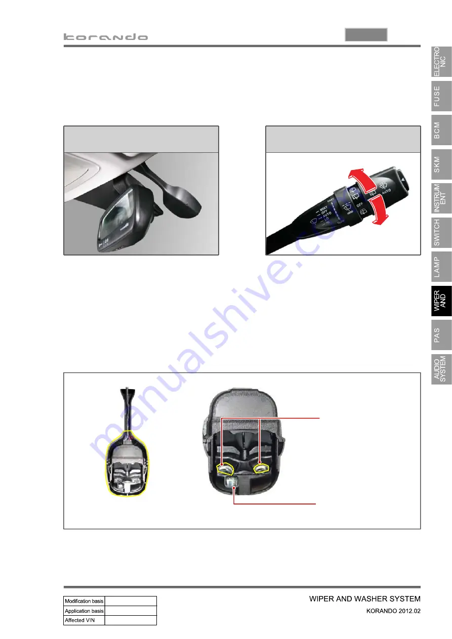
In the rain sensing wiper operation system, the rain sensing unit only sends the information about
the amount of rain drops to the BCM, and it does not operate the wiper directly. The wiper and
washer are controlled by the BCM according to the driver's choice.
Rain sensing unit
Multifunction wiper switch
AUTO and sensitivity control
This sensor emits infrared rays through
LED and then detects the amount of rain
drops by receiving the rays reflected off
the
sensing
section
(rain
sensor
mounting section on the windshield) with
photodiode.
AUTO: Wiper operates automatically by
rain sensor
FAST <-------> SLOW:
Auto delay/auto speed control.
A position that can control the sensitivity
for the amount of rains on the windshield
and transmit the wiping request signal
accordingly.
Rain sensor emitter lens
Auto light sensor sensing
portion
Summary of Contents for Korando 2012
Page 1: ......
Page 2: ......
Page 3: ......
Page 4: ......
Page 5: ......
Page 6: ......
Page 7: ......
Page 8: ......
Page 9: ......
Page 10: ......
Page 11: ......
Page 12: ......
Page 13: ......
Page 14: ......
Page 15: ......
Page 16: ......
Page 17: ......
Page 18: ......
Page 19: ......
Page 20: ......
Page 21: ......
Page 22: ......
Page 23: ......
Page 24: ......
Page 25: ......
Page 26: ......
Page 27: ......
Page 28: ......
Page 29: ......
Page 30: ......
Page 31: ......
Page 32: ......
Page 33: ......
Page 34: ......
Page 35: ......
Page 36: ......
Page 37: ......
Page 38: ......
Page 39: ......
Page 40: ......
Page 41: ......
Page 42: ......
Page 43: ......
Page 44: ......
Page 45: ......
Page 46: ......
Page 47: ......
Page 48: ......
Page 49: ......
Page 50: ......
Page 51: ......
Page 52: ......
Page 53: ......
Page 54: ......
Page 55: ......
Page 56: ......
Page 57: ......
Page 58: ......
Page 59: ......
Page 60: ......
Page 61: ......
Page 62: ......
Page 63: ......
Page 64: ......
Page 65: ......
Page 66: ......
Page 67: ......
Page 68: ......
Page 69: ......
Page 70: ......
Page 71: ......
Page 72: ......
Page 73: ......
Page 74: ......
Page 75: ......
Page 76: ......
Page 77: ......
Page 78: ......
Page 79: ......
Page 80: ......
Page 81: ......
Page 82: ......
Page 83: ......
Page 84: ......
Page 85: ......
Page 86: ......
Page 87: ......
Page 88: ......
Page 89: ......
Page 90: ......
Page 91: ......
Page 92: ......
Page 93: ......
Page 94: ......
Page 95: ......
Page 96: ...MODIFIED ITEMS 1 EXTERIOR 2 INTERIOR 3 CHASSIS 2 4 6 ...
Page 103: ......
Page 104: ...01 3 0000 00 1 LAYOUT Right side view Left side view Rear view Front view ...
Page 114: ...01 13 0000 00 4 CODING AND SETUP 1 Engine Variant Coding ...
Page 131: ......
Page 136: ...02 7 0000 00 ...
Page 137: ...02 8 ...
Page 138: ...02 9 0000 00 ...
Page 139: ...02 10 ...
Page 154: ...02 25 0000 00 Timing gear cover case TGCC TGCC Oil seal Screw plug ...
Page 169: ...03 12 4 Fuel System Check Procedure ...
Page 184: ...03 27 0000 00 3 Input Output devices ...
Page 186: ...03 29 0000 00 4 Flow Diagram of Fuel Supply System ...
Page 187: ...03 30 5 Circuit Diagram ...
Page 193: ...04 8 3 INPUT OUTPUT OF INTAKE SYSTEM ...
Page 194: ...04 9 0000 00 4 OPERATING PROCESS Work Flow ...
Page 197: ...04 12 5 CIRCUIT DIAGRAM ...
Page 198: ...05 3 0000 00 1 TROUBLESHOOTING 1 Work Flow ...
Page 201: ...05 6 3 OPERATING PROCESS 1 Exhaust Gas Flow 2 Input Output Devices ...
Page 209: ...06 10 Defects caused by reasons other than that of the turbocharger 4 ...
Page 211: ...06 12 2 Work Flow for Troubleshooting ...
Page 212: ...06 13 0000 00 ...
Page 213: ...06 14 ...
Page 214: ...06 15 0000 00 ...
Page 215: ...06 16 ...
Page 219: ...06 20 3 INPUT OUTPUT DEVICES ...
Page 226: ...07 7 0000 00 1 Operation Flow 2 OPERATING PROCESS ...
Page 235: ...08 10 3 System Layout ...
Page 236: ...08 11 0000 00 ...
Page 240: ...09 6 3 Checking Battery ...
Page 246: ...09 12 2 CHARGING OPERATION 1 With Smart Key System ...
Page 247: ...09 13 0000 00 2 Without SMART Key System ...
Page 248: ...09 14 3 CIRCUIT DIAGRAM ...
Page 252: ...10 6 2 SYSTEM OPERATION 1 Input Output Diagram of Glow Plug Control Unit 2 System Diagram ...
Page 253: ......
Page 254: ...10 8 3 Circuit Diagram ...
Page 255: ...10 9 1413 00 ...
Page 260: ...10 14 When there is no engine cranking signal after turning the ignition key ON ...
Page 265: ...11 7 1461 00 2 With SMART key system ...
Page 266: ...11 8 3 Without SMART key system ...
Page 267: ......
Page 268: ...11 10 2 Circuit Diagram 1 With SMART key system ...
Page 269: ...11 11 1461 00 ...
Page 270: ...11 12 2 Without SMART key system ...
Page 271: ...11 13 1461 00 ...
Page 286: ...13 6 2 OPERATING PROCESS 1 Schematic Diagram ...
Page 298: ...14 13 1114 00 6 OPERATING TEMPERATURE ...
Page 299: ...14 14 7 ELECTRIC CIRCUIT DIAGRAM ...
Page 304: ...15 6 2 SYSTEM OPERATION 1 Input Output of ECU 1 ECU Block diagram ...
Page 318: ...15 20 b Input Output for variable swirl valve ...
Page 323: ...15 25 0000 00 c Input Output of E EGR system ...
Page 327: ...15 29 0000 00 c Input Output for E VGT system ...
Page 330: ...15 32 c Input Output for oxygen sensor ...
Page 333: ...15 35 0000 00 c Input Output for cooling fan and A C compressor ...
Page 343: ...15 45 0000 00 c Input Output for CDPF control ...
Page 348: ...15 50 3 Input Output for CAN communication ...
Page 391: ...04 9 1740 01 4 INPUT OUTPUT DEVICES ...
Page 392: ...04 10 5 CIRCUIT DIAGRAM ...
Page 397: ......
Page 400: ...03 10 3 SCHEMATIC DIAGRAM OF FUEL FLOWS ...
Page 402: ...05 3 1745 01 1 TROUBLESHOOTING ...
Page 407: ...05 8 PCV valve 2 COMPONENTS Engine ECU WCC Engine CHECK lamp Blow by hose Exhaust manifold ...
Page 409: ...05 10 3 WORK FLOW IN EXHAUST SYSTEM ...
Page 410: ...05 11 1745 01 4 INPUT OUTPUT DEVICES ...
Page 412: ...06 4 2 LAYOUT Ignition Coil Bolt Spark Plug 1 2 3 ...
Page 414: ...06 6 2 COMPONENTS Ignition coil Camshaft position sensor Knock sensor Injector Spark plug ...
Page 416: ...06 8 3 INPUT OUTPUT DEVICES ...
Page 417: ......
Page 418: ...06 10 4 CIRCUIT DIAGRAM ...
Page 419: ...06 11 1443 01 ...
Page 427: ...09 4 2 LAYOUT 1 Alternator Alternator assembly Bolt 1 2 ...
Page 431: ...09 8 2 Battery Inspection ...
Page 436: ...09 13 1452 01 2 CHARGING OPERATION 1 Vehicle without Smart key system ...
Page 437: ...09 14 2 Circuit Diagram ...
Page 439: ...11 4 2 LAYOUT Starter Bolt 1 2 ...
Page 442: ...11 7 1462 01 2 OPERATING PROCESS ...
Page 443: ...11 8 3 CIRCUIT DIAGRAM ...
Page 447: ...15 6 2 SYSTEM OPERATION 1 Input Output of ECU ...
Page 452: ...15 11 0000 00 3 Input Output for Injection Volume Control ...
Page 453: ...15 12 4 Basic Injection Volume Map ...
Page 455: ...15 14 3 Input Output for Ignition System ...
Page 460: ...15 19 0000 00 3 Input Output for Cooling Fan and A C Compressor ...
Page 466: ...15 25 0000 00 3 Input Output for CAN communication ...
Page 468: ......
Page 471: ...01 5 0000 00 VIN NO Engine NO ...
Page 475: ...01 9 0000 00 4 SCHEDULED MAINTENANCE SERVICES ...
Page 476: ...01 10 ...
Page 477: ...01 11 0000 00 ...
Page 478: ......
Page 480: ......
Page 490: ......
Page 492: ......
Page 494: ...02 6 2 COOLANT FLOWS IN COOLING SYSTEM ...
Page 495: ...02 7 0000 00 ...
Page 515: ...14 20 4 CIRCUIT DIAGRAM ...
Page 517: ......
Page 521: ...01 6 Sun visor lamp Glove box lamp Front room lamp 2 INTERIOR LAMP SYSTEM LAYOUT ...
Page 522: ...01 7 0000 00 Center room lamp Luggage lamp Door courtesy lamp ...
Page 525: ...01 10 4 SCHEMATIC DIAGRAM FOR WIRING AND ELECTRICAL DEVICES 1 Wiring Harness Arrangement ...
Page 526: ...01 11 0000 00 2 Electrical Devices Mounting Locations ...
Page 527: ...01 12 3 Connector Ground And Splice Pack Connector ...
Page 528: ...01 13 0000 00 Ground Splice pack ...
Page 531: ......
Page 537: ...02 8 Engine compartment fuse and relay box I ...
Page 538: ...02 9 8410 00 ...
Page 539: ...02 10 Engine compartment fuse and relay box II ...
Page 540: ...02 11 8410 00 ...
Page 541: ...02 12 Engine compartment fuse and relay box IV ...
Page 542: ...02 13 8410 00 ...
Page 543: ...02 14 Engine compartment fuse and relay box V ...
Page 544: ...02 15 8410 00 ...
Page 546: ......
Page 547: ...02 18 Interior fuse and relay box I ...
Page 548: ...02 19 8410 00 ...
Page 549: ...02 20 Interior fuse and relay box II ...
Page 550: ...02 21 8410 00 ...
Page 551: ...02 22 Interior fuse and relay box III ...
Page 552: ...02 23 8410 00 ...
Page 553: ...02 24 Interior fuse and relay box IV ...
Page 554: ...02 25 8410 00 ...
Page 570: ...03 13 8710 01 ...
Page 586: ...03 29 8710 01 ...
Page 638: ...03 96 Select EMS registration menu and enter the password default value 0000 Press Next 3 ...
Page 640: ...03 98 Once the EMS registration is completed press OK to exit the program 6 ...
Page 643: ...03 101 0000 00 Turn the ignition on and press OK button 6 Wait for 15 seconds 5 ...
Page 644: ......
Page 647: ...04 5 8712 03 Slot Rear bumper antenna Front interior antenna Rear interior antenna Smart key ...
Page 652: ...04 10 Passive start operation range Passive START actuation area Vehicle interior ...
Page 666: ...04 24 6 Power Relay Control integrated with ICM 1 OFF to engine starting 2 ACC to IGN ...
Page 667: ...04 25 8712 03 3 IGN to starting 4 IGN engine ON to ACC 5 IGN engine ON to OFF ...
Page 681: ...04 75 8712 03 When the registration is completed click OK button 6 ...
Page 684: ......
Page 690: ...05 8 Engine RPM gauge Speedometer STD LCD ...
Page 691: ...05 9 8010 01 1 SVC 3 Description of Warning Lamps Indicators ...
Page 692: ...05 10 2 STD ...
Page 700: ...05 18 1 SVC 4 OPERATING PROCESS 2 STD ...
Page 701: ......
Page 702: ...05 20 SVC 3 Block Diagram ...
Page 703: ...05 21 8010 01 ...
Page 704: ...05 22 STD ...
Page 705: ...05 23 8010 01 ...
Page 711: ...05 29 8010 01 1 SVC Symbols in SVC 6 System Analysis ...
Page 712: ...05 30 Symbols in SVC via CAN ...
Page 714: ...05 32 2 STD Symbols in STD ...
Page 716: ...05 34 Symbols in STD via CAN ...
Page 717: ...05 35 8010 01 ...
Page 772: ...06 42 Tailgate open switch 7 TAILGATE SWITCH Tailgate open switch ...
Page 784: ...07 12 Sun visor lamp Glove box lamp Front room lamp 1 Layout 2 INTERIOR LAMPS ...
Page 785: ...07 13 8310 00 Center room lamp Luggage lamp Door courtesy lamp ...
Page 794: ......
Page 806: ...08 21 7810 00 System layout 1 Rain sensor coupled wiper operation LIN ...
Page 813: ...08 28 Speed sensitive intermittent wiper interval ...
Page 816: ......
Page 818: ...09 7 8790 00 2 CONFIGURATION Installation of PAS sensor Parking aid unit PAS sensor ...
Page 821: ...09 10 Circuit diagram of ECU Internal circuit diagram of sensors ...
Page 833: ......
Page 838: ......
Page 884: ......
Page 885: ...02 22 3 Hydraulic Circuit Diagram ...
Page 886: ...02 23 3680 01 ...
Page 888: ...02 25 3680 01 3 Drive 2nd 2nd Auto 2 375 1 Power flow 4 Drive 3rd 3rd Auto 1 522 1 Power flow ...
Page 889: ...02 26 5 Drive 4th 4th Auto 1 144 1 Power flow 6 Drive 5th 5th Auto 0 859 1 Power flow ...
Page 890: ...02 27 3680 01 7 Drive 6th 6th Auto 0 676 1 Power flow 8 Reverse 3 178 1 Power flow ...
Page 891: ...02 28 9 Neutral Park Power flow ...
Page 898: ...03 9 3190 01 2 Internal Configuration ...
Page 901: ...03 12 Reverse gear 4th speed gear 5th speed gear 6th speed gear ...
Page 927: ...07 13 3280 17 2 Circuit Diagram ...
Page 928: ...07 14 3 Block Diagram of Input Output ...
Page 932: ...08 5 0000 00 2 TIGHTENING TORQUE Front suspension assembly ...
Page 933: ...08 6 Rear suspension assembly ...
Page 952: ...09 12 4 CIRCUIT DIAGRAM OF STOP LAMP ...
Page 953: ...09 13 4850 00 ...
Page 955: ...10 4 ABS ESP CBS Circuit diagram of wheel speed sensor ...
Page 963: ...10 12 5 SYSTEM OPERATION 1 Block Diagram of ABS HECU ...
Page 974: ...10 23 4890 00 7 CIRCUIT DIAGRAM ...
Page 983: ...11 11 0000 00 5 SYSTEM DESCRIPTION 1 Block Diagram of ESP HECU ...
Page 1007: ...13 4 2 TIGHTENING TORQUE ...
Page 1035: ...01 14 4 A C COOLING CIRCUIT ...
Page 1036: ......
Page 1037: ...01 16 5 CIRCUIT DIAGRAM ...
Page 1038: ...01 17 6810 00 ...
Page 1045: ......
Page 1055: ...02 19 8810 00 5 CIRCUIT DIAGRAM 8810 01 Air bag Curtain air bag Side air bag ...
Page 1061: ...04 4 Sunroof switch 1 SYSTEM LAYOUT Sunroof assembly TILT OPEN Sunroof motor control unit ...
Page 1068: ...04 11 7340 00 5 CIRCUIT DIAGRAM ...
Page 1072: ......
Page 1073: ...07 3 5110 01 Top view Side view Front side Rear view 1 MAJOR DIMENSION ...
Page 1074: ...07 4 2 JACK POINTS 1 2WD ...
Page 1075: ...07 5 5110 01 2 4WD ...
Page 1076: ...07 6 3 SEALING APPLICATION POINTS 1 Dash Panel Engine Tunnel Floor Etc ...
Page 1077: ...07 7 5110 01 2 White Body ...
Page 1078: ...07 8 ...
Page 1079: ...07 9 5110 01 3 Front Rear Door Panel ...
Page 1080: ...07 10 4 Engine Hood Panel ...
Page 1081: ...07 11 5110 01 4 DEADENER APPLICATION POINTS ...
Page 1082: ...07 12 5 UNDER COATING ...
Page 1083: ...07 13 5110 01 6 MAJOR WELDING POINTS 1 Cross Sectional View of Major Panels ...
Page 1084: ...07 14 2 Side Panel ...
Page 1085: ...07 15 5110 01 3 Front Panel ...
Page 1086: ...07 16 4 Apron Panel ...
Page 1087: ...07 17 5110 01 5 Dash Cowl Panels ...
Page 1088: ...07 18 6 Front H Frame Panel ...
Page 1089: ...07 19 5110 01 7 Front Floor Panel ...
Page 1090: ...07 20 8 Rear Floor Panel ...
Page 1091: ...07 21 5110 01 9 Rear End Panel ...
Page 1092: ...07 22 10 Roof Panel ...
Page 1093: ...07 23 5110 01 7 MAJOR BODY DIMENSIONS 1 Under Body Unit mm ...
Page 1094: ...07 24 2 Vehicle Structure Unit mm ...
Page 1095: ...07 25 5110 01 3 Side Structure Unit mm ...
Page 1096: ...07 26 4 Windshield Glass Area Unit mm ...
Page 1097: ...07 27 5110 01 5 Tail Gate Area Unit mm ...
Page 1098: ...07 28 6 Front End Unit mm ...
Page 1099: ...07 29 5110 01 7 Engine Compartment Unit mm ...
Page 1100: ...07 30 8 Back Panel Unit mm ...
Page 1101: ...07 31 5110 01 8 GAP CHART 1 Side Body Unit mm ...
Page 1102: ...07 32 2 Front Unit mm ...
Page 1103: ...07 33 5110 01 3 Rear Unit mm ...
Page 1104: ......


