3
Application
Access tabletop accessory for
indoor call stations for converting
from a wall to a tabletop device.
Slipproof console.
Electrostatic charging
Mounting, installation and servicing
work on electrical devices may only
be performed by a suitably qualified
electrician.
Modern furniture is coated with an
enormous variety of different lacquer
and plastic finishes. Constituents of
these materials can result in sof
tening of the plastic feet in tabletop
devices and so impair the surface of
the furniture. Please appreciate that
the manufacturer is unable to accept
any liability.
Electrical voltage
As a result of electrostatic charging,
direct contact with the circuit board
can result in destruction of the
device. Direct contact with the circuit
board must therefore be avoided.
Scope of delivery
•
AZTV 870... comprising:
•
Slipproof table foot with pre
assembled cable strain relief device
•
Spacer plate for height compensa
tion in devices in individual version,
prefitted when a black table foot
is used
•
2 8pole connecting cables, 3 m
long with RJ45 plug
•
This product information
English
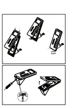
Mounting
1
Open the device from the back
by pressing in the locking lever. The
removed back with adapter circuit
board is no longer required, and can
be disposed of. This is replaced by
the provided table foot.
When using a white table foot and
for devices in individual version,
the spacer plate must be inserted
between the base plate and the
table foot.
2
Remove the base plate using the 4
round press-fit sleeves and the coun
-
tersunk head screws.
3
Place the base plate on the table
foot. In the case of a telephone with
a front and rear panel, the spacer
plate must be inserted between
the table foot and the base plate
in order to compensate for the
distance.
4
Hook the housing into the base
plate from above and close by
exerting a slight pressure.
5
To remove the housing, insert
screwdriver through the hole in
the table foot and press the catch
upwards. The circuit board remains
in the housing superstructure.
Installation
6
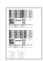
Terminal assignment of the RJ45
socket
a
Left socket LAN assignment
b
Right socket for storey call
button and potential-free contact.
Additionally individual terminals
depending on the mounted
accessories, e.g. AZIO 870-...
Terminal assignment
Link RJ45 socket
1 8
LAN
Right RJ45 socket
3
6
Storey call button
ERT
4
5
Switching contact
30 V, 1 A
1
2
Input via
potentialfree contact
7
8
Switching contact
30 V, 1 A
PIN 3 to PIN 6 are preassigned in
the factory


