background image

10

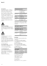
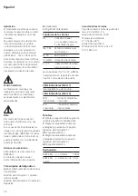
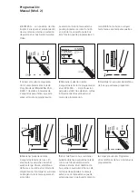
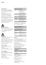
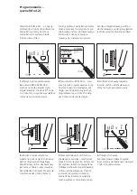
Impiego

Il modulatore video bus nella scatola 
del quadro di distribuzione unisce 
una telecamera analogica al sistema 
In-Home-Bus.
È possibile selezionare tra due 

modalità operative; si può utilizzare 

la telecamera analogica con o senza 
posto esterno. Distanza ammessa 

tra la telecamera e il BVM 650-… 
max. 100 m. Alimentazione tramite 

il sistema In-Home-Bus. È disponi-
bile un contatto di commutazione 
a potenziale zero, ad esempio per 
comandare la telecamera o la luce. 

Tensione elettrica

Gli interventi di installazione, mon-
taggio e assistenza agli apparecchi 
elettrici devono essere eseguiti esclu-
sivamente da elettricisti specializzati.

Avvertenza

• 

La modalità operativa può essere 

modificata esclusivamente in stato 

diseccitato.
• La causa delle interferenze sulle 
immagini possono essere, ad 
esempio, eccessive lunghezze dei 
cavi, diversi circuiti di messa a terra o 
diversi potenziali di terra. In questo 

caso, una soluzione di rimedio può 

essere l’uso di un separatore di 
potenziale video.

Kit di fornitura

• 

Modulatore video bus BVM 650-…

• 

Cavo di collegamento coassiale

• Il presente opuscolo informativo 
sul prodotto

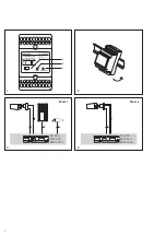
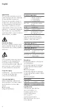
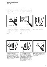
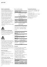
1 Descrizione degli apparecchi
a

 Mod. (selettore della modalità 

operativa)

Posizione interruttore 1 con posto 

esterno

Posizione interruttore 2 senza posto 

esterno

Italiano

b

 Stato (LED)

c

 Prog. Mod. (Pulsante)

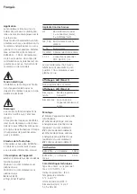
Assegnazione dei morsetti

L/S

Collegamento coassiale
L = Conduttore (bianco),
S = Schermo (nero)

TaK, TbK In-Home-Bus derivazione 

della telecamera

Ta, Tb

In-Home-Bus

Vc, GND

Comando telecamera

S1, S1

Contatto a potenziale zero 
30 V AC/DC, 1 A

Le connessioni (Ta, Tb e Vc, GND) 

sono necessarie solo in posizione 

interruttore 1 con posto esterno.

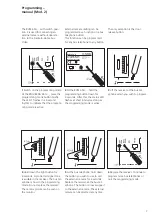
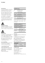
Indicatore LED (Mod. 1)

Non è supportato in questa moda-

lità.

Indicatore LED (Mod. 2)

LED lampeg-
giante

modalità programma

-

zione attiva

LED acceso

Collegamento con 

l’apparecchio interno 
attivo

Montaggio

Montare l’apparecchio sulla guida 

DIN (distribuzione).

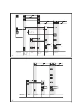
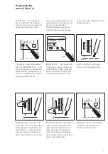
Schema elettrico di principio tele-

camera analogica con posto esterno 

(posizione interruttore 1)

3.1

 Schema di collegamento

Schema elettrico di principio 

telecamera analogica senza posto 

esterno (posizione interruttore 2)

4.1

 Schema di collegamento

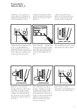
Reichweiten

BVM 650-… <-> Telecamera 100 m

BVM 650-… <-> Posto 

esterno

50 m

Dati tecnici

Tipo di contatto: potenziale zero 

max. 30 V AC/DC, 1 A
Tipo di protezione: IP 20

Temperatura ambiente: 

da 0 °C a +40 °C
Unità di modulare: 3
Dimensioni (mm) Larg. x Alt. x Prof.: 
53,5 x 89 x 60

Summary of Contents for BVM 650-0

Page 1: ...scolo informativo sul prodotto Modulatore video bus Productinformatie Bus Video Modulator Produktinformation Bus video modulator Produktinformation Buss video modulator Información de producto Modulador vídeo para bus Informacja o produkcie Magistralowy modulator wizji Информация о продуктах Шинный видеомоду лятор BVM 650 0 ...

Page 2: ...Bus Video Modulator Bus video modulator Modulateur bus vidéo Prog Mod Mod 1 2 Status IP 20 Bregstraße 1 78120 Furtwangen Germany a b c 1 2 NG 602 BVM 650 BVNG 650 2 2 Tö 6 3 NG 602 BVM 650 BVNG 650 2 4 Mod 2 Mod 1 ...

Page 3: ... Vc Vc b c b Tö Tö Li Li N L1 Tb Tb TbK 230 V AC CE 600 Tö 12 V AC min 20 Ohm Siedle Vario BTLM 650 BTM 650 BVM 650 Mod 1 BTLM BTM IN Gerätebedarf 3 1 230 V AC N L1 BVNG 650 NG 602 TaK TaM TbK TbM TaK L S L S Tö Tö Li Li N L1 TbK 230 V AC CE 600 BVM 650 Mod 2 Gerätebedarf 4 1 ...

Page 4: ...tinformation 1 Gerätebeschreibung a Mod Betriebsartenschalter Schalterstellung 1 mit Türstation Schalterstellung 2 ohne Türstation b Status LED c Prog Mod Taster Klemmenbelegung L S Koaxanschluss L Leiter weiß S Schirm schwarz TaK TbK In Home Bus Kamerazweig Ta Tb In Home Bus Vc GND Kameraansteuerung S1 S1 Potentialfreier Kontakt 30 V AC DC 1 A Die Anschlüsse Ta Tb und Vc GND werden nur in Schalte...

Page 5: ...n einzige Ausnahme ist die Türöffnertaste 1 Programmiermodus einschalten Am BNG BVNG 650 die Taste Prog Mode kurz drücken Die LED 1 blinkt im 2 Sekunden Rhythmus für die Anzeige dass der Programmiermodus aktiv ist 6 Hörer auflegen Weitere Bus Telefone programmieren oder Programmierung beenden 5 Am Bus Telefon die gewünschte Taste für 4 Sekunden gedrückt halten mit welcher die externe Kamera angewä...

Page 6: ...n a Mod operating mode switch Switch position 1 with door station Switch position 2 without door station b Status LED c Prog Mod Button English Terminal assignment L S Coaxial connection L lead white S shield black TaK TbK In Home bus camera branch Ta Tb In Home bus Vc GND Camera actuation S1 S1 Potential free contact 30 V AC DC 1 A The connections Ta Tb and Vc GND are only required in switch posi...

Page 7: ...s the door release button 1 Switch on the programming mode At the BNG BVNG 650 press the programming mode button briefly The LED 1 flashes in a 2 second rhythm to indicate that the program ming mode is active 6 Replace the receiver Continue to program more bus telephones or quit the programming mode 5 At the bus telephone hold down the button you wish to use to call the external camera for 4 secon...

Page 8: ... l appareil a Mod commutateur des modes de fonctionnement Position 1 du commutateur avec platine de rue Position 2 du commutateur sans platine de rue b Statut LED c Prog Mod Touche Français Implantation des bornes L S Raccordement coaxial L conducteur blanc S blindage noir TaK TbK Bus In Home branche caméra Ta Tb Bus In Home Vc GND Commande de la caméra S1 S1 Contact sans potentiel 30 V AC DC 1 A ...

Page 9: ...che gâche 1 Mettre le mode programmation en service Sur le BNG BVNG 650 appuyer brièvement sur la touche mode prog La LED 1 clignote toutes les 2 secondes pour indiquer que le mode programmation est actif 6 Raccrocher le combiné Programmer d autres téléphones bus ou mettre fin à la programmation 5 Sur le téléphone bus appuyer pendant 4 secondes sur la touche souhaitée avec laquelle il s agit de sé...

Page 10: ...ul prodotto 1 Descrizione degli apparecchi a Mod selettore della modalità operativa Posizione interruttore 1 con posto esterno Posizione interruttore 2 senza posto esterno Italiano b Stato LED c Prog Mod Pulsante Assegnazione dei morsetti L S Collegamento coassiale L Conduttore bianco S Schermo nero TaK TbK In Home Bus derivazione della telecamera Ta Tb In Home Bus Vc GND Comando telecamera S1 S1 ...

Page 11: ...ione è il tasto apriporta 1 Attivare la modalità program mazione Sul BNG BVNG 650 premere brevemente il tasto Prog Mode Il LED 1 lampeggia con il ritmo di 2 secondi per indicare che la modalità programmazione è attiva 6 Non agganciare il ricevitore Programmare altri citofoni bus oppure uscire dalla programma zione 5 Sul citofono bus tenere premuto per 4 secondi il tasto con cui si deve selezionare...

Page 12: ...ijving a Mod gebruikstypeschakelaar Schakelaarpositie 1 met deurstation Schakelaarpositie 2 zonder deur station b Status LED c Prog Mod Toets Nederlands Klemmenindeling L S Coax aansluiting L leiding wit S scherm zwart TaK TbK In Home Bus cameratak Ta Tb In Home Bus Vc GND Camera aansturing S1 S1 Potentiaalvrij contact 30 V AC DC 1 A De aansluitingen Ta Tb en Vc GND zijn alleen benodigd in schakel...

Page 13: ...ts worden gepro grammeerd de enige uitzondering is de deuropenertoets 1 Programmeermode inschakelen Op de BNG BVNG 650 de toets Prog Mode kort drukken De LED 1 knippert in een 2 seconden ritme voor de weergave dat de program meermode actief is 6 Hoorn opleggen Verdere Bus Telefoons programmering of het programmering beëindigen 5 Licht toets gedurende 4 seconden ingedrukt houden In de hoorn is een ...

Page 14: ...ontakt Kontaktstilling 1 med dørstation Kontaktstilling 2 uden dørstation b Status LED c Prog Mod Trykknap Dansk Klemmekonfiguration L S Koaksialtilslutning L leder hvid S skærm sort TaK TbK In Home Bus kamera afgrening Ta Tb In Home bus Vc GND Kamerastyring S1 S1 Potentialfri kontakt 30 V AC DC 1 A Tilslutningerne Ta Tb og Vc GND behøves kun i kontaktstilling 1 med dørstation LED indikator Mod 1 ...

Page 15: ...r tast med undtagelse af døråbnertasten 1 Skift til programmeringsfunktion På BNG BVNG 650 trykkes kort på tasten Prog Mode Lysdiode 1 blinker i 2 sekunders rytme for at vise at programmeringsfunktionen er aktiv 6 Læg røret på Programmér yder ligere bustelefoner eller afslut pro grammeringen 5 På bus telefonen holdes den knap som det eksterne kamera ønskes aktiveret med indtrykket i 4 sekunder På ...

Page 16: ...uktinformation 1 Apparatbeskrivning a Läge omkopplare för driftstyp Kopplingsläge 1 med dörrstation Kopplingsläge 2 utan dörrstation b Status LED c Prog Mod Knapp Svenska Klämtilldelning L S Koaxialanslutning L Ledare vit S Skärm svart TaK TbK In Home buss kameragren Ta Tb In Home buss Vc GND Kamerastyrning S1 S1 Potentialfri kontakt 30 V AC DC 1 A Anslutningarna Ta Tb och Vc GND behövs bara i kop...

Page 17: ...rje knapp det enda undantaget är dörr öppningsknappen 1 Koppla på programmeringsmo duset På BNG BVNG 650 tryck kort på knappen Prog Mode LED 1 blinkar med ett intervall på 2 sek under för att indikera att program meringsmoduset är aktivt 6 Lägg på hörluren Programmera ytterligare buss telefoner eller avsluta programmeringen 5 Håll den knapp på buss telefonen intryckt under 4 sekunder med vilken de...

Page 18: ... Mod interruptor de modo de fun cionamiento Posición de interruptor 1 con esta ción de puerta Posición de interruptor 2 sin estación de puerta Español b Estado LED c Prog Mod Interruptor Funciones de los bornes L S Conexión coaxial L Conductor blanco S Pantalla negro TaK TbK Ramal de cámara para bus In Home Ta Tb Bus In Home Vc GND Activación de cámara S1 S1 Contacto libre de poten cial 30 V AC DC...

Page 19: ...nos a la tecla abrepuertas 1 Activar el modo de programa ción Pulsar brevemente la tecla Prog Mode del BNG BVNG 650 El LED 1 destella a intervalos de 2 segundos para indicar que está activo el modo de programación 6 Colgar el auricular Programar otros teléfonos de bus o terminar la programación 5 En el teléfono de bus mantener pulsada durante 4 segundos la tecla con la cual desee seleccionar la cá...

Page 20: ...rzełącznika 1 ze stacją zewnętrzną Pozycja przełącznika 2 bez stacji zewnętrznej b Stan Dioda LED c Prog Mod Przycisk Polski Podłączenie zacisków L S Przyłącze kabla kon centrycznego L przewód biały S ekran czarny TaK TbK Magistrala In Home odgałęzienie kamery Ta Tb In Home Bus Vc GND Sterowanie kamerą S1 S1 Zestyk bezpotencja łowy 30 V AC DC 1 A Złącza Ta Tb i Vc GND są wyma gane wyłącznie w pozy...

Page 21: ...em jest tutaj przycisk otwierania drzwi 1 Włączyć tryb programowania Na aparacie BNG BVNG 650 wcisnąć na krótko klawisz trybu programowania Dioda LED 1 miga co 2 sekundy co sygnalizuje uaktyw nienie trybu programowania 6 Odłożyć słuchawkę Zaprogramować dalsze magistra lowe unifony słuchawkowe lub wyjść z tyrbu programowania 5 Na magistralowym unifonie słu chawkowym wcisnąć i przytrzymać przez 4 se...

Page 22: ...реключателя 1 с дверной панелью вызова Положение переключателя 2 без дверной панели вызова русский b Статус Светодиод c Prog Mod Кнопка Разводка клемм L S Коаксиальное подклю чение L провод белый S экран черный TaK TbK Магистраль камеры In Home Bus Ta Tb Шина In Home Vc GND Активирование камеры S1 S1 Контакт с нулевым потенциалом 30 В 1 A Разъемы Ta Tb и Vc GND требу ются только в положении пере к...

Page 23: ...е исключениe составляет кнопка отпирания двери 1 Включить режим программи рования На BNG BVNG 650 коротко нажать кнопку Режим программирования Светодиод 1 мигает с 2 секундным ритмом сигнализируя о том что режим программирования активен 6 Положить трубку Запрограммировать остальные шинные телефоны или завершить программирование 5 На шинном телефоне удержи вать нажатой 4 секунды любую кнопку с помо...

Page 24: ...Telefon und Telegrafenwerke OHG Postfach 1155 78113 Furtwangen Bregstraße 1 78120 Furtwangen Telefon 49 7723 63 0 Telefax 49 7723 63 300 www siedle de info siedle de 2018 12 18 Printed in Germany Best Nr 210008685 00 ...

Reviews: