4
3 Structure DCIP 650-0
In-Home bus: Video
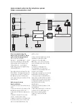
Audio and video communication via IP
DCIP 650-...
In-Home bus link
The DCIP 650-... behaves in the
system in the same way as one
or more bus telephones and is
consequently bound by the same
system limitations (range and
number of users).
The DCIP 650-... comprises the
components:
•
SIVS 610-.., system interface video
server. Processing and adjustment of
data, audio and video.
•
SII 650-... system interface
In-Home. Interface to Siedle
In-Home bus.
•
IPVS 600- .., IP video server.
Processing and adjustment of audio
and video, transmission of data,
audio and video to the IP network.
One DCIP 650-... each is required
per door. A maximum of
29 different call destinations can be
dialled. Dialling is possible by means
of a call button module, code lock
module or display call module.
• Bus programming software
BPS 650-... V2.50 for programming
•
Software Client DCIP SC 600-...
for installation on PC users intended
to receive door calls.
Power supply
The DCIP 650-... is supplied
completely via the video line rectifier
VNG 602-... . Connection takes
place at the SIVS 610-...
An optionally connected
DCA 740-01 is also supplied from
the SIVS 610-... .
The a/b public network interface is
supplied from the TC system. It is
not possible to connect an individual
public network telephone directly to
the a/b line of the DCA 740-01.
Functions
•
Door call from the In-Home bus
and signalling
•
Text display of which door or
which bus telephone is calling.
•
Door release actuation
•
Light actuation
•
Direct dialling and connection to a
door station or a bus telephone.
•
Initiation of switching or control
functions
•
Reception of status messages from
the In-Home bus
Mounting and installation
Connection of the DCIP 650-...
to the In-Home bus takes place at
terminals TaM/TbM at the SII 650-
...
on the monitor branch. Dual
terminals TaM/TbM are provided
for loop through. Connection
can alternatively take place using
a distributor BVVU 650-... . The
devices are intended for switch
panel mounting. These should
preferably be mounted directly one
next to the other.
The maximum conductor length
for device connection between
SIVS 610-... and SII 650-... may be
1 metre. The SII 650-... is linked to
the SIVS 610-... with 6 cores.
Commissioning and
programming
After connection of the supply
voltage, the devices SII 650-... and
SIVS 610-... can be programmed
with the aid of a PRI 602-... USB
(Firmware V2.0 or higher)via the PC.
IPVS 600-0
BVVU 650-...
BVVU 650-...
BVVU 650-...
VNG 602-...
PRI 602-... USB
In-Home-bus: Video
TCP/IP-Network


