4
Application
The flush-mount mounting frame
accessory ZUR 611-... is used to-
gether with the flush-mount housing
end pieces GE 611-0 and the appro-
priate flush-mount housing adaptor,
GZ 611-1, GZ 611-2 or GZ 611-3,
to convert system telephones of line
6.. and of line 7... from wall mount
to flush mount models. These
components are also required when
the telephones are combined with
monitors or when the T 611-... is
also used with multifunctional
module(s) MFM 611-10 as a flush-
mount model.
The following tables indicate which
flush-mount mounting frames with
flush-mount housings and their
dimensions are required for which
combinations.
Installation
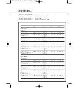
1 Table of flush-mount
combinations
*
= Equipment comb.
**
= Access. flush-mount
frame
***
= Access. flush-mount
housing
****
= Size of cut- out frame for
Hollow-wall fastener
(B X H mm)
*****
= Dimension (B x H x T mm)
Installation with flush-mount
housing
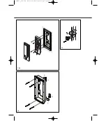
Assemble the required flush-mount
housing configuration, break out the
cable knockout and plaster in the
housing.
Attention
2
Do not remove the injected plaster
protector.
A Installing the system telephone
3
Fasten the proviced end pieces to
the ZUR 611-... using the counter-
sunk head screws.
4
(Not shown)
Remove the injected plaster protec-
tor of the flush-mount housing with
a knife.
5
Use the provided notched dia.
3.5 x 25 mm screws to fasten flush-
mount mounting frame ZUR 611-...
in the flush-mount housing. Snap
the ABS cover strips supplied on the
top and bottom of the flush-mount
mounting frame as shown.
6
Remove the upper half of the
housing of system telephone.
7
Pull the connecting leads through
the cable knockout in the lower half
of the housing and use the supplied
notched screws dia. 3.9 x 10 mm to
fasten to the lower half of the
housing in the flush-mount mount-
ing frame ZUR 611-....
8
(Not shown)
Connect the system telephone as
per corresponding wiring diagram.
9
(Not shown)
Put the upper half of the housing
back in place.
B Installing, for example, the
HT/T MO combination
Carry out steps 1 to 5 as described
above.
10
Open system telephone and
monitor as shown.
11
Break out the knockout links "a"
in the system telephone and lower
half of the monitor. Use the 2 con-
necting elements accompanying the
monitor to screw down the lower
halves.
12
Pull the connecting leads through
the cable opening in the lower
halves of the housing and fasten the
lower halves of the housing in flush-
mount mounting frame ZUR 611-...
with the provided notched screws
dia. 3.9 x 10 mm.
13
(Not shown)
Connect the equip-ment as per
corresponding wiring diagram. Use
the 7-pole cable accompanying the
monitor for the connections
between HT/T 611-..., HTA/HTS/
HTC 711-... / BTS/BTC 750-... and
MOM/ MOC/MOCT 711-...
14
(Not shown)
Put the upper half of the housing
back in place.
Follow the procedure above for
combinations with other equipment
configurations.
Multi-functional modules
MFM 611-10 are always mounted in
a row to the right of the system
telephone T 611-... first; the monitor
follows.
No more than 3 MFM 611-10
modules are to be mounted in a row
with system telephone T 611-...
C Installation with hollow-wall
fastener accessory
A hollow-wall fastener accessory
ZHB 611-0 consists of 2 pairs of
retaining clips and screws.
15
Install an appropriate number of
retaining clips in the flush- mounting
frame accessory as shown, according
to the size of the flush-mount
housing.
a
Fit the supports on to the reverse
side
b
Push the screw through the
appropriate hole in the mounting
frame and at the same time screw in
the retaining clip and the support
16
Fasten the proviced end pieces to
the ZUR 611-... using the counter-
sunk head screws
17
(Not shown)
Install the flush-mount mounting
frame accessory in the hollow wall.
18
(Not shown)
Snap the supplied ABS cover strips
on top and bottom of the flush-
mount moun-ting frame.
19
(Not shown)
Install system telephones or com-
binations as described under A 6 to
9 or B 10 to 14, respectively.
English
Installation
ZUR611_212720 22.05.2002 13:16 Uhr Seite 4


